

-
Leon Zhang sales consultant
-
Email: zxl635973785@gmail.com
-
Phone/WhatsApp: +86 13655813266
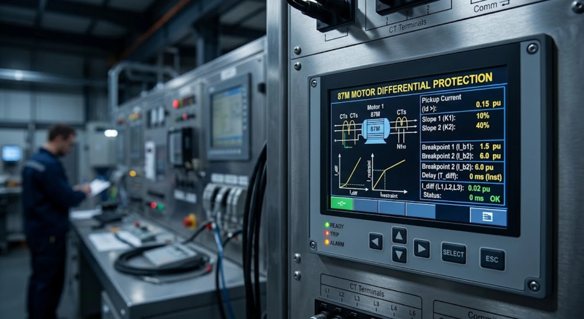
87M Motor Differential Protection Settings: Pickup, Bias and CT Parameters
87M protection settings are configured in the motor protection relay and serve as the core of reliable motor differential protection commissioning and operation. Unlike general overcurrent protection, motor differential protection relies on precise parameter setting in the relay to distinguish internal winding faults from external system disturbances. For power plant, industrial, and EPC field engineers, accurate 87M settings directly determine protection sensitivity, operational stability, and motor equipment safety.
A complete 87M relay configuration requires defining a set of key parameters: differential pickup threshold, bias/restraint characteristics, CT ratio and accuracy parameters, rated motor current matching, high-set differential trip value, and protection operating delay.
This article focuses on practical engineering application, elaborating how to calculate, configure, and verify standard 87M protection settings for on-site commissioning, avoiding generic theoretical descriptions and focusing on actionable field guidelines.
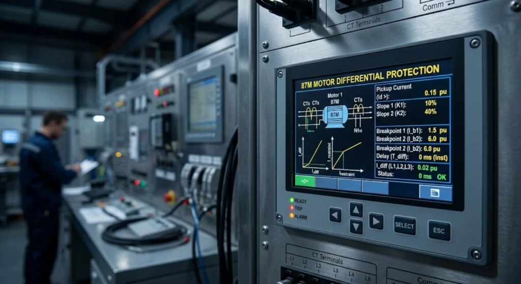
What Are 87M Protection Settings?
87M motor differential protection settings refer to a series of configurable relay parameters that govern fault judgment, current calculation, and trip logic for motor winding differential protection. All motor differential relay settings are designed to balance two core engineering goals: capturing minor internal motor faults sensitively and avoiding maloperation during external faults and normal load fluctuations.
The following table summarizes the core setting items and their practical engineering purposes, covering all mandatory configuration items for standard 87M relay commissioning:
| Setting Parameter | Engineering Purpose |
|---|---|
| Differential Pickup | Sets the minimum differential current threshold for relay operation to detect internal motor winding short-circuit faults |
| Bias / Restraint Characteristic | Suppresses false differential current caused by CT saturation and mismatch during high through-current external faults, ensuring protection stability |
| CT Ratio | Matches relay secondary current measurement with on-site actual CT transformation parameters to ensure accurate current sampling |
| CT Class / Accuracy | Defines CT error limits and saturation performance, providing basic data for pickup and bias setting calculation |
| High-Set Differential | Provides instantaneous trip output for severe internal motor faults to minimize equipment damage and fault expansion |
| Trip Time / Operating Delay | Realizes protection coordination with upstream and downstream devices and avoids maloperation from transient current fluctuations |
| Phase Assignment | Ensures one-to-one correspondence of inlet and outlet current phases for correct differential current comparison |
How Does 87M Differential Protection Determine a Fault?
Before configuring 87M settings, it is necessary to clarify the core fault judgment logic of differential protection. All parameter settings are based on the mathematical relationship between operating differential current and restraint bias current.
Operating Current and Differential Current
The core judgment basis of 87M protection is differential current (Idiff), which is the vector difference between the current entering and leaving the motor protection zone. The basic calculation formula is universally applicable to all motor differential protection schemes:
Idiff=∣I1−I2∣
Where:
- I1= Phase current entering the motor protection zone (CT primary inlet current)
- I2 = Phase current leaving the motor protection zone (CT primary outlet current)
In actual operation, the differential current presents distinct characteristics under different working conditions: balanced current and near-zero Idiff for healthy motor operation, slightly increased spill current caused by CT errors for external faults, and sharply rising Idiff exceeding the protection threshold for internal winding faults.
Operating Current vs Restraint Current
To solve the problem of CT saturation-induced false differential current under high through-current conditions, 87M relays adopt a bias restraint mechanism. Two core current values determine protection action:
- Differential/Operating Current: The unbalanced current generated inside the protection zone, which is the action trigger signal
- Bias/Restraint Current: The reference current dynamically calculated based on through-current, which improves the protection threshold proportionally with fault current
The restraint current calculation formula varies by relay manufacturer:
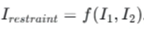
No universal fixed formula applies to all devices, so field settings must strictly follow the specific relay’s technical manual to avoid calculation errors.
How to Set the 87M Differential Pickup
Differential pickup setting is the most critical parameter of 87M protection, directly determining the differential current setting sensitivity and anti-interference capability of the system.
What Is the Differential Pickup Setting?
The differential pickup value is the minimum operating differential current threshold calibrated in the 87M relay. When the real-time calculated Idiff exceeds this value and meets the bias restraint characteristic requirements, the relay will initiate a trip or alarm command. This parameter is the core index to identify minor internal motor faults.
Factors That Affect the Pickup Setting
Field pickup values cannot be set arbitrarily. All influencing factors that cause unbalanced current in normal operation and external faults must be fully considered:
- CT inherent accuracy error and parameter mismatch
- CT saturation characteristics under high fault current
- Relay internal measurement and sampling error
- Normal three-phase load imbalance of the motor
- Transient current impact during motor starting
- On-site cable wiring deviation and contact resistance error
- Expected sensitivity requirements for minor winding turn-to-turn faults
How to Calculate the Initial Differential Current Setting
There is no fixed universal percentage pickup value for all 87M protection scenarios. The standard engineering calculation principle is:
Minimum Differential Pickup Setting > Maximum Expected Spill Current + Engineering Safety Margin
The maximum spill current refers to the maximum unbalanced current generated by CT errors, measurement deviation, and load imbalance under normal operation and external fault conditions. The final setting must be comprehensively corrected based on the relay manufacturer’s characteristic curve, actual CT performance parameters, motor rated current, and project protection design philosophy.
Example of Differential Pickup Calculation
The following calculation is for engineering illustration only, not a universal standard setting. Actual project parameters shall prevail:
Basic Field Parameters:
- Motor rated current: 250 A
- CT ratio: 300/5 A
- Maximum CT mismatch error: 3%
- Relay measurement error: 2%
- Engineering safety margin: 5%
Calculation Process:
Maximum comprehensive spill current error = 3% + 2% = 5% of rated secondary current
Minimum pickup threshold = 5% + 5% margin = 10% of CT secondary rated current
Final selected differential pickup setting: 0.5 A (10% × 5 A secondary rated current)
Note: Example values are for illustration only. All field settings must be verified against actual device and equipment parameters.
87M Bias and Restraint Settings
Bias/restraint setting is the key to solving the contradiction between 87M protection sensitivity and stability, which effectively avoids maloperation caused by CT saturation during external faults.
What Is Bias in Motor Differential Protection?
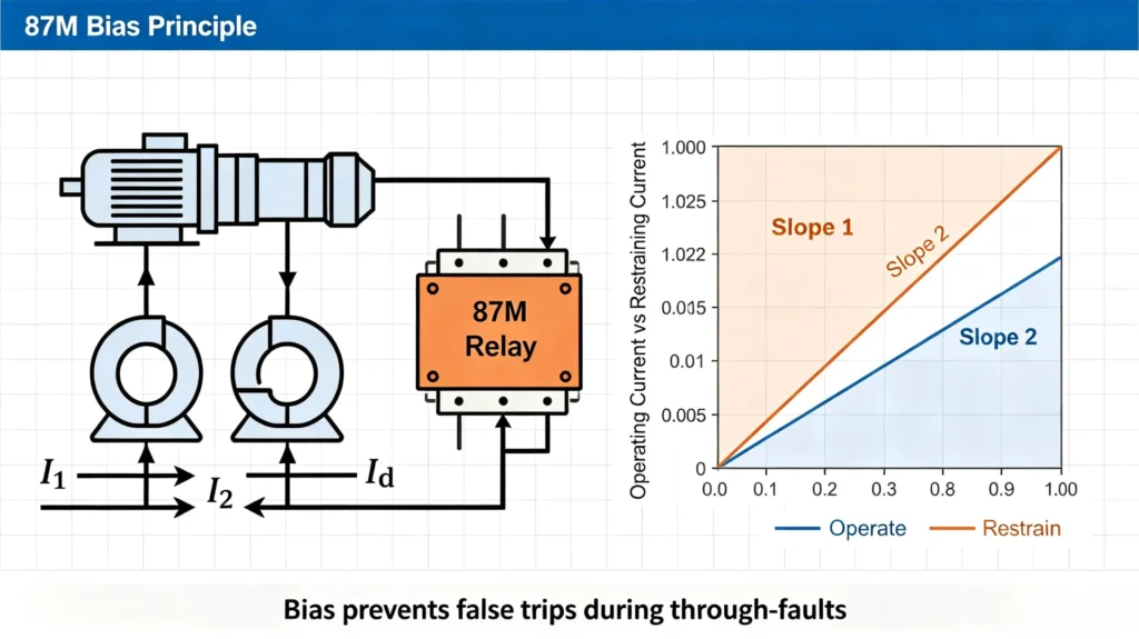
Bias (restraint) is a dynamic threshold adjustment mechanism for 87M relays. Its core function is to improve the differential protection operating threshold proportionally with the increase of system through-fault current. When high through-current causes CT saturation and unbalanced spill current, the bias characteristic suppresses false trip signals to ensure protection stability for external faults.
Why Is Bias Needed for 87M Protection?
The core value of bias setting is to distinguish internal and external fault scenarios accurately:
- Internal Motor Fault: The current difference inside the protection zone increases significantly, the actual differential current exceeds the bias-adjusted threshold, and the relay operates correctly to trip
- External System Fault: The through-current increases sharply, CT saturation generates unbalanced spill current, and the rising bias threshold offsets the false differential current to prevent maloperation
Single-Slope vs Dual-Slope Differential Characteristics
Most industrial 87M relays support two bias characteristic modes to adapt to different current operating conditions:
- Single-Slope Characteristic: Applies to conventional low-power motors. The bias ratio is fixed in the full current range, with simple configuration and stable performance
- Dual-Slope Characteristic: Adapts to medium and large critical motors. It sets a low slope for low-current regions to ensure minor fault sensitivity and a high slope for high-current regions to resist CT saturation interference, with a set transition current point for slope switching
How to Select the 87M Bias Setting
Factors Used to Select Bias
The bias ratio is not fixed and needs to be matched with on-site power system and equipment parameters:
- Maximum through-fault current of the motor branch
- CT saturation limit curve and accuracy class
- CT secondary burden resistance and lead wire resistance
- Maximum allowable CT mismatch error
- Built-in algorithm characteristics of the 87M relay
Higher Bias vs Lower Bias
The bias setting is a balance between protection sensitivity and stability, with distinct advantages and risks for high and low values:
| Bias Setting | Advantage | Potential Risk |
|---|---|---|
| Lower Bias | Higher sensitivity to minor internal winding faults | Small stability margin, prone to maloperation under severe CT saturation |
| Higher Bias | Excellent stability for external faults and strong anti-interference ability | Reduced sensitivity, possible missed detection of minor turn-to-turn faults |
Core Principle: The correct 87M bias setting must balance internal fault sensitivity and external fault stability according to actual working conditions.
CT Parameters Required for 87M Relay Settings
CT parameters are the basic data support for all 87M protection settings. Inconsistent CT configuration is the primary cause of differential protection maloperation and failure to operate. This section complements the supporting content of the previous Motor Differential Protection CT Wiring article, focusing on setting-related parameter calibration.
CT Ratio
Common industrial motor CT ratios include 100/5 A, 200/5 A, 400/5 A, etc. The CT ratio configured in the 87M relay must be completely consistent with the on-site actual transformation ratio. Mismatched ratio parameters will lead to wrong secondary current conversion and continuous false differential current.
CT Class and Accuracy
Protection-grade CTs (commonly 5P20, 10P20) are mandatory for 87M differential protection. The CT accuracy class defines the maximum error under rated saturation multiple, directly determining the allowable spill current range and the lower limit of pickup and bias settings. Measurement-grade CTs cannot be used for differential protection due to poor saturation resistance.
CT Secondary Current
Field CTs are divided into 1 A and 5 A secondary output specifications. The 87M relay’s current input module and internal configuration must match the CT secondary specification. Mixed configuration of 1 A/5 A parameters will cause full-scale current measurement deviation.
CT Burden and Lead Resistance
CT saturation performance is closely related to secondary burden. Excess lead wire resistance, terminal block contact resistance, and secondary loop load will increase CT error under high fault current. Burden parameters must be measured on-site and included in the bias setting calculation basis.
CT Polarity
Incorrect CT polarity is a common on-site fault that causes persistent differential current in normal motor operation. Polarity verification does not require repeated wiring analysis here; refer to the professional guide: Motor Differential Protection CT Wiring: 6-CT and Self-Balancing Schemes for standard polarity calibration methods.
CT Parameters and Differential Current Calculation
Accurate current conversion and differential value calculation are the basis for verifying 87M setting rationality.
Converting Primary Current to CT Secondary Current
Standard primary-secondary current conversion formula for CT:

Matching CT Parameters With the Relay
The full-link matching logic of 87M protection is: actual motor operating primary current → on-site CT ratio conversion → standard secondary current output → relay sampling and calculation → comparison with preset pickup and bias thresholds → fault judgment and trip output.
Calculating Differential Current From CT Inputs
Simple numerical example for field verification:
If relay sampled CT inlet secondary current = 2.45 A, outlet secondary current = 2.42 A
Idiff=∣2.45−2.42∣=0.03A
The relay compares the calculated Idiff with the set pickup threshold and dynamic bias threshold. If the value is lower than the threshold, the protection remains stable; if it exceeds the threshold and meets the characteristic curve requirements, a trip action is triggered.
Recommended 87M Settings for Different Motor Applications
87M settings cannot be standardized. Different motor operating scenarios have differentiated sensitivity and stability requirements, so targeted setting optimization is required.
Medium-Voltage Industrial Motors
Focus on matching rated current and conventional fault characteristics: set moderate pickup and bias values, ensure stable operation during motor starting and external short-circuit faults, and reliably detect conventional winding internal faults. Prioritize coordination with upstream overcurrent protection.
Large Critical Motors
Applicable to power plant main motors, production core equipment: appropriately reduce pickup values to improve minor fault sensitivity, adopt dual-slope bias characteristics, match high-performance 5P-class CTs, and configure redundant protection logic to realize fast fault clearing and avoid equipment major damage.
Motors With High Starting Current
87M differential protection starting restraint logic is different from conventional overcurrent protection. For motors with 6-8 times rated starting current, focus on checking CT transient saturation during starting, appropriately increase the low-current bias margin, avoid maloperation caused by transient unbalanced current, and ensure no protection misjudgment during the full starting cycle.
87M Protection Settings Example
The following complete case is for engineering reference only. Actual settings must be adjusted according to project-specific parameters and relay manuals.
Motor and CT Basic Data
| Parameter | Example Value |
|---|---|
| Motor Rated Voltage | 6.6 kV |
| Motor Rated Current | 280 A |
| CT Ratio | 300/5 A |
| CT Secondary Rating | 5 A |
| CT Class | 5P20 |
| Maximum Branch Fault Current | 20 kA |
Final 87M Setting Table
| Setting Parameter | Selected Value | Setting Basis |
|---|---|---|
| Differential Pickup | 0.5 A | CT comprehensive error + engineering safety margin |
| Slope 1 (Low Current) | 10% | Ensure minor fault detection sensitivity |
| Slope 2 (High Current) | 25% | Resist high-current CT saturation interference |
| High-Set Differential | 5 A | Instant trip for severe short-circuit faults |
| Trip Delay | 0 s | Fast clearing of internal faults |
Disclaimer: Actual settings must be calculated and verified against the specific relay manufacturer’s application manual and the motor protection study report of the project.
87M Settings for Internal and External Faults
Normal Motor Operation
Three-phase current is balanced, CT sampling error is within the allowable range, differential current is close to zero, and the 87M relay remains stable without alarm or trip.
External Fault
System through-current increases sharply, local CT saturation generates small unbalanced spill current. The dynamic bias threshold rises synchronously to offset the false differential current, and the protection maintains stable operation to avoid maloperation.
Internal Motor Fault
Winding short-circuit causes current imbalance inside the protection zone, differential current rises rapidly, exceeds the pickup threshold and bias characteristic limit, and the 87M relay outputs a trip command to cut off the fault current quickly.
Common Mistakes When Setting a Motor Differential Relay
Most on-site 87M protection failures are caused by non-standard setting and commissioning, and the following typical mistakes should be avoided:
- Overly Low Pickup Setting: Excessively sensitive threshold amplifies CT mismatch and measurement error, leading to frequent nuisance tripping during normal operation and motor starting
- Overly High Pickup Setting: Excessively conservative threshold reduces protection sensitivity, resulting in failure to detect minor turn-to-turn faults and latent equipment hazards
- Ignoring CT Saturation Characteristics: Fixed bias setting without considering high-current saturation leads to external fault maloperation
- Mismatched CT Ratio Configuration: Inconsistent relay parameters and on-site CT actual parameters cause long-term false differential current
- Neglecting CT Polarity Verification: Wrong polarity leads to current superposition error, triggering abnormal protection action
- Blind Copy of Existing Settings: Motor rated current, CT parameters, and system fault level vary in different projects. Copied settings cannot adapt to on-site conditions
How to Test and Verify 87M Protection Settings
Setting confirmation must be completed through on-site commissioning tests to ensure 100% matching between parameters and actual protection performance.
Verify CT Parameters
Confirm CT ratio, secondary rating, accuracy class, on-site polarity, and wiring integrity one by one to eliminate basic parameter errors.
Secondary Injection Test
Inject standard analog current into the relay secondary loop, verify phase current sampling accuracy, differential current calculation value, pickup threshold action accuracy, and bias characteristic curve compliance.
Differential Protection Stability Test
Simulate external high through-current faults, check whether the relay maintains stable operation, and verify the effectiveness of bias anti-interference capability.
Differential Protection Trip Test
Simulate internal motor winding faults, confirm pickup threshold action, trip output signal, breaker linkage action, and event recording integrity.
87M Protection Settings Checklist
Universal on-site commissioning checklist for standardized setting verification:
CT Data Verification
- CT ratio configuration consistent with site actuals
- CT secondary current specification (1A/5A) matched
- CT accuracy class meets protection requirements
- CT polarity fully verified and correct
- CT secondary burden and lead resistance qualified
Relay Setting Verification
- Differential pickup value calculated and set correctly
- Bias/slope parameters matched with fault level
- High-set differential threshold configured reasonably
- Trip delay and phase assignment accurate
Commissioning Test Verification
- CT polarity test passed
- Secondary injection calibration completed
- External fault stability test qualified
- Internal fault pickup and trip test qualified
Frequently Asked Questions About 87M Settings
What are the main 87M protection settings?
Core 87M protection settings include differential pickup threshold, bias/restraint slope characteristics, high-set differential value, trip delay, CT matching parameters, and phase assignment configuration, which jointly determine the protection’s fault judgment logic and operating performance.
How is the differential current setting calculated?
The differential current setting is based on the maximum unbalanced spill current caused by CT error, measurement deviation, and load imbalance, plus a reserved engineering safety margin. The final value is corrected according to CT performance and relay characteristics, with no fixed universal standard.
What is bias in motor differential protection?
Bias is a dynamic restraint mechanism for 87M relays. It increases the protection operating threshold proportionally with the rise of system through-current, effectively suppressing false differential current caused by CT saturation and mismatch during external faults to prevent maloperation.
How do you select the pickup setting for a motor differential relay?
Pickup setting selection comprehensively considers CT accuracy, saturation performance, relay measurement error, motor load imbalance, starting transient current, and fault sensitivity requirements, following the principle of “higher than maximum spill current plus safety margin”.
What CT parameters are required for 87M protection?
Mandatory CT parameters include transformation ratio, secondary current specification, accuracy class, saturation performance, secondary burden resistance, and polarity, all of which are the basic basis for 87M setting calculation and normal operation.
Why is CT saturation important for 87M settings?
CT saturation will generate a large number of unbalanced false currents under high through-current external faults. Without matched bias settings, the false differential current will trigger protection maloperation, seriously affecting motor system operation stability.
Can the same 87M settings be used for different motors?
No. 87M settings are highly customized. Different motors have different rated currents, matching CT parameters, system fault levels, and operating conditions. Blindly copying settings will lead to insufficient sensitivity or poor stability, which cannot meet project protection requirements.
87M Motor Differential Protection Relay
Reliable 87M motor differential protection performance depends on professional relay hardware and algorithm support. A qualified 87M relay should support flexible CT parameter configuration, single/dual-slope bias characteristic switching, accurate differential current calculation, and complete commissioning and test functions.
Our professional 87M motor differential protection relay is fully adapted to medium and large industrial motor application scenarios, matching standard setting calculation logic and commissioning specifications described in this article, providing stable, sensitive, and reliable winding fault protection for industrial and power plant motor equipment. For product parameters and solution details, refer to: Motor Differential Protection – 87M.
Technical Reference Documents & Data Sources
- IEC 60282-1:2020 High-voltage fuses and motor protection standard specifications
- IEC 61850:2018 Substation automation and relay protection configuration guidelines
- IEEE C37.113:2019 Motor differential protection application and setting standard
- GB/T 14817-2017 Instrument transformer technical specification for protection
- Manufacturer official application manuals for mainstream 87M differential relays
- Industrial motor protection system engineering commissioning industry guidelines



About Author

Hello, I'm Leno Zhang. I have 15 years of experience in the power relay protection industry with extensive pre-sales and after-sales project experience. Our company specializes in various complete sets of relay protection and automation equipment. I can assist customers in solving all practical on-site project challenges and provide optimal integrated solutions.
Tell Us Your Requirement
High Quality
Stable performance, reliable design, ensuring safe operation for power system protection and grid stability.
Fast Delivery
Timely delivery to support your urgent orders and project schedules efficiently and professionally at any time.
Best Warranty
Professional Warranty: Reliable after-sales support for stable relay protection and long-term customer satisfaction.