
-
Leon Zhang Sales Manager
-
Email: sale@relayprotect.com
-
Phone/WhatsApp: +86 13655813266

Control Relay: Coil Voltage, Contact Forms and Ratings
What is a control relay and how does it differ from a protective relay?
A control relay, named in IEC 60050 (IEV 447-01-15), turns an external command into a control signal, switching pilot devices, interlocks and contactor coils rather than measuring fault current. IEC 60947-5-1:2024 sets the AC-15 and DC-13 contact ratings that decide whether the output survives an inductive coil, and IEC 61810-1:2015 covers the electromechanical element. It does three jobs: isolation, keeping a 24 V DC logic circuit apart from a 120 V or 230 V AC control circuit; amplification, where a 0.5 A output drives a coil switching a 6 A inductive load; and multiplication, carrying one command to several rungs. Common coil voltages are 24 V DC, 48 V DC, 120 V AC and 230 V AC; an electromechanical coil picks up near 75-80% of nominal and drops out between 10% and 20%. A protective relay under IEC 60255-1:2022 does a different job. North American drawings use device numbers from ANSI/IEEE C37.2-2022. Setting review and quotation within 12 hours, MOQ 1, 7-15 working days.
Control relay is the IEC 60050 (IEV 447-01-15) name for a relay that turns an external command into a control signal, switching pilot devices, interlocks and contactor coils rather than measuring fault current. IEC 60947-5-1:2024 sets the AC-15 and DC-13 contact ratings that decide whether the output survives an inductive coil; IEC 61810-1:2015 covers the electromechanical element itself. A protective relay under IEC 60255-1:2022 does a different job.
Written by RelayProtect Editorial, protection engineering desk. Technical review by RelayProtect Controls Engineering Group. Last reviewed 2026-11.
The definition in the International Electrotechnical Vocabulary is deliberately broad. A simple unit translates one command into one signal, such as a close order to a breaker. A more elaborate unit issues a sequence, for example opening a disconnector, closing a bus tie and reclosing a second disconnector to move a circuit between busbar sections.
A third kind supervises a quantity such as voltage or frequency and produces a signal derived from it, as an under-frequency load-shedding device does. All three sit on the control side of the panel. None of them measures current with a protection-class accuracy, and none of them carries motor branch current. North American drawings label these functions with device numbers from ANSI/IEEE C37.2:2022, while IEC schematics use letter symbols and rung numbers.
At a Glance
- IEC 60050 IEV 447-01-15 defines the term by its function: turning a command into a control signal.
- AC-15 and DC-13 ratings under IEC 60947-5-1:2024 govern switching of contactor and solenoid coils.
- A 24 V DC coil marking says nothing about the voltage its contacts may switch.
- Control relays usually switch pilot duty below 10 A, not motor branch current.
- Interposing units isolate a PLC transistor output from a 120 V AC coil circuit.
- A seal-in rung holds a start command through one normally open auxiliary contact.
- IEC 61810-1:2015 covers electromechanical elementary relay endurance and dielectric tests.
- A protective relay measures CT and VT inputs; control relays do not measure.
What a Control Relay Does in a Control Circuit
The job starts with an input that carries little power: a PLC transistor output, a pushbutton, a selector switch, a limit switch, a thermostat or a permissive from another panel. The output side switches pilot lamps, contactor coils, small solenoid valves, alarm buzzers, PLC inputs and interlock chains. Three functions repeat across almost every application.
The first is isolation, which keeps a 24 V DC logic circuit galvanically separate from a 120 V AC or 230 V AC control circuit. The second is amplification, where a 0.5 A semiconductor output drives a relay coil that in turn switches a 6 A inductive load. The third is multiplication, where four isolated contact pairs carry the same command to four different rungs. A panel drawing that shows only a coil voltage hides all three.
Name the job first.
Selecting a relay for a live project?
Send the system voltage, CT ratio and tripping scheme. Our engineers confirm the model and reply within 12 hours.
| Device | What it senses | What it switches | Governing standard |
|---|---|---|---|
| Auxiliary or interposing relay | A command or a control voltage | Pilot lamps, contactor coils, PLC inputs | IEC 60947-5-1:2024 |
| Time relay | Elapsed time after an input | Sequenced start or stop contacts | IEC 61812-1:2011 |
| Latching relay | A set or reset pulse | Maintained state with no coil power | IEC 61810-1:2015 |
| Protective relay | CT and VT inputs, threshold logic | Trip, alarm, lockout, reclosing | IEC 60255-1:2022 |
| Contactor | A coil command | Motor and heater power circuits | IEC 60947-4-1:2023 |
Table 1. Five devices that appear on the same panel schedule, separated by what each one senses and what each one switches.
Control Relay vs Protective Relay, Power Relay and Contactor
Four names describe four duties, and a catalogue current rating does not separate them. A relay used for logic typically switches pilot duty below 10 A. A power relay switches larger loads, often 3 A to 30 A, with contact material and arc handling sized for the current. A contactor repeats motor starting and breaking under the AC-3 utilisation category of IEC 60947-4-1:2023.
A protective relay measures electrical quantities and issues a trip under IEC 60255-1:2022. The dividing line is the declared switching duty, not the physical size of the box and not a universal ampere threshold. A resistive 10 A rating says nothing about breaking a 400 V AC contactor coil with a six-times inrush.
| Device | Primary duty | Rating that matters | Standard |
|---|---|---|---|
| Auxiliary relay | Logic, interlock, pilot switching | AC-15 or DC-13 at the actual voltage | IEC 60947-5-1:2024 |
| Power relay | Higher-current load switching | Load current, inrush, arc suppression | IEC 61810-1:2015 |
| Contactor | Repeated motor or heater switching | AC-3 operational current and duty | IEC 60947-4-1:2023 |
| Protective relay | Fault detection and trip decision | Accuracy, speed, coordination | IEC 60255-1:2022 |
| PLC output | Logic and sequencing | Output current and voltage type | IEC 61131-3:2025 |
Table 2. Duty boundaries between switching, logic and protection devices found on one motor control schematic.
Read the declared duty.
Coil Voltage, Pickup and Dropout
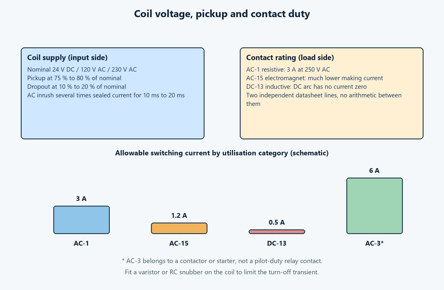
A coil is specified by its supply, not by its contacts. Common control voltages are 24 V DC, 48 V DC, 120 V AC and 230 V AC at 50 Hz or 60 Hz. An electromechanical coil picks up at roughly 75 % to 80 % of nominal voltage and drops out somewhere between 10 % and 20 %, so a feeder that sags to 70 % during a motor start can chatter the armature and pit the contacts.
AC coils draw an inrush several times their sealed current for the first 10 ms to 20 ms, which is why a shared 24 V DC supply with a weak reserve browns out a whole DIN rail at once. DC coils avoid that inrush but need a suppression path when they switch off.
Check both numbers.
Suppression belongs on the coil, not as an afterthought. A diode across a DC coil limits the turn-off transient but slows the dropout by 5 ms to 15 ms, which matters in a fast interlock. A varistor or an RC snubber works on AC coils and leaves the release time closer to the unsuppressed value.
IEC 61000-4-4:2012 describes the fast transient burst that these coils inject into a shared feeder, and IEC 61000-4-5:2014 covers the larger surge. A suppression component that is missing shows up as a random PLC input flicker, not as a relay failure, and gets diagnosed as a software fault for weeks.
Control Relay Contact Ratings: AC-15 and DC-13
Contact figures published without a utilisation category are almost always AC-1 resistive values. A 3 A at 250 V AC line looks generous until the load is a solenoid or a contactor coil. IEC 60947-5-1:2024 assigns those electromagnet loads to AC-15 for alternating current and DC-13 for direct current, with allowable currents far below the resistive figure.
Pull-in current on a 230 V AC coil reaches six times the sealed value for 10 ms to 20 ms; break energy on a DC coil is harder still because a direct-current arc has no natural zero crossing. A contact that survives 100 000 resistive operations may weld after a few thousand coil breaks.
Ask the supplier for the electrical life curve at the actual load category, not the 10 million operation mechanical life. Contact material matters too: silver alloy handles general duty, while silver tin oxide resists the arc that follows an inductive break. A protective device such as a varistor across the load reduces that arc energy and extends the interval between replacements. Where the load is a motor branch circuit, stop and specify a contactor instead.
| Utilisation category | Typical load | Stress on the contact | What to verify |
|---|---|---|---|
| AC-1 | Resistive heaters, lamps | Low, no significant inrush | Steady current and voltage |
| AC-15 | AC electromagnet coil, contactor coil | Six-times pull-in current for 10 ms to 20 ms | Making current at 230 V AC |
| DC-13 | DC solenoid, DC contactor coil | Inductive arc with no current zero | Breaking current at 24 V DC or 110 V DC |
| AC-3 | Motor starting and running | Locked-rotor current and repeated breaks | Contactor rating, not a relay rating |
| AC-15 plus suppression | Coil with varistor or RC snubber | Reduced turn-off transient | Life curve with the suppressor fitted |
Table 3. Utilisation categories from IEC 60947-5-1:2024 and the coil stress each one is written for.
Rate the breaking duty.
Contact Forms, Poles and the Seal-In Rung
Contact logic is described in the de-energised state. A normally open contact, Form A, closes when the coil picks up. A normally closed contact, Form B, opens. A changeover contact, Form C, transfers one common terminal between the two. Plug-in industrial units commonly offer SPDT, DPDT or four-pole arrangements, so one coil can drive four independent rungs. The symbol on the drawing shows logic only. It says nothing about whether the contact can break the connected load, and a Form C contact may carry different ratings on its NO and NC sides.
A seal-in rung shows why the contact count matters. A momentary START pushbutton closes a path to the contactor coil; one normally open auxiliary contact on that contactor, wired in parallel with START, holds the path after the operator lets go. A normally closed STOP pushbutton sits in series and dominates, because an open circuit removes coil power and a broken wire does the same. That fail-safe behaviour depends on the normally closed contact, which is why a loss of control supply must leave the load off. IEC 60204-1:2016 sets that no-restart rule for machine control circuits.
Stop dominates the rung.

Interposing, Isolation and Signal Multiplication
A PLC transistor output rated 24 V DC at 0.5 A cannot drive a 120 V AC contactor coil, and wiring it directly exposes the logic module to the coil’s turn-off transient. An interposing relay closes that gap: the PLC drives a 24 V DC coil drawing perhaps 30 mA, and the relay contact switches the 120 V AC coil on a separate supply. The two circuits share no conductor, so a fault on the control side stays there. One output can also become four isolated contacts, which is cheaper than four PLC output channels and easier to troubleshoot with a meter.
Panel layout decides whether the isolation survives. Run the 24 V DC sensor and pulse cables at least 100 mm from the 230 V AC coil leads, use shielded twisted pair where a signal crosses a feeder, and land the shield at one end only. Fit a socket with a retention clip on the DIN rail so a relay can be swapped without disturbing adjacent terminals. Label each coil with the device number used on the schematic, and record the socket pinout: two eight-pin bases with the same outline can wire the coil to different pins. Readers comparing output stages can check PLC controller fundamentals and I/O, and the electrical relay types and contact selection guide covers the load-side figures.
Draw the coil separately.
Timing, Latching and Safety Functions
Four special functions look similar in a catalogue and behave very differently in a circuit. A time relay under IEC 61812-1:2011 adds an on-delay or off-delay, commonly used to keep a cooling fan running for 30 s after a motor stops. A latching relay holds its last state without continuous coil power, which saves energy and preserves a mode through a supply dip, but it also means the circuit does not return to a known off state on power up.
A solid-state device under IEC 62314:2006 switches with no moving parts, which suits high cycle counts; it leaks a few mA when off, needs a heatsink above roughly 5 A, and tends to fail short. A safety relay with forcibly guided contacts and a monitored feedback loop covers emergency stop and guard door circuits under ISO 13849-1:2023.
| Function | Device | Standard | Avoid when |
|---|---|---|---|
| Delayed make or break | Time relay, TON or TOF | IEC 61812-1:2011 | A PLC already sequences and logs the steps |
| State held without coil power | Latching relay, single or dual coil | IEC 61810-1:2015 | Loss of supply must force a known off state |
| Silent frequent switching | Solid-state relay | IEC 62314:2006 | Off-state leakage or a short failure is unacceptable |
| Emergency stop, guard door | Safety relay with monitored contacts | ISO 13849-1:2023 | Only ordinary interlocking is needed |
| General pilot switching | Electromechanical plug-in relay | IEC 60947-5-1:2024 | Switching runs many times per second |
Table 4. Four special functions plus general pilot duty, with the standard and the case where each one is the wrong part.
Direction of failure decides the safety choice. A welded mechanical contact fails closed, which is unacceptable when the contact is supposed to remove power; a monitored safety relay detects that state and inhibits the next start. Decide the failure direction before choosing the technology. Readers weighing the load side can check coil voltage, contact rating and inrush on power relays; motor duty belongs with the ANSI 49 thermal model and overload settings.
Standards Behind the Specification
Twelve documents cover the decisions above. IEC 60947-5-1:2024 defines control-circuit switching elements and the AC-15 and DC-13 ratings. IEC 61810-1:2015 sets the endurance and dielectric tests for electromechanical elementary relays. IEC 61812-1:2011 covers time relays, IEC 62314:2006 covers solid-state relays, and ISO 13849-1:2023 covers the safety-related parts of a control system. IEC 60947-4-1:2023 applies as soon as the output drives a contactor or a motor starter.
The installation documents close the list. IEC 60204-1:2016 sets machine-level rules for the control supply, including no-restart behaviour. IEC 61439-2:2020 covers the assembled panel, terminal guarding and clearances. IEC 61000-4-4:2012 and IEC 61000-4-5:2014 describe the transient and surge environment that coil switching creates. IEC 61131-3:2025 applies only when a PLC replaces discrete logic. ANSI/IEEE C37.2:2022 supplies the device function numbers on North American schematics, where an upstream protection device appears as 50 or 51. None of these documents certify a catalogue listing; a declaration and a type test report do that.
| Standard | Source document | Edition | What it covers |
|---|---|---|---|
| IEC 60947-5-1 | Control circuit devices and switching elements | 2024 | AC-15 and DC-13 contact ratings |
| IEC 61810-1 | Electromechanical elementary relays | 2015 | Endurance and dielectric tests |
| IEC 61812-1 | Time relays for industrial use | 2011 | On-delay and off-delay functions |
| IEC 62314 | Solid-state relays | 2006 | Semiconductor output requirements |
| ISO 13849-1 | Safety-related parts of control systems | 2023 | Monitored safety functions |
| IEC 60947-4-1 | Contactors and motor-starters | 2023 | AC-3 duty and coordination |
| IEC 60255-1 | Measuring relays and protection equipment | 2022 | The protection-side boundary |
| IEC 60204-1 | Electrical equipment of machines | 2016 | Control supply and no-restart |
| IEC 61439-2 | Low-voltage switchgear assemblies | 2020 | Panel construction and guarding |
| IEC 61000-4-4 | Electrical fast transient immunity | 2012 | Coil switching bursts |
| IEC 61000-4-5 | Surge immunity | 2014 | Surge on power and signal lines |
| IEC 61131-3 | PLC programming languages | 2025 | When logic moves into a controller |
| ANSI/IEEE C37.2 | Standard device function numbers | 2022 | Drawing symbols in North America |
Table 5. Standards referenced in this guide, with the source document and edition used for each selection rule.
Panel builders moving between IEC and North American drawings can check the protective relays overview for the protection-side terminology, and the general relay families and nameplate guide for the five device families that share the same schematic symbols.
When a Control Relay Is the Wrong Choice
A plug-in electromechanical unit is the right part for one command, one pilot load and a fixed interlock chain on a non-hazardous machine. Outside that envelope, the missing functions cost more to add than a different architecture costs to buy. The following cases call for another device.
- Motor branch circuits. A pilot-duty contact cannot break locked-rotor current; specify a contactor rated for AC-3 duty under IEC 60947-4-1:2023.
- Safety-rated stopping. A welded contact is not a safe shutdown; use forcibly guided contacts with a monitored feedback loop under ISO 13849-1:2023.
- Switching several times per second. Mechanical contacts wear and bounce; use a solid-state output or a semiconductor PLC module instead.
- Fault measurement and settings. A plug-in unit has no CT input and no pickup curve; that work belongs to a protective relay under IEC 60255-1:2022.
- Recipes, diagnostics and event records. Discrete wiring cannot log a sequence; move the logic into a PLC under IEC 61131-3:2025.
- Higher-current heaters or lighting banks. Use a power relay or contactor with a declared load rating, not a pilot contact with a tempting 10 A figure.
- Classified or washdown areas. A general-purpose socket is not Ex certified or sealed; specify the enclosure and approvals first.
Every boundary has the same shape. The device changes state on a command and offers one or more isolated contacts. Certification, measurement accuracy, switching endurance and diagnostics are separate functions that a lower unit price does not include. Draw the boundary on the schematic before the cabinet is ordered.
Failure Modes and the Measurement That Separates Them
Control faults usually look like a PLC problem from the operator station. A welded contact, a chattering coil, a stuck armature and induced noise all produce the same symptom: an output that does not match the command. The table lists failures seen most often on commissioned panels and the measurement that separates each one from a logic error.
| Symptom | Likely cause | Check that separates it |
|---|---|---|
| Output stays on after the command clears | Contacts welded by coil inrush | Measure continuity across the open contact |
| Relay chatters during a motor start | Supply sag below the 75 % pickup threshold | Log the 24 V DC rail during the start |
| Random input flicker on the PLC | Fast transient from an unsuppressed coil | Scope the feeder; fit a varistor or RC snubber |
| Nuisance trip on a healthy machine | Loose terminal heating above a 30 K rise | Torque check at 0.4 N·m and thermal scan |
| Contact erodes after a short service life | DC inductive break with no suppression | Compare the DC-13 rating with the measured load |
| Latching unit wakes in the wrong state | Maintained state retained through a supply loss | Cycle power and require a deliberate reset |
| Solid-state output will not turn off | Short failure or off-state leakage current | Measure off-state current; fit a mechanical contact |
| Auxiliary contact gives a false status | Contact wired on the wrong side of a short-circuit | Trace the rung against the as-built drawing |
Table 6. Eight control-circuit failures, from welded contacts to induced transients, with the measurement that identifies each.
Coil failures dominate the thermal cases. A 230 V AC contactor coil drawing 30 mA sealed can pull six times that for 10 ms at pull-in. Without a varistor, the turn-off transient erodes the driving contact face and can reset a nearby display at the same instant. A 0.4 N·m torque check on the terminals and a scan for a 30 K rise after the first 100 operations catch a loose joint before it becomes a short-circuit. Contact welding is the other end state: once the contact sticks, no software setting will remove the command.

Wiring and Commissioning Checks
Commission the loop as a signal path, not as a part number. Isolate the motor, apply control power, then walk the state machine: idle, start, holding, stop, fault. Record which PLC input changes at each step. Confirm that a loss of control supply leaves the load off and that a deliberate restart is needed. The checks below take about twenty minutes on a single starter.
| Step | Action | Acceptance |
|---|---|---|
| 1 | Apply 24 V DC with the motor isolated | No coil energised, no alarm |
| 2 | Measure coil pickup voltage with a variable supply | Picks up above 75 %, drops out below 20 % |
| 3 | Energise the contactor coil 100 times | No welded contact, no PLC input flicker |
| 4 | Interrupt control supply mid-run | Load stops and will not restart alone |
| 5 | Open the STOP conductor with the rung energised | Coil drops out immediately |
| 6 | Scan terminals at full load after 100 operations | Under 30 K rise, socket clip seated |
Table 7. Six commissioning checks for one starter with a 24 V DC interposing relay and a 230 V AC contactor coil.
Then check the mechanical side. Pull each terminal cover and confirm it seats over the 230 V AC terminals without touching the 24 V DC signal cable. Record the coil code, the socket pinout and the device number in the panel schedule. A starter built around these parts should also follow contactor selection and utilisation categories for the power path and the four motor starting methods from DOL to VFD for the starter itself.
Record the coil code.
Worked Example: A 7.5 kW Pump Starter Interlock
A water treatment plant asked for a 24 V DC PLC output to start a 7.5 kW pump on a 400 V AC feeder. The first drawing showed the PLC output wired straight to a 230 V AC contactor coil. It failed at the quoting stage: the transistor output was rated 0.5 A at 24 V DC, and the coil pulled roughly 180 mA sealed with a six-times inrush at pull-in. Voltage levels and load types did not meet on a single conductor.
The installed circuit used an interposing stage.
A four-pole plug-in unit with a 24 V DC coil drawing 30 mA took the PLC command. One Form A contact, rated 3 A at 230 V AC under AC-15, drove the contactor coil through a varistor. A second contact fed the run status back to a PLC input, and a third carried a permissive from the tank level switch.
A 100 mm gap separated the 24 V DC signal pair from the 230 V AC coil leads, and the shield landed at the panel end only. The contactor itself carried the AC-3 motor current under IEC 60947-4-1:2023. Commissioning logged pickup at 19 V DC and dropout at 4 V DC, and a 30 K scan after 100 operations found one loose terminal that was retorqued to 0.4 N·m.
One fault survived first energisation. The run-status contact chattered for 15 ms at contactor pull-in and the PLC counted two starts. A 20 ms input filter on that channel removed the phantom count without hiding a genuine stop, which still broke the rung immediately. The relay was not at fault. The rung around it was.
Frequently Asked Questions
What is a control relay?
IEC 60050 (IEV 447-01-15) defines it as an electric relay whose function is to control equipment: it turns an external command into a control signal. A simple unit issues one signal, such as a breaker close order. A more complex unit issues a sequence of signals, and a third kind supervises a quantity such as frequency and produces a signal derived from it. It sits on the control side of the panel rather than in the measurement chain.
Can a control relay drive a contactor coil directly?
Only when the contact rating covers the inductive coil load. A catalogue figure of 3 A at 250 V AC is usually a resistive AC-1 value; IEC 60947-5-1:2024 assigns contactor coils to AC-15 duty with a lower allowable current. Pull-in current can reach six times the sealed value for 10 ms to 20 ms. Fit a varistor across the coil and verify the AC-15 making current at the actual voltage.
Is the 24 V DC marking the supply or the load voltage?
It is the coil supply, not the load. Coil voltage and contact rating are independent specifications on the datasheet. A relay with a 24 V DC coil may switch 230 V AC at 3 A resistive, or only a fraction of that current into a DC inductive load under DC-13. Ask the supplier for both the input range and the contact rating as two separate numbers.
What is the difference between a control relay and a protective relay?
A control relay switches auxiliary logic, interlocks and pilot devices in response to a command, and its specification is a contact rating. A protective relay measures current, voltage or frequency from CT and VT inputs and issues a trip when a threshold is crossed; its specification is accuracy, speed and coordination under IEC 60255-1:2022. The two devices sit in different parts of a power system.
Can a control relay replace a PLC?
It can replace discrete logic for a fixed interlock chain with one command and a handful of contacts. It cannot replace a PLC when recipes change, when sequences need diagnostics, or when event records must be retained. IEC 61131-3:2025 defines the languages used when the logic moves into a controller. Decide from the number of rungs and the need for a change log.
Why does a relay chatter during motor starting?
A large motor starting on the same feeder can sag the control supply below the 75 % to 80 % pickup threshold. The armature picks up, drops out at 10 % to 20 %, and repeats, pitting the contacts. Log the 24 V DC or 120 V AC rail during a start, separate the control supply from the power feeder, and check that the coil suppression component is not slowing the release further.
How often should control circuit relays be inspected?
Inspect contacts and sockets every six months on a frequently cycled panel. Check for welding or erosion, retorque terminals to 0.4 N·m, and scan for a rise above 30 K at full load. Verify annually that a supply interruption leaves the load off and requires a deliberate restart, and confirm the suppression components are still fitted after any relay replacement.
Conclusion
Control relay selection becomes straightforward once the job is written down before the part number. Fix the coil supply and the pickup margin first. Then choose a contact form and a utilisation category that covers the load the contact actually breaks. Add suppression on the coil, separation in the wiring, and a deliberate restart after any loss of control power. A 24 V DC interposing unit driving a suppressed 230 V AC contactor coil will run for years. The same unit wired straight into an inductive coil will weld a contact within a season.
Treat a control relay as a duty decision rather than a current rating. IEC 60947-5-1:2024 gives the AC-15 and DC-13 figures, IEC 61810-1:2015 gives the endurance tests, and IEC 60255-1:2022 marks the line where the work becomes protection rather than control. Answer those three questions in order, and the catalogue price becomes the last thing to compare.
Name the job. Rate the contact. Draw the rung.
Related Reading
- Electrical relay types, ratings and contact selection: the load-side figures behind each contact rating.
- Coil voltage, contact rating and inrush on power relays: when the load outgrows a pilot-duty contact.
- What is a relay explained: five device families and how to read a nameplate.
- PLC controller fundamentals and I/O: the transistor output that usually drives the interposing coil.
- Four motor starting methods from DOL to VFD: where the contactor and the control rung meet the motor.
- Annunciator panel sequences and wiring: how alarm contacts are grouped and acknowledged.
Send the nameplate data if you want the settings checked before the panel is built.
Control and indication at panel level: common measurement and control panel; PLC control panel for hydro and pumping stations; smart switchgear controller.
About Author

Hello, I'm Leon Zhang. I have 15 years of experience in the power relay protection industry with extensive pre-sales and after-sales project experience. Our company specializes in various complete sets of relay protection and automation equipment. I can assist customers in solving all practical on-site project challenges and provide optimal integrated solutions.
Tell Us Your Requirement



High Quality
Stable performance, reliable design, ensuring safe operation for power system protection and grid stability.
Fast Delivery
Timely delivery to support your urgent orders and project schedules efficiently and professionally at any time.
Best Warranty
Professional Warranty: Reliable after-sales support for stable relay protection and long-term customer satisfaction.