
-
Leon Zhang Sales Manager
-
Email: sale@relayprotect.com
-
Phone/WhatsApp: +86 13655813266
Alternating Relays: Lead-Lag Sequence and Duplex Panels
Alternating relays swap which duplex pump or compressor leads on each cycle. See how lead lag wiring works, what contact rating to size and when not to fit one.
What does an alternating relay do?
Alternating relays swap which of two identical loads starts first on every duty cycle, so a duplex pump or compressor pair wears evenly instead of one unit seizing while the other does all the work. A float or level switch starts each cycle; the device watches one contact and every time it opens flips its output to the other side. No current transformer, voltage input or setting calculation is involved. Nothing in IEC 60947-5-1:2024 or ANSI/IEEE C37.2-2022 reserves a device number for alternation, which is why drawings label the unit AR. Two names do the work: the lead machine starts when demand first appears, the lag machine only if demand outruns it. The swap happens on the off edge – while the float contact is closed nothing changes, and when it opens an internal ratchet advances one position. A mechanical unit holds that position through a supply failure. Setting review and quotation within 12 hours, MOQ 1, 7-15 working days.
Alternating relays swap which of two identical loads starts first on every duty cycle, so a duplex pump or compressor pair wears evenly instead of one unit seizing while the other does all the work. A float, pressure or level switch starts each cycle. Nothing in IEC 60947-5-1:2024 or ANSI/IEEE C37.2-2022 reserves a device number for the alternation function, which is why drawings label the unit AR.
At a glance
- Alternating relays swap which of two loads starts first, so run hours stay within a few percent of each other.
- A float, pressure or level switch starts every cycle. The relay advances when that contact opens again.
- ANSI/IEEE C37.2-2022 reserves no device number for alternation. Drawings label the unit AR and treat it as control logic.
- Pilot duty governs the contact rating. The output switches starter coils, not motor current.
- Cross-wired DPDT outputs let both machines run together once the lag float closes as well as the lead float.
- Debounce delay runs 0.5 s on some models and 5 s on others. Waves in the tank decide which one you need.
- A three position selector locks the relay to load A or load B, so one machine can come out for service.
- Prove the swap at commissioning. Run two demand cycles and watch which machine leads the second one.
What Alternating Relays Do in a Duplex Panel
Ask any pump station with two identical sets which machine carries more hours, and the answer is almost always the one wired to start first. Over three years that gap becomes the whole maintenance story. The lead machine gets bearings and seals replaced twice. The standby sits cold long enough to weep oil and stick on the day somebody finally needs it. Alternating relays cost less than a service call, and they close the gap by handing the first start to a different machine every cycle.
The function is older than most panels it sits in. A control switch starts each cycle, and the relay remembers who ran last time.
Nothing is measured. No current transformer, no voltage input, no setting calculation. The device watches one contact, and every time that contact opens it flips its own output across to the other side. The whole function fits in that sentence, which is why a duplex panel built around it stays serviceable by anyone who can read a wiring diagram.
What it buys is two things at once. Run hours even out across the pair, and the standby machine gets exercised often enough that nobody discovers a seized pump during a storm.
How the Lead and Lag Sequence Works
Selecting a relay for a live project?
Send the system voltage, CT ratio and tripping scheme. Our engineers confirm the model and reply within 12 hours.
Two names do the work: lead and lag. The lead machine starts when demand first appears. The lag machine only comes on if demand outruns the lead one. On a single float installation the relay decides which machine holds the lead role for this cycle, while a second float higher in the wet well decides whether the lag machine is needed at all.
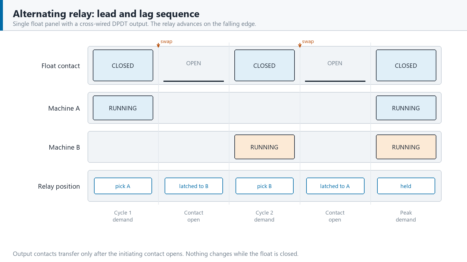
The swap happens on the off edge. While the float contact is closed, the selected pump runs and nothing changes.
When the level drops and the contact opens, the internal ratchet or magnetic latch advances one position, and the next closing picks the other pump. A mechanical unit holds that position through a supply failure, because the memory lives in the mechanism rather than in a capacitor or a register.
Cross-wired versions change the last step. A DPDT output with the transfer contacts wired across lets both machines run together once the lag float closes, while keeping the alternation for the next cycle. Eaton describes this arrangement on its duplex range as sequence on, simultaneous off, which is a clearer description than most: the two loads start in order and stop together.
| Cycle | Float state | Which machine runs | Relay position afterwards | What the LEDs show |
|---|---|---|---|---|
| Cycle 1, level rising | Lead float closes only, machine A starts, relay set to pick B next | Machine A | Latched towards B | One LED lit, marked A |
| Cycle 1, level falling | Lead float opens, machine A stops, relay advances one position | None | Holding on B | Both LEDs dark |
| Cycle 2, level rising | Lead float closes only, machine B starts, relay set to pick A next | Machine B | Latched towards A | One LED lit, marked B |
| Cycle 2, level falling | Lead float opens, machine B stops, relay advances one position | None | Holding on A | Both LEDs dark |
| Peak demand | Lead and lag floats both closed, cross-wired model required | Machine A and machine B | Alternation held until both stop | Both LEDs lit |
Table 1. Five states in one alternation cycle, written for a single float panel with a cross-wired output.
The table assumes something that catches people out. A plain unit counts cycles, not hours. Two short cycles and one long one still leave the pair uneven, and a wet well that fills for ninety seconds every ten minutes will drift however faithfully the relay swaps. Electronic duplexers with run time registers exist for exactly that case, and they cost noticeably more than a plug-in relay in an octal socket.
How Relays Alternating Duty Differs from a Standard Control Relay
A standard control relay follows its coil. Energise the coil and the contacts transfer, drop the coil and they return, as often as you like, with nothing remembered in between. Alternating duty breaks that rule on purpose. The coil is energised for a fraction of a second to advance a mechanism, and the contacts hold the new position after the pulse has gone. Supply can fail for an hour and the unit still knows which machine ran last.
That memory is mechanical on the cheaper units, a ratchet driven by the coil pulse, and magnetic or electronic on the rest. It changes how the coil circuit is sized. A coil quoted at 40 mA on a 120 V AC model sits near 3 VA of burden while it is energised, which is why the control transformer in a duplex panel is usually sized by the contactors rather than by the relay.
The name also covers two different devices. In lighting and general automation an alternating relay often means an impulse or step relay, where each pulse to the coil toggles one load on and off, the arrangement behind staircase lighting. In fluid control and HVAC the same phrase means the lead lag controller described here. Both rely on a latching mechanism. Only one of them has two outputs to swap between, which is why alternating relays for pump duty are never a drop in replacement for a lighting step relay.
Neither one is a protective relay. Nothing here measures current or voltage, nothing has a setting, and no trip coil is involved. Protection sits upstream in a motor protection relay, which is the device that decides a pump should stop because it has been drawing locked rotor current for too long. The alternator only decides which pump was asked to start.
Keep the two functions in separate boxes. Combining protection and duty rotation sounds tidy and makes both harder to test.
Choosing an Alternating Relay: Outputs, Coil Voltage and Ratings
Alternating relays come in three output configurations, and they cover most of the market. SPDT gives one contact set and one load at a time. DPDT gives two isolated sets. DPDT cross-wired gives two sets wired so a second float can bring both machines on together. Choose by float count before anything else: one float wants SPDT or DPDT, two floats want cross-wired, and three floats with a stop switch want the dedicated three input model.
Coil voltage follows the control circuit, and the usual catalogue covers 12 V, 24 V, 120 V and 240 V AC. Tolerance is commonly +10% to -15% at 50 Hz or 60 Hz, worth checking on any panel where a control transformer also carries contactor coils. Where a PLC drives the input, order the DC version and fit a flyback diode across A1 and A2, or accept that the driving transistor will not last.
Contact rating is where most specifications go wrong. The output switches starter coils, so the governing number is pilot duty, quoted against a utilization category such as AC-15 in IEC 60947-4-1:2023, or DC-13 where the starter coil is DC. A typical plug-in unit offers 10 A at 240 V AC resistive and 1/2 hp at 120 V AC, which is comfortable for a coil and hopeless for a 4 kW motor. Size the contacts to the coil inrush taken from the starter datasheet, then add margin.
Coil inrush is the number that welds contacts. A large contactor can pull five to eight times its sealed VA for the first few cycles, and an AC-15 rating quoted against a 3 VA burden means something quite different from the same rating against a 40 VA coil. Read the starter data rather than the motor nameplate.
Life figures separate the two technologies cleanly. Electromechanical units quote around 10,000,000 mechanical operations and 100,000 operations at full load, over an ambient range of roughly -28 °C to 65 °C. Solid-state versions drop the moving parts and add an adjustable delay, at the cost of a leakage current through the output that some contactor coils will hold in.
| Line on the datasheet | What it decides | Typical catalogue value | What goes wrong if nobody checks |
|---|---|---|---|
| Output configuration | How many loads can run together, and how many floats you can wire | SPDT, DPDT or DPDT cross-wired | A single float model cannot bring the lag machine on during peak demand |
| Control voltage | Which control circuit the coil sits on, and how far it may sag | 12 V, 24 V, 120 V or 240 V AC, tolerance +10% to -15% | A coil fed from a sagging transformer chatters and doubles the swap count |
| Contact rating | Whether the output can carry the starter coil inrush | 10 A at 240 V AC resistive, 1/2 hp at 120 V AC or 240 V AC | Contacts sized to the motor rather than the coil weld on the first start |
| Utilization category | The duty the rating was actually tested against | AC-15 for control coils, AC-3 only where a motor is switched directly | An AC-1 figure applied to inductive duty pits the contacts within one season |
| Debounce delay | Immunity to waves and splashing moving the float | 0.5 s on some models, 5 s on others | A short delay on a turbulent wet well swaps on every ripple |
| Socket and approvals | Whether the listing survives installation | 8 pin octal or 11 pin, UL 508 listing only with the matching socket | A listed relay in an unlisted socket is not a listed assembly |
Table 2. Six datasheet lines worth arguing about while the panel is still in detail design.

Wiring Alternating Relays and Proving the Swap
The coil side is a series circuit: control supply, the float or pressure contact, and A1 to A2. Nothing else belongs in it. Where the initiating device is a level float in a wet well, the contact lands on a marshalling terminal first, gets fused there, and crosses to the relay in 1.5 mm² stranded cable routed clear of anything carrying motor current. Induced noise on that core produces phantom swaps, and a phantom swap stays invisible until somebody notices the hours are still uneven.
The output side feeds starter coils, usually through an interlock taken from the opposite contactor so the two machines cannot be commanded together unless the design calls for it. Fit a suppressor across each coil. A varistor on AC and a diode on DC cost very little, and they spare the relay contacts the energy a coil dumps back into whatever opened it.
Protection on the power side needs a curve that tolerates inrush. A B curve breaker reads a motor starting surge as a fault and nuisance trips on the second machine every time it is asked to carry peak demand. C curve or D curve is the normal choice for pump motors, and the same argument applies when the overload range is picked.
Two cycles is the whole test for alternating relays, and it is the check most commissioning sheets leave out. Close the float contact and note which machine starts. Open it, close it again, and confirm the other one runs. A relay wired to transfer but never tested looks exactly like a relay that works.
One more state is worth recording before handover: the position the unit wakes up in. A mechanical ratchet keeps its place through a supply failure. An electronic one may restart on load A every single time, which on a plant losing power weekly decides whether the pair stays balanced at all.
- Prove the swap twice, in front of the client, and write down which machine led each cycle.
- Close both floats on a cross-wired model and confirm both machines genuinely run together.
- Trip the coil supply fuse on purpose and watch what the panel reports about itself.
- Measure the coil burden with the contact closed, then again while the output is transferring.
- Check the selector switch is left on alternate, not locked to one machine after servicing.
- Record run hours on both machines at handover, so drift has a baseline to be measured against.

Failure Modes That Only Show Up in Month Six
The failure nobody diagnoses is a relay that never alternates. The most common cause is a unit wired to the wrong contact, or a selector switch left locked to load A during commissioning and never put back, or a coil circuit fed from a contact that closes with the motor instead of with demand. Everything looks fine for a year. Then the lead machine comes out for a rebuild two years early, and the standby refuses to start because it has turned three times since handover. Alternating relays that never swap also never complain, so nothing on the panel tells you the rotation has stopped.
Contacts weld on the second most common route: a relay sized to the motor rather than to the coil, switching a contactor whose inrush nobody looked up. The symptom is a machine that keeps running after the float has opened, which operators report as a pump problem rather than a control one. Drift shows up differently. A unit with no debounce delay swaps on every wave in a turbulent tank, doubling the starts and wearing both machines faster than a fixed lead ever would have.
Heat matters more than most datasheets suggest. A control cabinet standing in direct summer sun reaches 55 °C inside, and a rating quoted at 40 °C does not hold there.
The cheap defence is a run hour meter on each machine and one log line a month. Two numbers that diverge mean the alternation has stopped, whether or not anybody can hear a fault.
Where an Alternating Relay Is the Wrong Tool
- Three or more machines share the duty. A two position unit has nowhere to go, so buy an electronic duplexer or put the rotation in the PLC with run time registers.
- Peak demand regularly exceeds one machine and the panel has only one float. Fit a cross-wired model with a lag input, or accept that the wet well rises during storms.
- The two loads are not identical. Alternation equalises starts, not duty, and a 4 kW pump sharing a header with a 7.5 kW pump will never wear evenly.
- The machine is safety related. Fire pump controllers are covered by their own standard for good reason, and duty rotation belongs outside the starting path.
- The relay would switch motor current directly instead of a starter coil. Contacts rated for pilot duty will not survive it, so put a contactor in between.
- Run time equalisation is written into a contract or an insurance condition. Cycle alternation cannot deliver hours, and the maintenance log will say so.

Conclusion
Alternating relays solve one problem, and they solve it for roughly the price of a socket: two identical machines should wear at the same rate, and the standby should be a machine somebody has seen running. Pick the output configuration from the float count, size the contacts to the starter coil rather than the motor, and prove the swap twice before handover. Where the duty needs hours instead of cycles, or three machines instead of two, buy the electronic duplexer rather than pushing a two position relay past what it can do.
Frequently asked questions
What does an alternating relay do?
It changes which of two identical loads starts first on each duty cycle. Every time the initiating float, pressure or level switch opens, the output contacts transfer to the other side, so run hours stay even across the pair and the standby machine gets exercised.
What is the difference between an alternating relay and a standard control relay?
A standard control relay follows its coil and remembers nothing between operations. Alternating duty holds its position after the coil pulse ends, using a mechanical ratchet or a magnetic latch. Supply can fail for an hour and the unit still knows which machine ran last.
Can one alternating relay work with two float switches?
Yes, if the output is DPDT cross-wired. The lead float starts the machine selected for this cycle and the lag float brings the second machine on when one cannot keep up. A plain SPDT model has no second input to receive.
What contact rating do I need?
Size the contacts to the starter coil, never to the motor. Look up the coil inrush in volt amperes from the starter datasheet, add margin, and check the rating is quoted against a utilization category such as AC-15 in IEC 60947-4-1:2023.
Can one alternating relay control three pumps?
Not directly. A two position alternator has only two outputs to swap between. Three machines need an electronic duplexer with run time registers, or a sequence written into the PLC.
Why does only one pump run when both floats are closed?
Because the output is not cross-wired. A single float SPDT or plain DPDT model can only ever command one machine at a time. Simultaneous demand needs the cross-wired DPDT arrangement and a second float input.
How do I test that the relay is actually alternating?
Run two demand cycles. Close the initiating contact, note which machine starts, open the contact, then close it again and confirm the other machine runs. Fit run hour meters as well, because drift shows up in the hours long before anything else looks wrong.
Related reading
- What a relay is and how the contacts are built. The device an alternator is derived from.
- Pump protection relay selection. Where the protection function behind these starters lives.
- Pump station automation and SCADA control. Where duty rotation moves once the load count grows.
- Transfer switch practice for standby sets. The same lead and lag thinking applied to sources.
Sources and standards
Nine published references sit behind the figures quoted above. Editions are listed because contact ratings, utilization categories and immunity levels all move between them.
| Source | What it covers | Type | Edition |
|---|---|---|---|
| IEC 60947-5-1:2024 | Control circuit devices and switching elements, the family this relay belongs to | Standard | 2024 |
| IEC 60947-4-1:2023 | Contactors and motor starters, including the AC-1, AC-3 and AC-15 categories | Standard | 2023 |
| IEC 60947-1:2020 | General rules for low voltage switchgear and controlgear assemblies | Standard | 2020 |
| IEC 61810-1:2015 | Electromechanical elementary relays, covering ratings and endurance testing | Standard | 2015 |
| IEC 61439-2:2020 | Power switchgear and controlgear assemblies built from factory tested parts | Standard | 2020 |
| IEC 61000-4-2:2008 | Electrostatic discharge immunity testing and levels | Test method | 2008 |
| IEC 61000-4-4:2012 | Electrical fast transient burst immunity for signal and supply ports | Test method | 2012 |
| IEC 61000-4-5:2014 | Surge immunity testing for lines exposed to switching and lightning | Test method | 2014 |
| ANSI/IEEE C37.2-2022 | Device numbers and function numbers used on drawings, which reserve none for alternation | Standard | 2022 |
Table 3. References used above, with the edition each figure was read from.
Catalogue values quoted above are the ranges our own build sheets ask for on duplex pump and compressor work. They are not limits set by any standard, and the datasheet governing your own equipment always wins.
For a quotation with drawings and a test certificate, send the feeder schedule.
Equipment used in alternating and lead-lag duty: PLC control panel for hydro and pumping stations; low voltage motor protection relay; common measurement and control panel.
About Author

Hello, I'm Leon Zhang. I have 15 years of experience in the power relay protection industry with extensive pre-sales and after-sales project experience. Our company specializes in various complete sets of relay protection and automation equipment. I can assist customers in solving all practical on-site project challenges and provide optimal integrated solutions.
Tell Us Your Requirement



High Quality
Stable performance, reliable design, ensuring safe operation for power system protection and grid stability.
Fast Delivery
Timely delivery to support your urgent orders and project schedules efficiently and professionally at any time.
Best Warranty
Professional Warranty: Reliable after-sales support for stable relay protection and long-term customer satisfaction.