
-
Leon Zhang sales consultant
-
Email: zxl635973785@gmail.com
-
Phone/WhatsApp: +86 13655813266
What Is a Relay Explained
What is a relay? A device that opens or closes one circuit on a signal from another. Five families, nameplate ratings, ANSI numbers, inrush limits and where they fail.
What is a relay? A relay, or relay switch, is a device that opens or closes one circuit on a signal from another, and almost every unit in a plant belongs to one of five families: electromechanical, solid-state, latching, time-delay, or measuring. Which family you need follows from load current, switching frequency, and whether the contact must hold its position through a power loss.
Written by Leon Zhang, Protection Application Engineer · Technical review by Li Ming, Electrical Engineer · Last reviewed October 2026
The five families, the nameplate vocabulary and the function-number system of ANSI/IEEE C37.2-2022 that labels protection units in a substation are mapped on this page. Sizing one device against one load is a separate job: the electrical relay selection guide carries the coil and contact tables, and the power relay ratings page covers motor and heater duty.
At a Glance
- Five families of relays cover nearly every panel: electromechanical, solid-state, latching, time-delay, measuring.
- Isolation is the point. A 24 V DC coil can switch a 400 V circuit with no metallic path between the two.
- Contact ratings are quoted at 23 °C ambient under IEC 61810-1:2015. A cabinet at 55 °C cannot carry the same current.
- AC-1 and AC-3 are different duties. AC-3 makes about 10 times rated current, which AC-1 never sees.
- DC has no zero crossing, so 220 V DC breaking capacity is a fraction of the AC figure at the same amperes.
- Silver contacts need wetting current. Below roughly 100 mA at 12 V, specify gold-flashed or dry-circuit contacts.
- ANSI/IEEE C37.2-2022 assigns 95 function numbers and 22 acronyms. 50/51, 87 and 27/59 cover most feeder work.
- A contactor is not a larger control device. It is built to make 10 times its rating under AC-3 (IEC 60947-4-1:2023).
What Is a Relay, and What Do Relays Do That a Plain Switch Cannot?
A relay splits the circuit that decides from the circuit that acts: a 24 V logic signal, a 5 A contactor coil, or a 1 A trip output can command a 400 A feeder with no metallic connection between the two. A plain switch needs a hand on it instead.
Isolation is the entire reason the device exists.
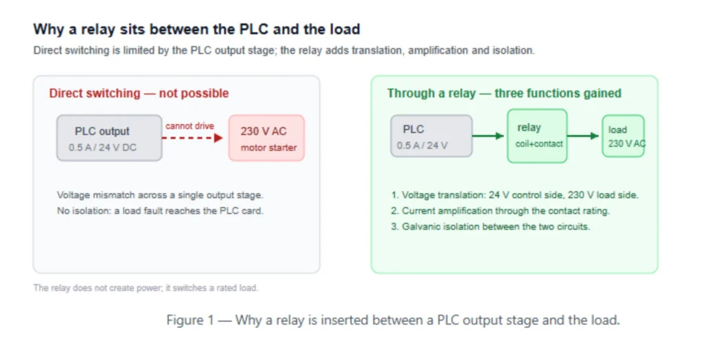
Four jobs follow from it. Isolation keeps a fault on the load side away from the control side. Amplification turns a 0.5 A output into a 10 A switching action. Multiplication gives one coil several independent contact sets, which is how a single command opens a motor circuit and closes a status contact at the same time.
Memory, in the latching version, keeps a position after the supply drops.
Protection relays use only the first of those jobs. The measuring unit reads CT and VT secondary values, compares them with a setting, and closes a trip output. The breaker carries and interrupts the fault current.
Nothing in the protection chain is expected to break 25 kA, and nothing in the breaker is expected to grade with the upstream device. Split that responsibility the other way and the scheme stops coordinating.
Rule of thumb for a control cabinet: if two circuits sit at different potentials, or one is a logic-level output and the other an inductive load, put a device between them. Direct connection is defensible only when both sides share a common supply and a common ground.
The Five Families and the Duty Each One Is Built For
What is a relay for? Most engineers answer switching, and the five families exist because the other three jobs, isolation, amplification and memory, pull the design in different directions. The choice inside those families is set by three numbers: load current, operations per hour, and whether the output must hold through a supply failure. Price comes fourth.
| Family | What moves | Typical duty | Number to check | Common failure |
|---|---|---|---|---|
| Electromechanical (EMR) | Armature and silver contacts | Signal and small load switching, 24 V DC to 230 V AC | Electrical life at rated load | Welded contacts after inrush |
| Solid-state (SSR) | Thyristor or MOSFET pair, opto-isolated | Heaters on PID control, high cycle rate | Thermal resistance with heatsink | Thermal runaway at partial load |
| Latching (bistable) | Permanent magnet or mechanical latch | Memory after power loss, remote reset | Coil pulse width | Stuck in its last state |
| Time-delay | Pneumatic bellows, motor, or electronic timer | On-delay, off-delay, star-delta changeover | Time range and repeat accuracy | Drift after years at 55 °C |
| Measuring (protection) | Static or numerical comparator | CT and VT inputs, ANSI coded functions | Accuracy class and CT burden | Nuisance trip from a wrong CT ratio |
Duty cycle decides more than price. A small EMR rated 100,000 electrical operations at rated load is used up in 28 hours at one operation per second; an SSR in the same socket runs for years. Divide the expected operations by the rated life before comparing two quotations.
Unlike an EMR, an SSR has no contact to weld. It does drop 1 to 1.5 V across the output, so a 10 A load burns 10 to 15 W inside the cabinet, and that heat is a panel design problem rather than a datasheet footnote.
Where the load sits on a substation panel rather than a machine, the choice usually narrows to measuring relays. Our numerical protection devices are grouped by ANSI function for that reason: 50/51 feeder units, 87 differential units, and 27/59 voltage units share a form factor but not a setting philosophy.
What Is a Relay Nameplate Telling You, and How Do You Read It?
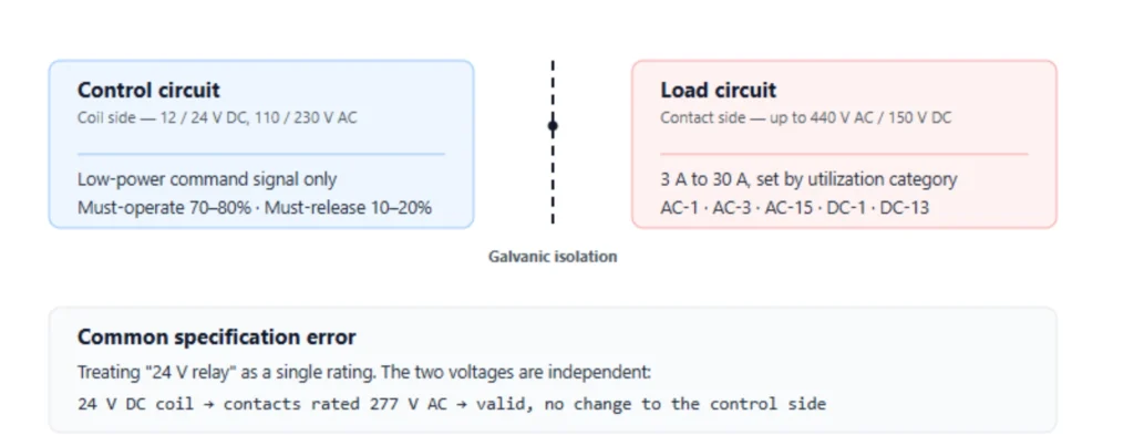
Two numbers decide whether a device fits: coil voltage, which must match the control supply, and contact rating, which must be read at the utilization category of the actual load. Everything else on the label is secondary.
Coil and Contact Are Independent Circuits
A coil rated 230 V AC will not work on 230 V DC. Same number, different physics: the AC coil relies on impedance that a DC supply does not present. On the DC side, a 24 V coil normally must see about 75% of nominal before it picks up, so 19 V on a 24 V coil is marginal rather than acceptable.
Coil duty is the line most often skipped. A continuous-duty coil holds at nominal voltage indefinitely. An intermittent-duty coil is built for a percentage on-time, and leaving it energized beyond that rating overheats the winding within an hour at 40 °C ambient, which reads as a failed device rather than a selection error.
Contact side, read the letters before the amperes. NO means open at rest, NC means closed at rest, COM is the common terminal they share. A changeover contact carries all three. Terminal numbers follow the same logic across most DIN-rail product lines: A1 and A2 for the coil, 11-12-14 for a changeover, 21-22-24 for a second one.
The Utilization Category Decides the Current
AC-1 is resistive load. AC-3 is squirrel-cage motor duty, and the making current under AC-3 is about 10 times rated (IEC 60947-4-1:2023). AC-15 covers control circuits such as coils and solenoids. DC-13 covers DC electromagnet loads.
A headline figure with no category next to it is usually AC-1 at 23 °C, which says nothing about a 10 A motor.
Temperature enters the same way.
The 23 °C reference is fixed by IEC 61810-1:2015, and every datasheet carries a derating curve above it. If the panel interior runs at 55 °C in summer, the nameplate current is not available, and the gap widens further when several devices sit side by side in a row.
What Do the ANSI Device Numbers Mean?
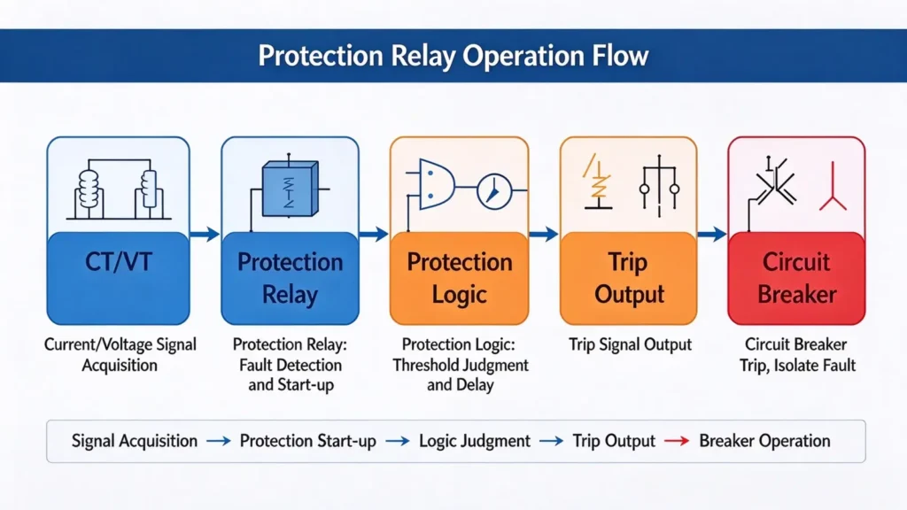
ANSI/IEEE C37.2-2022 assigns 95 function numbers and 22 acronyms, and a number describes a function rather than a box. One numerical terminal on a feeder carries 50, 51, 50N, 51N and 79 inside a single case, which is why the drawing shows five numbers at one location.
| Number | Function | Where it is set |
|---|---|---|
| 21 | Distance protection | Transmission and sub-transmission lines |
| 25 | Synchro-check | Generator and tie-breaker closing |
| 27 / 59 | Undervoltage / overvoltage | Bus and motor terminals |
| 32 | Reverse or directional power | Generator prime mover, tie lines |
| 40 | Loss of excitation | Generators with static excitation |
| 46 | Negative sequence current | Generators and large motors |
| 49 | Thermal overload | Transformers and motors |
| 50 / 51 | Instantaneous / time overcurrent | Any feeder or transformer |
| 50N / 51N | Earth fault overcurrent | Grounded systems |
| 64 | Earth fault on machine winding | Generator rotor and stator |
| 86 | Lockout (trip and blocking) | Station trip and blocking circuits |
| 87 | Differential | Transformer, generator, motor, busbar |
Suffixes carry the zone, not the function. 87T is a transformer differential, 87G a generator differential, 87M a motor differential, 87B a busbar differential. Two drawings that both read 87 can describe four different protection zones, and a scheme review that ignores the suffix will miss the boundary between them.
A code is not a product name.
Two suppliers can both sell 50/51 and differ in curve shape, reset ratio and communications, and those differences decide whether the scheme grades with the utility incomer. The full list of ANSI device numbers covers the remaining numbers and the contact designations that go with them.
Where Relays Sit in a Plant
What is a relay doing at each layer of a plant? Switching the same way, at four different voltages and fault levels: 24 V interface between PLC and field, LV motor control, MV protection with CT and VT inputs, and the station DC trip circuit. Each layer has its own test routine.
| Layer | What it does | Voltage and current | Test before energizing |
|---|---|---|---|
| Field interface | Separates PLC outputs from coils, solenoids and lamps | 24 V DC, 0.1 to 5 A | Suppression fitted, polarity checked |
| LV motor control | Starts and stops motors with overload protection | 400 V AC, up to hundreds of amperes | AC-3 rating against motor FLC |
| MV protection | Detects faults from CT and VT inputs, trips the breaker | 110 V DC circuits, CT secondary 1 A or 5 A | Injection test, grading check |
| Station DC and trip | Locks out after a trip, supervises the trip coil circuit | 110 or 220 V DC | Trip circuit supervision alarm |
Interposing matters at the first layer because a PLC output card switches roughly 0.5 A at 24 V DC. The kickback from a 5 A contactor coil reaches several hundred volts and will puncture the output transistor, so the interface device between card and coil is not optional.
A socketed interface device also gives maintenance a cheap part to replace instead of a card.
The fourth layer is where most commissioning time goes.
A trip circuit carries 110 V DC for a few milliseconds a year, so supervision matters more than current rating. A supervision function passes a small current through the trip coil continuously and raises an alarm when that path opens: blown fuse, loose terminal, open coil winding. Without it, the first sign of a dead trip circuit is a breaker that stays closed during a fault.
Trip-circuit failures are quiet.
A wrong protection setting trips a feeder and somebody investigates within the hour. A wrong interface device fails intermittently for a year before anyone traces it to a coil that was switched without suppression.
Relays, Contactors, Breakers, or PLCs: Which One Does the Job?
What is a relay for, next to a contactor, a breaker and a PLC? The answer changes with the duty, and the fastest way to the right part is to name the job in one sentence, then match it against the switching duty rather than against the load size. Four candidate devices cover nearly everything an industrial panel needs.
| Job | Part | Because |
|---|---|---|
| Switch a 5 A control load from a logic signal | EMR, 1 or 2 changeover contacts | Cheap, isolates, several contacts per coil |
| Start a 15 kW motor | Contactor with overload | AC-3 rated to make 10× rated current |
| Interrupt a 25 kA fault | Breaker or fuse | Rated breaking capacity, not switching life |
| Sequence six steps with timers and interlocks | PLC plus output devices | Logic belongs in software, not in a coil |
| Trip a feeder with grading to the incomer | Numerical protection unit | Curves, CT inputs and event records |
| Hold a state through a power failure | Latching device | Mechanical memory, no holding current |
Two thresholds settle most arguments.
If the load exceeds 16 A, or the load is a motor, the answer is a contactor rather than a bigger control device. If the requirement is to break fault current, only a part with a rated breaking capacity qualifies, and a switching device has none.
Contactor and control device look alike on a DIN rail, and the difference is not the size of the terminals. It is the making current each one survives: 10 times rated under AC-3 for the contactor, against a fraction of that for a control-rated contact.
Panel builders who need the switching devices and the enclosure assembled to one drawing can order both as a protection and control panel.
Why Do Contacts Weld, and at What Current?
Contacts weld on make, not on break.
An incandescent lamp draws 10 to 15 times its running current for the first 10 ms, a capacitor bank more than that, and a resistive heater nothing at all. The rating that fails is the steady-state one.
Three load types cause most of the damage. Capacitive loads (LED drivers, power supplies, capacitor banks) charge an empty capacitor at the moment of closing, and the current is limited only by the circuit impedance. Motors draw locked-rotor current, about 6 to 8 times rated, until the rotor accelerates.
Incandescent lamps change resistance by a factor of 10 as the filament heats.
Compare the inrush, not the running current.
If a panel feeds a bank of LED drivers with 20 times inrush, a 10 A AC-1 contact is the wrong selection even though the steady current is 4 A. The same device that works on a resistive heater will weld closed on that driver bank within a year of daily switching.
Contact material follows the load. Silver-nickel suits general AC switching. Silver-tin-oxide resists welding better and is the usual choice for high-inrush loads such as capacitor banks and LED drivers. Tungsten faces appear where DC arcs are expected, because tungsten keeps its shape at arc temperature.
A supplier who quotes one material for every application has not read the load list.
DC loads add a second problem.
There is no zero crossing to extinguish the arc, so the arc sustains until the gap is wide enough. That is why a contact rated 10 A at 250 V AC is often rated 1 A or less at 220 V DC.
That sustained arc is also why DC-rated devices carry magnetic blowout, which pushes the arc sideways into a splitter plate.
At the other end of the scale, low-level signals fail differently.
Silver contacts form a sulfide film in an industrial atmosphere, and a 10 mA at 12 V signal cannot break through it. Gold-flashed or dry-circuit contacts are the fix, and the boundary is roughly 100 mA or 12 V: below either figure, specify them.
What Do You Check Before Energizing a Panel Full of Relays?
Four checks catch most of what commissioning would otherwise find, and none of them need the plant running. They are listed in the order the panel is built, because a check skipped at the base is a check that needs the door off later.
- Measure coil voltage at the terminal, not at the power supply. A 24 V coil that sees 19 V picks up and drops out again under vibration.
- Confirm suppression is fitted at the coil itself. A suppressor at the earth bar protects the wire run and nothing else.
- Match the contact rating against the inrush figure, and write the utilization category on the schedule rather than the amperes.
- Prove the trip circuit supervision alarm by opening the path on purpose and watching the annunciator respond.
Socketed construction makes the first three quick: pull the device, measure at the base, refit. A sealed or soldered part turns the same check into a rewiring job, which is why maintenance teams specify sockets even where the unit price is higher.
One check belongs on the schedule and rarely appears on it. Record the ambient temperature inside the enclosure at the hottest hour of a summer day, because every rating above 23 °C is a derated rating.
What Is a Relay Coil Suppressor For, and What Happens Without One?
A 24 V DC coil stores energy in its magnetic field. Interrupt the current and the field collapses in microseconds, driving the terminal voltage to several hundred volts. That transient destroys PLC outputs and erodes the very contacts that switched the coil.
Three suppressors are common, and they are not interchangeable.
A diode across the coil is cheapest and clamps at about 0.7 V in the reverse direction, but it also circulates current through the coil and adds 5 to 10 ms of release delay. An RC network releases faster and costs more.
A varistor clamps at a higher voltage and releases fastest of the three.
AC coils behave differently and need no diode. Their current crosses zero twice per cycle, so little energy remains at interruption, and an RC network covers the transient. Fitting a diode across an AC coil, which happens when a panel is copied from a DC drawing, short-circuits the coil on the reverse half-cycle and burns the contact that feeds it.
Fit the suppressor at the coil terminals, not at the panel earth bar and not at the PLC card. A diode in a safety or interlock circuit can turn a 6 ms drop-out into 15 ms, and that delay sits directly in the stopping time of a guard.
Where release time is specified, an RC or a varistor is the correct part, and the datasheet curve shows why.
What Belongs in an RFQ
Six lines prevent most wrong orders: coil voltage and tolerance, contact configuration and count, load type with its inrush figure, operations per hour and target life, ambient temperature inside the enclosure, and the standard or certification the project requires.
Add terminal type and mounting if the panel is already drilled.
“24 V 10 A” on its own is not a specification, because it leaves out the load type that decides the rating. The electrical relay selection guide carries the full data sheet list, including the utilization category fields that suppliers need before they can quote a life figure.
Where Relays Are the Wrong Answer
What is a relay not for? Four situations call for something else. Choosing a general-purpose switching device in any of them produces an intermittent failure rather than an immediate one, which is the harder kind to diagnose.
- Safety functions. A guard interlock or an emergency stop needs a certified device with forcibly guided contacts (IEC 61810-3:2015) and a validated architecture under ISO 13849-1:2023 or IEC 62061:2021. A general-purpose device has no diagnostic coverage claim.
- DC breaking above 220 V DC. Without magnetic blowout the arc sustains, and the device’s DC rating may be a tenth of its AC rating. Use a DC-rated breaker or a contactor with blowout.
- Continuous high cycle rate. Above roughly one operation per second, an EMR’s electrical life becomes the maintenance schedule. An SSR moves the limit to the heatsink.
- Revenue metering. A switching device is not a meter: accuracy class under IEC 62053-22:2020 belongs to a dedicated meter, and no switching contact has a defined accuracy class at all.
One more boundary is less obvious. An EMR in a circuit that is energized but never switched will still fail, because silver contacts degrade in an industrial atmosphere with no wiping action to clean them.
If the contact must sit closed for years, a sealed or gold-flashed version lasts longer than the standard part.
Frequently Asked Questions
1. What is a relay in simple terms?
An electrically operated switch: a control signal moves a contact, and that contact switches a separate circuit the control side never touches electrically.
2. What is a relay used for in a protection panel?
Measuring, judging and tripping. The device compares CT and VT secondary values with a setting and closes a trip output, while the breaker carries and interrupts the fault current.
3. What is the difference between relays and contactors?
Duty, not size. A contactor is rated to make and break motor current under AC-3, about 10 times its rated current, for hundreds of thousands of operations. A control device is rated for control-circuit loads, typically a few amperes, and it carries several contact sets for logic.
Using one where the other belongs shows up as welded contacts within weeks.
4. Can a 24 V DC device switch a 230 V AC load?
Yes, if the contact is rated for it. Coil voltage and contact voltage are independent specifications: a 24 V DC coil can drive a contact rated 250 V AC. What must match is the contact rating against the load, including its inrush and its utilization category.
The coil voltage alone never decides the load side.
5. What do NO, NC and COM mean?
NO is open at rest and closes when the coil is energized. NC is closed at rest and opens on energizing. COM is the common terminal shared by both. A changeover contact provides all three, and terminal numbers 11, 12 and 14 are the usual marking on DIN-rail product lines.
For a signal that must report a failure, wire the NC path: a broken wire looks the same as a tripped device, which is the safe direction. Our protective device functions follow the same convention on trip outputs.
6. How long does an electromechanical unit last?
Two lives, and both are quoted separately. Mechanical life runs into tens of millions of operations with no load. Electrical life at rated load is far shorter, commonly 100,000 operations for a small device switching its rated current.
The number that matters is the electrical one at the current you actually switch, read from the derating curve.
7. What is the difference between latching and non-latching?
A latching device keeps its position after the coil supply is removed, using a permanent magnet or a mechanical latch. A non-latching device drops out when the coil loses power. Latching is the right choice where the state must survive a supply failure without a battery, and the wrong choice where a de-energized panel must return to a known safe state.
8. Why does a solid-state unit need a heatsink?
Because it dissipates power as heat, not as a spark. An SSR drops 1 to 1.5 V across its output, so a 10 A load produces 10 to 15 W inside the enclosure. That heat raises the junction temperature, and the current rating on the label assumes a case temperature the device will not reach without a heatsink.
9. Is a suppression diode needed on every DC coil?
On every DC coil switched by a semiconductor, yes. A PLC output or a transistor driver will fail without it. On a coil switched by a mechanical contact, suppression extends contact life rather than preventing immediate failure. Where release time is specified, a diode is the wrong choice and an RC or varistor goes in its place.
Conclusion
What is a relay, once the datasheets are set aside? A switch that lets one circuit command another, chosen on three numbers: duty cycle, inrush, and ambient temperature inside the enclosure. Read the nameplate against the load rather than against the load’s running current. Coil voltage decides compatibility with the control supply, nothing more.
After that, most of the engineering sits in the details that never appear in a quotation: suppression at the coil, interposing between PLC and contactor, and a utilization category that matches the actual load. Those three items account for more panel failures than any component defect.
For projects that need the switching device, the protection unit and the enclosure from one drawing, our engineering team reviews the scheme before the bill of materials is fixed, and the CT ratio assumptions are checked against the grading study rather than against the catalogue.
Related Reading
- Electrical relay selection: coil, contact and life data
- Power relay ratings for motor and heater loads
- ANSI device numbers and contact designations
- IEEE C37.2 standard for electrical power system device function numbers
Technical References and Sources
| Source | What it covers | Type | Edition |
|---|---|---|---|
| ANSI/IEEE C37.2 | Device function numbers and acronyms used to label protection functions | Standard | 2022 |
| IEC 61810-1 | Electromechanical elementary switching devices, general and safety requirements, ratings referenced to 23 °C | Standard | 2015 |
| IEC 61810-3 | Devices with forcibly guided (mechanically linked) contacts | Standard | 2015 |
| IEC 61812-1 | Time-delay and coupling devices for industrial and residential use | Standard | 2023 |
| IEC 62314 | Solid-state switching devices, safety requirements | Standard | 2022 |
| IEC 60255-1 | Measuring and protection equipment, common requirements | Standard | 2022 |
| IEC 60947-4-1 | Contactors and motor-starters, AC-3 making and breaking duty | Standard | 2023 |
| ISO 13849-1 | Safety-related parts of control systems, performance level (PL) architecture | Standard | 2023 |
| IEC 62061 | Functional safety of safety-related control systems, SIL allocation | Standard | 2021 |
| IEC 62053-22 | Static meters for AC active energy, accuracy classes 0.1S to 0.5S | Standard | 2020 |
About Author

Hello, I'm Leno Zhang. I have 15 years of experience in the power relay protection industry with extensive pre-sales and after-sales project experience. Our company specializes in various complete sets of relay protection and automation equipment. I can assist customers in solving all practical on-site project challenges and provide optimal integrated solutions.
Tell Us Your Requirement
High Quality
Stable performance, reliable design, ensuring safe operation for power system protection and grid stability.
Fast Delivery
Timely delivery to support your urgent orders and project schedules efficiently and professionally at any time.
Best Warranty
Professional Warranty: Reliable after-sales support for stable relay protection and long-term customer satisfaction.