
-
Leon Zhang Sales Manager
-
Email: sale@relayprotect.com
-
Phone/WhatsApp: +86 13655813266

Case Study: Complete Protection and Control Panel Supply for a 110kV Substation in Uzbekistan
What does a protection and control panel supply include for a 110kV substation?
A protection and control panel supply for a 110kV substation is the complete secondary lineup that protects, meters and controls every bay, delivered as one matched set rather than five cubicles that meet for the first time on site. This Uzbekistan order covered five panel types: AC and DC distribution, revenue metering, central alarm and annunciation, main transformer protection and transmission line protection. The drawings arrived written for another manufacturer’s hardware, so terminal layout, protection logic and the communication map were re-engineered before a wire was cut; that step, not assembly, set the delivery date. Device numbers follow ANSI/IEEE C37.2-2022 (21, 49, 50/51, 51N, 67, 79, 87T). Relay type testing follows IEC 60255-1:2022, assemblies IEC 61439-2:2020, enclosures IEC 60529, and the station bus IEC 61850-8-1 with Modbus. Every cubicle ran factory acceptance testing before the consignment shipped. Setting review and quotation within 12 hours, MOQ 1, 7-15 working days.
Protection and control panel supply for a 110kV substation in Uzbekistan covered five panel types: AC/DC distribution, energy metering, central alarm and annunciation, main transformer protection and transmission line protection. We re-engineered the customer’s own drawings around our relays, built the panels, ran factory acceptance testing on every cubicle and shipped the lot as one consignment.
The order was not a like-for-like swap. The drawings that came with the enquiry were written for another manufacturer’s hardware, so terminal layout, protection logic and the communication architecture all had to be redrawn before a single wire was cut. That re-engineering step, not the assembly, is what decided the delivery date.
The drawings set the schedule.

At a Glance
- Station: 110kV power distribution substation, local utility with an EPC contractor.
- Panels supplied: AC/DC distribution, energy metering, central alarm and annunciation, main transformer protection, transmission line protection.
- Transformer functions: 87T differential, 50/51 overcurrent, 51N earth fault, 49 winding temperature.
- Line functions: 21 distance, 67/67N directional overcurrent and earth fault, 79 auto-reclose, plus fault recording.
- Engineering: original drawings re-issued against our relays; terminal plan, wiring diagrams and communication architecture redrawn.
- Verification: full FAT before shipment covering wiring, protection function, IEC 61850 and Modbus links, alarm and signal.
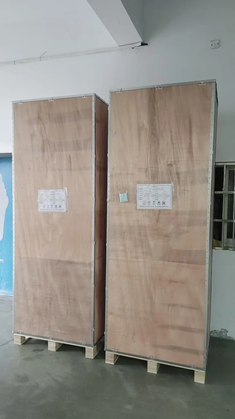
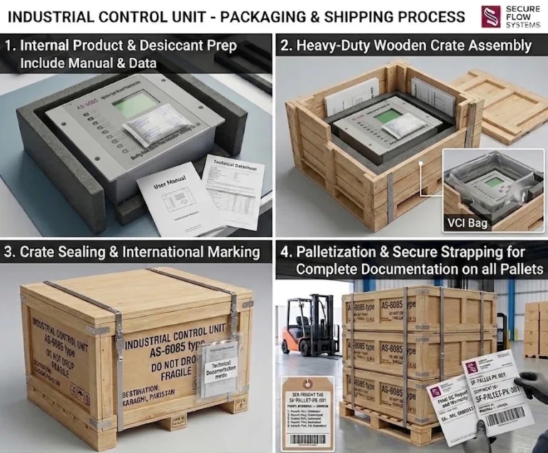
- Packing: export wooden cases with moisture barrier, desiccant and shock filler for sea and land legs.
- Standard frame: device numbers per ANSI/IEEE C37.2, relays and testing to IEC 60255, assemblies to IEC 61439.
Device numbers follow ANSI/IEEE C37.2-2022. Relay performance and type testing follow IEC 60255-1:2022, panel assemblies are rated to IEC 61439-2:2020, enclosure protection to IEC 60529, and the station bus runs IEC 61850-8-1 alongside Modbus.
Project Overview
The station is a 110kV distribution substation feeding urban, industrial and rural load. One order covered the whole secondary scope, so the panel lineup had to arrive as a matched set rather than as five independent cubicles that meet on site for the first time.
Basic Project Information
Selecting a relay for a live project?
Send the system voltage, CT ratio and tripping scheme. Our engineers confirm the model and reply within 12 hours.
| Item | Description |
|---|---|
| Country | Uzbekistan |
| Voltage Level | 110kV |
| Application | Power Distribution Substation |
| Scope of Supply | Protection, Control, Metering and DC System Panels |
| End User | Local Power Utility & EPC Contractor |
| Delivery Mode | Engineering Design + Manufacturing + FAT + International Shipment |
What a 110kV Substation Control Panel Has to Do
A 110kV substation control panel carries four jobs at once, and they pull in different directions. It has to clear faults fast, it has to interlock switching so an operator cannot close into a fault, it has to meter what the station buys and sells, and it has to push status and alarms up to SCADA. A panel that does the first job well and the fourth badly will pass its own type tests and still fail commissioning.
Each protection and control panel in the lineup is where those four jobs meet. Which one wins the argument is settled by the setting sheets, not by the brochure.
On this project the four jobs were split across dedicated cubicles instead of being crowded into one:
- Protection in the transformer and line panels, with trip outputs hardwired to the breaker coils.
- Control and interlocking in the same panels, driven from the bay level and mirrored to the station HMI.
- Revenue metering in a separate panel, so meter seals and test blocks stay away from the trip wiring.
- Alarm and annunciation in a central panel, which is what the operator actually looks at first.
Scope of Supply
The protection control panel supply was engineered as one scope against the 110kV single line diagram, so every bay shares the same CT and VT conventions, the same trip supply and the same substation communication map. Five panel types came out of that scope.
AC/DC Distribution Panels
AC and DC distribution panels serve as the core station service power supply for the entire substation. They deliver stable auxiliary power to protection relays, control devices, communication modules, lighting and other on-site equipment, ensuring uninterrupted operation of all secondary systems under various working conditions.

Energy Metering Panels
The revenue metering system on these panels measures, totals and records consumption in real time, which is what the utility settles against. Meters sit on a high-precision metering panel with its own test block, so a meter can be checked or replaced without disturbing the trip circuits on the protection panels.

Central Alarm and Annunciation Panels
Central alarm and annunciator panels enable centralized monitoring of all operating status and fault signals of the substation. Once abnormal conditions or faults occur in primary and secondary equipment, the system will trigger timely sound and light alarms and record event information, helping on-site staff quickly locate problems and carry out troubleshooting.
Main Transformer Protection Panels
The main transformer protection panels carry 87T biased differential as the main scheme, 50/51 overcurrent for through-fault backup, 51N earth fault and 49 winding temperature supervision. The differential element is a differential protection relay with CT matching and inrush restraint, so it stays stable on energisation and still trips for internal turns faults. Setting the overcurrent stage is its own exercise; the method is set out in how to set an overcurrent relay, and the earth fault element was graded against the downstream feeder protection rather than set on a rule of thumb.
Transmission Line Protection Panels
Built for the 110kV feeders, these line protection panels carry 21 distance protection as the main scheme, with 67 and 67N directional overcurrent and earth fault as backup, 79 auto-reclose for transient faults and a disturbance record for post-fault review. The distance element comes from our distance protection relay range, and where a feeder needs unit protection instead, the panel takes a line differential relay on the same frame. On a short circuit or ground fault the relay trips the faulty section and, where the fault was transient, closes back in; the event goes to the fault recorder and up to the station level. See also transmission line protection relays for the scheme choices behind each function.
Protection and Control Panel Functions by Panel
The same function number means the same thing on every drawing, which is what kept the re-engineering review short. Here is what landed on each panel:
| ANSI | Function | Panel | What it clears |
|---|---|---|---|
| 87T | Transformer biased differential | Main transformer | Internal phase and inter-turn faults inside the tank |
| 50 / 51 | Instantaneous and IDMT phase overcurrent | Main transformer | Through faults, and backup for downstream protection that fails to clear |
| 51N | Earth fault | Main transformer | Single phase to earth on the winding or terminals |
| 49 | Thermal replica / winding temperature | Main transformer | Sustained overload and loss of cooling |
| 21 | Distance | Transmission line | Phase faults on the 110kV feeder, in zones, without waiting for a remote signal |
| 67 / 67N | Directional overcurrent and earth fault | Transmission line | Faults in the forward direction only, so reverse faults do not trip this bay |
| 79 | Auto-reclose | Transmission line | Transient faults, by closing back in after the arc de-ionises |
| 50BF | Breaker failure | Both | A breaker that refuses to open; trips the upstream source instead |
50BF is the one that gets dropped when a schedule tightens, and it is the one an EPC contractor asks about during design review. It stays in.
Engineering Challenges Faced by the Customer
Three constraints came out of the first technical meeting, and each one had to be closed before drawings could go to the workshop.
Challenge 1: Inconsistent Original Drawings and Hardware Configuration
The drawings the customer sent were written for other brands of equipment. Internal hardware structure, component layout and signal distribution all differed from ours. Building straight from those sheets would not have produced a panel that matches our standard products, so the design was reworked end to end.
Challenge 2: Strict Requirements for System Compatibility
The customer looked at the lineup as one system, not five cubicles. Protection logic that disagreed across bays, wiring that did not follow the stated convention and communication protocols that would not talk to the existing SCADA were all ruled out on paper first. Coordination between panels is decided by the setting sheets and the signal list, and both were fixed before assembly started.
Challenge 3: Tight Project Schedule
The substation construction progress was tight. The customer required rapid technical review, efficient production and guaranteed on-time delivery, putting forward high requirements for our engineering efficiency and production capacity.
Our Engineering Solution
Work ran in three passes: read what the customer sent, rebuild it against our hardware, then submit and get it signed off.
Detailed Drawing Review and Optimization
Step 1: Full Analysis of Technical Documents
Engineers read every document the customer sent: single line diagrams, protection schematics, terminal layouts and cable schedules. Parameters, logic requirements and wiring rules were pulled into one list, which became the reference for every later change.
Step 2: Professional Re-engineering and Adaptation
The original design was not copied. Protection schemes were rebuilt around the relays we actually ship, then the terminal arrangement, internal wiring and communication architecture were redrawn to match. Every function the customer specified stayed in; only the hardware path changed.
Step 3: Drawing Submission and Final Approval
General arrangement, wiring, terminal and communication drawings went to the customer once internal checks came back clean. They were approved as submitted, which released the panels to the workshop.

Manufacturing Process
Assembly followed the approved drawings, with inspection at each stage rather than only at the end. Every protection and control panel in the order was checked between processes, not only at FAT.
Rework happened here, not on site.
Fitters built the cubicles, ran the main bus wiring and installed terminals to the confirmed drawings. Relays, metering devices and communication modules went in after, wired to the terminal plan.
Once assembled, inspectors checked mechanical construction, walked every circuit against the drawings and verified ferrule and label numbering. Faults went back for rework before the panel entered formal testing.
Factory Acceptance Testing (FAT)
Factory acceptance testing is the last point at which a panel can be fixed before it is on a ship. Every cubicle went through the full sequence, and the reports went to the customer with the shipping documents.

- Wiring Verification: Every circuit was inspected one by one to ensure standard wiring and correct connection.
- Protection Function Testing: We fully tested differential protection, overcurrent protection, earth fault protection and breaker failure logic, and all protection actions were accurate and reliable.
- Communication Testing: Verified the compatibility and stability of IEC 61850, Modbus and other mainstream communication protocols to guarantee smooth data interaction with the substation SCADA system.
- Alarm and Signal Verification: Tested central alarm linkage, remote status indication and event recording functions, all of which operated normally as designed.
| Test | Method | Acceptance criterion |
|---|---|---|
| Wiring verification | Point-to-point check against the approved wiring diagrams | Every circuit agrees with the drawing; ferrule and label numbers match the terminal plan |
| Protection function | Secondary injection at the panel test block | Pickup, operating time and trip output agree with the approved setting sheet, including 50BF logic |
| Communication | IEC 61850 and Modbus link test to the station SCADA | Data points, report control and time synchronisation come up and stay up; no manual retry |
| Alarm and signal | Simulated fault and status inputs | Annunciator, remote indication and event record fire in the designed sequence |
| Mechanical and label check | Visual inspection against the general arrangement drawing | Enclosure, degree of protection, earthing and labelling match the approved GA |
The reports travelled with the panels.
The FAT record below is what those reports contain: what was tested, how, and what the panel had to do to pass.
Packing and International Shipment
For export transportation, we adopted export-standard wooden cases for packaging. Moisture-proof films, desiccants and shockproof fillers were used inside the packages to prevent equipment from being damaged by dampness, collision and vibration during long-distance sea and land transportation.
All goods were loaded and shipped as scheduled, with shipping documents and technical documents attached. Customs clearance depends on that paperwork being complete, and it was.
Everything arrived intact.

Why International EPC Contractors Choose Us
Four things decide whether an EPC contractor re-orders: whether the drawings come back right, whether the whole secondary scope is on one purchase order, whether the protection and control panel tests clean, and whether the supplier has shipped to that region before.
Strong Professional Engineering Team
Our engineering team has rich experience in international power projects. We are capable of drawing re-design, protection scheme customization and technical adaptation strictly in accordance with IEC international standards, and can respond quickly to various personalized design demands from customers.
Complete Product Portfolio
Protection relays, control panels, metering panels, AC/DC distribution and the communication layer all come from the same catalogue, so one purchase order covers the secondary scope and one set of drawings governs it.
Reliable Manufacturing & Quality Control
Standardised workshops and a written quality system keep repeat orders on a short cycle. Each panel is inspected between processes and functionally tested at the end, which is also what makes the FAT reports repeatable from lot to lot.
Rich Overseas Project Experience
We have served a large number of utility substations, renewable energy power plants and industrial power system projects across Central Asia, Southeast Asia, the Middle East and Africa. We are familiar with overseas project processes, export standards and technical requirements, and can provide full-process support from design to after-sales.
Frequently Asked Questions (FAQ)
Can you redesign drawings based on your own protection relays?
Yes. Send the single line diagram, protection schematics, terminal layouts and cable schedules, and engineers will rebuild the scheme against the relays we ship. Function requirements stay exactly as specified; what changes is the hardware path, the terminal plan and, where needed, the communication architecture. You get general arrangement, wiring, terminal and communication drawings back for approval before anything is built.
Can you provide complete protection and control panels for substations?
Yes. One order can cover protection panels, control panels, metering panels, AC/DC distribution panels and the central alarm and annunciation panel, which is what this 110kV project did. Keeping the secondary scope on a single purchase order means one set of CT and VT conventions, one trip supply philosophy and one signal list across every bay, and it removes the interface arguments that appear when two suppliers meet at the marshalling box.
Do you perform Factory Acceptance Tests before shipment?
Yes, on every export order. The sequence covers wiring verification, protection function testing by secondary injection, IEC 61850 and Modbus communication to SCADA, alarm and signal verification, and a mechanical and labelling check against the approved general arrangement. Test reports travel with the shipping documents. You can witness the FAT in person or by video, and commissioning spares and setting sheets ship with the panels.
Can your panels support IEC 61850 communication?
Yes. IEC 61850-8-1 over station bus and Modbus over serial or TCP are both supported, which covers the SCADA installations we see on export substations. Data points, report control blocks and time synchronisation are tested during FAT rather than left to site. Trip outputs remain hardwired to the breaker coils, so a communication fault cannot block a trip.
What drawings do you need to start a panel re-design?
The single line diagram, protection schematics, equipment terminal layouts and cable schedules are enough to start. Add the setting sheets if you have them and the SCADA point list if the bay has to report to an existing station. Where drawings describe another manufacturer’s hardware, the terminal plan and internal wiring get redrawn against our relays, so expect one review round before approval.
Which standard are the panel assemblies built to?
Assemblies are rated to IEC 61439-2:2020, with enclosure protection classified to IEC 60529. Relays and their testing follow IEC 60255-1:2022, and device numbers on the drawings follow ANSI/IEEE C37.2-2022. If your specification calls for a different assembly standard or a particular IP rating at the cable entry, say so at enquiry stage because it changes the cubicle design, not just the label.
Conclusion
This substation panel case study ends where most projects actually begin: with drawings that describe somebody else’s hardware and a schedule that does not move. The sequence that worked here was re-engineering first, approval second, then assembly and FAT, with the same signal list governing every cubicle.
The same scope applies at 35kV, 66kV, 110kV and 220kV, and for renewable plants that need a substation interface. What changes with voltage is the scheme and the CT and VT classes, not the workflow.
To get a firm quotation, send the single line diagram, the protection and metering schedule, the SCADA point list if there is one, and the number of bays. Without the schedule and the I/O count, any number we give you is a guess, so we would rather ask.
That sequence is the transferable part.
Related Reading
- Transmission Line Protection Relays – distance, directional and differential scheme choices for 110kV feeders.
- Line Protection and Control Panel – the panel frame used on the feeder bays in this project.
- Transformer Protection Panel – 87T, 50/51, 51N and 49 on one cubicle.
- Protection Relays for Transformers – how the transformer scheme is graded.
- Differential Relay Protection – biased differential, CT matching and inrush restraint.
- Directional Overcurrent Protection – when 67 earns its place next to 21.
- Earth Fault Protection – grading 51N and 67N against downstream devices.
- Setting an Overcurrent Relay Correctly – the pickup and grading method behind the 50/51 stages.
- SCADA System ATN-400 – the station-level system these panels report to.
- Substation Automation System – where bay level and station level meet.
- High-Precision Metering Panel – revenue metering with its own test block.
- 441XLH Line Differential Relay – unit protection where distance is not enough.
- Substation Digital Fault Recorder – the event record used after a trip.
- Relay Protection Training and Testing – secondary injection practice and test reports.
- Protection and Control Panels Category – the full panel catalogue.
Technical References
| Standard | Title | What it governs here | Note |
|---|---|---|---|
| ANSI/IEEE C37.2-2022 | Electrical Power System Device Function Numbers, Acronyms, and Contact Designations | The 87T, 50/51, 51N, 49, 21, 67, 79 and 50BF numbers used on the drawings | Current edition; earlier C37.2-2008 numbers are shown for legacy drawings only |
| IEC 60255-1:2022 | Measuring relays and protection equipment – Part 1: Common requirements | Relay requirements and the frame for type and routine testing | Replaces IEC 60255-1:2021 content on this page |
| IEC 61850-8-1:2011+AMD1:2020 | Communication networks and systems for power utility automation – SCSM to MMS | Station bus mapping tested during FAT | Edition 2.1 |
| IEC 61439-2:2020 | Low-voltage switchgear and controlgear assemblies – Part 2: Power switchgear and controlgear assemblies | Assembly rating, construction and verification of the cubicles | Design verification as required by the assembly standard |
| IEC 60529:1989+AMD1:1999+AMD2:2013 | Degrees of protection provided by enclosures (IP code) | Enclosure IP classification checked at FAT | Consolidated edition |
| IEC 61869-2:2012 | Instrument transformers – Part 2: Additional requirements for current transformers | CT class, ratio and burden for the differential and overcurrent schemes | Burden affects whether the 87T scheme stays stable |
| Modbus Application Protocol V1.1b3 | Modbus over serial line and TCP (Modbus Organization, 2012) | The fallback protocol where a bay does not carry IEC 61850 | Vendor specification, not an IEC deliverable |
Check the issue date of each standard against your own specification before you write it into a contract; editions move, and a panel built to a withdrawn edition is still a nonconformance at the receiving end.
If the selection has to be checked against your switchboard, send the single-line and the ratings.
About Author

Hello, I'm Leon Zhang. I have 15 years of experience in the power relay protection industry with extensive pre-sales and after-sales project experience. Our company specializes in various complete sets of relay protection and automation equipment. I can assist customers in solving all practical on-site project challenges and provide optimal integrated solutions.
Tell Us Your Requirement
High Quality
Stable performance, reliable design, ensuring safe operation for power system protection and grid stability.
Fast Delivery
Timely delivery to support your urgent orders and project schedules efficiently and professionally at any time.
Best Warranty
Professional Warranty: Reliable after-sales support for stable relay protection and long-term customer satisfaction.