-
Leon Zhang sales consultant
-
Email: zxl635973785@gmail.com
-
Phone/WhatsApp: +86 13655813266


ASL-441XLH line differential protection relay
Overview
As a numerical line differential protection relay and protective relay for transmission line, the line differential protection relay — line optical fiber differential protection and control unit — can be installed locally in switchgear cabinets or in a centralized panel configuration. Suitable for high‑voltage applications, it features elaborate hardware and software design, enabling long-term reliable operation even in harsh environments.
Function of Line Differential Protection Relays
87L/67/51/67N/51N/51N/50/79/81U/59/27/60
Communication Mode:Optional: RS-485, CAN bus, Ethernet, IEC 60870-5-103 (IEC-103)
In-house Factory & Technical Team, OEM ODM Custom Electrical Equipment
Send your requirements, we will quote for you within 12 hours
Description
Overview
- As a numerical line differential protection relay and protective relay for transmission line, the line differential protection relay — line optical fiber differential protection and control unit — can be installed locally in switchgear cabinets or in a centralized panel configuration. Suitable for high‑voltage applications, it features elaborate hardware and software design, enabling long-term reliable operation even in harsh environments.
Function of Line Differential Protection Relays
| Category | Function Description | ANSI Code |
|---|---|---|
| Protection Function | Fiber Current Differential Protection | 87L |
| Protection Function | Two-stage Low-voltage Blocked Interphase Directional Overcurrent Protection | 67/51 |
| Protection Function | Inverse-time Interphase Directional Overcurrent (Normal / Very / Extreme) | 67/51 |
| Protection Function | Three-stage Zero-sequence Directional Overcurrent Protection | 67N/51N |
| Protection Function | Inverse-time Zero-sequence Directional Overcurrent (Normal / Very / Extreme) | 51N |
| Protection Function | Three-phase Single-shot Auto-reclosing (Non-synchronism / Synchronism Check / Dead Voltage Check) | 79 |
| Protection Function | Acceleration Protection (Front Acceleration / Rear Acceleration) | 50/79 |
| Protection Function | Overload Protection | 51 |
| Protection Function | Under-frequency Islanding Protection | 81U |
| Protection Function | Overvoltage Protection | 59 |
| Protection Function | Undervoltage Protection | 27 |
| Protection Function | Voltage Transformer Disconnection Monitoring | 60 |
| Protection Function | Control Circuit Disconnection Monitoring | — |
| Data Acquisition | Current, Voltage, Active Power, Reactive Power, Power Factor, Frequency | — |
| Data Acquisition | 13-channel Remote Signals | — |
| Event Record | Protection Event Record | — |
| Event Record | Alarm Event Record | — |
| Event Record | Fault Wave Recording | — |
| Event Record | Remote Signal Change Event | — |
| Event Record | Operation Record Event | — |
| Control | Local / Remote Trip and Close Operation | — |
| Control | Remote Setting Modification | — |
| Control | Remote Protection Enable / Disable | — |
| Operation Box | Trip Position and Close Position Indication | — |
| Operation Box | Self-holding and Anti-jump Function | — |
| Operation Box | Trip / Close Current Adaptation | — |
| Operation Box | Control Circuit Disconnection Alarm | — |
| Communication | Ethernet (Recommended) | — |
| Communication | RS485 | — |
| Others | IRIG-B(DC) (Optional), IEC61850 (Optional) | — |
line differential protection relay setting
| No. | Setting Name | Range | Unit | Remark |
|---|---|---|---|---|
| 1 | Control Word 1 | 0000~FFFF | — | Refer to control word description |
| 2 | Control Word 2 | 0000~FFFF | — | Refer to control word description |
| 3 | CT Ratio Compensation Coefficient | 0.025~40 | — | Compensate inconsistent TA ratios on both sides |
| 4 | Differential Current Setting | 0.2~40.0 | A | |
| 5 | Stage II Current Setting | 0.2~100.0 | A | |
| 6 | Stage III Current Setting | 0.2~100.0 | A | |
| 7 | Stage I Current Time Delay | 0.0~5.00 | S | |
| 8 | Stage II Current Time Delay | 0.1~20.00 | S | |
| 9 | Stage III Current Time Delay | 0.1~20.00 | S | |
| 10 | Stage I Zero-sequence Current | 0.1~20.0 | A | |
| 11 | Stage II Zero-sequence Current | 0.1~20.0 | A | |
| 12 | Stage III Zero-sequence Current | 0.1~20.0 | A | |
| 13 | Stage I Zero-sequence Time Delay | 0.0~5.00 | S | |
| 14 | Stage II Zero-sequence Time Delay | 0.1~20.00 | S | |
| 15 | Stage III Zero-sequence Time Delay | 0.1~20.00 | S | |
| 16 | Current Acceleration Stage Setting | 0.2~100.0 | A | |
| 17 | Current Acceleration Time Delay | 0.0~5.00 | S | |
| 18 | Zero-sequence Acceleration Stage Setting | 0.1~20.0 | A | |
| 19 | Zero-sequence Acceleration Time Delay | 0.1~5.00 | S | |
| 20 | Current Protection Blocking Voltage | 1.0~120.0 | V | Line voltage |
| 21 | Inverse-time Current Reference | 0.2~100.0 | A | |
| 22 | Inverse-time Current Time | 0.005~127 | S | |
| 23 | Inverse-time Zero-sequence Reference | 0.1~20.0 | A | |
| 24 | Inverse-time Zero-sequence Time | 0.005~127 | S | |
| 25 | Inverse-time Exponent | 0.01~10.0 | — | Set to 0.02, 1 or 2 |
| 26 | Overload Current Setting | 0.5~10.0 | A | |
| 27 | Overload Alarm Time | 6~9000 | S | |
| 28 | Overload Trip Time | 6~9000 | S | |
| 29 | Reclosing Synchronism Check Angle | 10~50 | ° | |
| 30 | Auto-reclosing Time | 0.2~20.0 | S | |
| 31 | Under-frequency Element Frequency | 45.0~49.5 | Hz | |
| 32 | Under-frequency Element Time Delay | 0.1~20.0 | S | |
| 33 | Under-frequency Blocking Voltage | 10~120 | V | Line voltage |
| 34 | Under-frequency Blocking Slip | 0.5~20.0 | Hz/S | |
| 35 | Overvoltage Setting | 30.0~120.0 | V | Line voltage |
| 36 | Overvoltage Time Delay | 0.0~100.0 | S | |
| 37 | Undervoltage Setting | 10.0~100.0 | V | Line voltage |
| 38 | Undervoltage Time Delay | 0.0~100.0 | S | |
| 39 | Undervoltage Blocking Current | 0.2~100.0 | A | |
| 40 | PT Ratio | 1~9999 | — | |
| 41 | CT Ratio | 1~9999 | — |
line differential protection relay working principle
- As a line differential protective relay, fiber-optic differential current protection operates on the principle of phase current differentials, and it mainly provides protection for phase-to-phase faults within the protected area as well as single-phase metallic ground faults in low-resistance grounding systems. Operating equation:
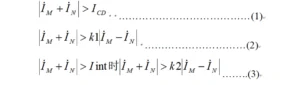
- Equation (2) is the main criterion, where M and N represent the two sides of the circuit.
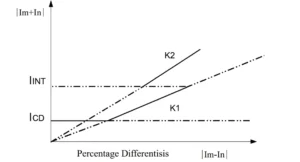
- As an overhead line protection relay and transmission line protection relay, this device defines K1 and K2 as proportional restraint coefficients, set to 0.5 and 0.7 respectively.
ICD is the initial operating current, namely the differential current setting value.
IINT denotes the inflection point current, which is 4 times the rated current.
- This device is equipped with a differential current overload alarm function.
When the differential current exceeds 0.5 times the differential current setting, an alarm will be triggered after a 2-second delay.
- The device supports CT disconnection blocking function.
For phase-based CT disconnection detection, the following two conditions shall be satisfied simultaneously:
- The differential current is greater than 0.5 times the differential current setting;
- No current exists on the local side, while the remote side current is less than 6A.
- The device is provided with second harmonic restraint function.
When the second harmonic component exceeds 20% of the fundamental wave, the differential protection will be blocked.
Outline and Installation Dimensions


FAQ
Q:what is line differential protection relay?
A:The basic principle of line differential protection is to use current transformers in the power system to convert current signals into voltage signals, and then detect faults and provide protection by comparing the magnitude of the current at both ends of the line or on both sides of the equipment.
When a fault occurs on a line, the current near the fault point changes, causing the magnitude and phase of the currents at both ends of the line to become unequal. The differential current is no longer zero, thereby triggering the protective action.
As relays used for transmission line protection and protective relay price for transmission line are concerned, compared with conventional relay protection, the price of such equipment is slightly higher.
Q:What are the most common types of line protection relays?
A:numerical relay for transmission line protection,combined line differential and distance protection relay,line distance protection relay,and Standard line protection relays.
Q1: ANSI code of line differential protection?
A: ANSI standard code is 87L.
2 reviews for ASL-441XLH line differential protection relay
Related products


High Quality
Stable performance, reliable design, ensuring safe operation for power system protection and grid stability.
Fast Delivery
Timely delivery to support your urgent orders and project schedules efficiently and professionally at any time.
Best Warranty
Professional Warranty: Reliable after-sales support for stable relay protection and long-term customer satisfaction.
xiao zhang –
Line differential protection relay (ANSI 87L) features outstanding anti-CT-saturation performance and high sensitivity for internal short-circuit faults. Real-time bidirectional current data exchange ensures reliable discrimination between in-zone and out-of-zone faults; multiple communication interfaces available for global transmission line projects.
Jack –
Accurate protection settings, clean trip operation — no misoperation or failure to operate.