-
Leon Zhang sales consultant
-
Email: zxl635973785@gmail.com
-
Phone/WhatsApp: +86 13655813266


Bus Differential Protection 87B
Bus Differential Protection Overview
The bus protection with differential relay device is suitable for busbars in conventional substations rated at 110 kV and below regardless of wiring configuration; it supports up to nine connected units including the bus tie, perfectly fitting application scenarios of conventional substations.
Communication Mode:Optional: RS-485, CAN bus, Ethernet, IEC61850,IEC103
In-house Factory & Technical Team, OEM ODM Custom Electrical Equipment
Send your requirements, we will quote for you within 12 hours
Description
Bus Differential Protection Overview
- The bus protection with differential relay device is suitable for busbars in conventional substations rated at 110 kV and below regardless of wiring configuration; it supports up to nine connected units including the bus tie, perfectly fitting application scenarios of conventional substations.
- Busbar protection devices feature multiple protection functions and adopt flexible bus differential protection schemes configurable to match various busbar wiring requirements.
Protection features
- Busbar Differential Protection
- Bus Tie Charging Protection
- Bus Tie Circuit Breaker Failure and Dead Zone Protection
- Circuit Breaker Failure Protection
- CT Broken Line Detection
- PT Fuse Failure Detection
Product Features – Differential Current Protection of Busbar
- The software is designed using modular principles, allowing for flexible configuration of protection functions to meet the needs of different users.
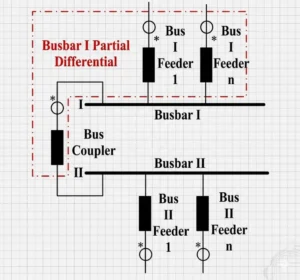
- This differential current protection device adopts the ratio-braking differential protection principle, integrating large-difference and small-difference functions for each busbar section.
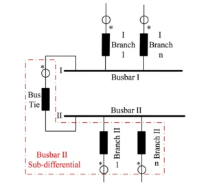
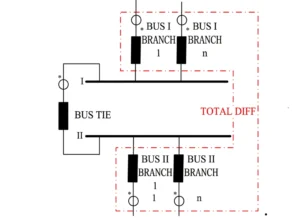
- The large-difference function takes the entire double-busbar system as the protected unit to detect internal busbar faults, while the small-difference functions regard each individual busbar section as the protected unit to accurately locate the faulty busbar section.
- This differential electrical protection device is equipped with 3 Ethernet ports and supports communication with monitoring systems via the IEC 61850-MMS protocol.
- The differential current protection of busbars supports multiple time synchronization methods, including SNTP, Code B and GPS pulse.
- This current differential protection of busbar adopts an instantaneous differential current algorithm, ensuring fast protection response with a total operating time within 25 ms.
- Bus protection with differential relay and bus differential protection systems can automatically adapt to various busbar operating modes.
- During switching operations in double-busbar configurations, no protection deactivation is required. By detecting changes in isolating switch positions, the system automatically identifies the operating mode through software, adjusts the calculation logic for each busbar section’s differential protection, and switches feeder trip commands accordingly.
Busbar Differential Protection Scheme
Protection startup criteria
- This current differential protection relay is equipped with two trip functions to adapt to power systems of different capacities and various fault types: fast trip based on differential current variation and delayed trip based on differential current integration. The fast trip enables rapid and precise fault detection, while the delayed trip guarantees reliable operating sensitivity.
Subfunctions of Differential Protection for 87T Differential Protection Relay
- Section I Busbar Ratio Restrained Minor Differential Protection Function
- Section II Busbar Ratio Restrained Minor Differential Protection Function
- Ratio Restrained Major Differential Protection Function
- CT Broken Line Blocking and Alarm Function
- Composite Voltage Blocking Function
Small-difference differential protection for Section I busbars
Section II Busbar Ratio Differential Protection Function
Ratio-based differential protection function
Bus Differential Protection Settings
| Category | No. | Name | Range | Unit / Definition |
|---|---|---|---|---|
| Differential Protection | 1 | Differential Protection Starting Current Setting | 0.25~100 | A |
| 2 | CT Broken Line Alarm Setting | 0.25~100 | A | |
| 3 | CT Broken Line Blocking Setting | 0.25~100 | A | |
| 4 | Bus Tie & Section Breaker Failure Current Setting | 0.25~100 | A | |
| 5 | Bus Tie & Section Breaker Failure Time Delay | 0~10 | s | |
| Breaker Failure Protection | 6 | Undervoltage Blocking Setting | 0~57.7 | V |
| 7 | Zero-sequence Voltage Blocking Setting | 0~57.7 | V | |
| 8 | Negative-sequence Voltage Blocking Setting | 0~57.7 | V | |
| 9 | Three-phase Failure Phase Current Setting | 0.25~100 | A | |
| 10 | Breaker Failure Zero-sequence Current Setting | 0.25~100 | A | |
| 11 | Breaker Failure Negative-sequence Current Setting | 0.25~100 | A | |
| 12 | Breaker Failure 1st Time Limit | 0~10 | s | |
| 13 | Breaker Failure 2nd Time Limit | 0~10 | s | |
| Optional Function
Bus Tie Charging Overcurrent Protection |
14 | Charging Overcurrent Stage I Current Setting | 0.25~100 | A |
| 15 | Charging Overcurrent Stage I Time Delay | 0.1~10 | s | |
| 16 | Charging Overcurrent Stage II Current Setting | 0.25~100 | A | |
| 17 | Charging Zero-sequence Overcurrent Setting | 0.25~100 | A | |
| 18 | Charging Overcurrent Stage II Time Delay | 0.1~10 | s |
Appearance of a Busbar Differential Protection Device
FAQ
Q:What is the bus differential protection configuration?
A:
The differential scheme for busbar protection adopts phase-separated ratio differential protection as the core configuration of busbar differential protection systems, which includes a large-difference circuit to distinguish in-zone and out-of-zone faults, and a small-difference circuit to identify and select the faulty busbar section.
The system is supplemented by comprehensive auxiliary functions, such as bus tie charging protection, bus tie failure protection, bus tie dead-zone protection, bus tie overcurrent protection, circuit breaker failure protection, composite voltage interlocking, and CT open-circuit interlocking.
For power systems with a rated voltage of 220 kV and above, two independent sets of protection equipment are configured strictly in accordance with the redundancy design principle.
2 reviews for Bus Differential Protection 87B
Related products


High Quality
Stable performance, reliable design, ensuring safe operation for power system protection and grid stability.
Fast Delivery
Timely delivery to support your urgent orders and project schedules efficiently and professionally at any time.
Best Warranty
Professional Warranty: Reliable after-sales support for stable relay protection and long-term customer satisfaction.
xiao zhang –
Dependable bus differential protection (ANSI 87B). Quick fault tripping, strong anti‑CT‑saturation performance, suits various substation busbar configurations for global projects.
Jack –
Fast fault clearing time, enhances overall system stability.