-
Leon Zhang sales consultant
-
Email: zxl635973785@gmail.com
-
Phone/WhatsApp: +86 13655813266


ASL-7615 line distance protection relay
Overview
Distance protection measures the distance (or impedance) between the fault location and the protection installation point. Distance relay protection of transmission lines, also referred to as line protection with distance relays, adopts distance relays as the core protective devices, which determine the operating time of protection based on the measured fault distance.
Function Configuration
21/51/51N/51G/79/27/49/81
Communication Mode:Optional: RS-485, CAN bus, Ethernet, IEC 60870-5-103 (IEC-103)
In-house Factory & Technical Team, OEM ODM Custom Electrical Equipment
Send your requirements, we will quote for you within 12 hours
Description
guide for protective relay applications to transmission lines
- Distance protection measures the distance (or impedance) between the fault location and the protection installation point. Distance relay protection of transmission lines, also referred to as line protection with distance relays, adopts distance relays as the core protective devices, which determine the operating time of protection based on the measured fault distance.
Function Configuration of Line Distance Protection Relay
Main Protection Functions
| No. | Function Name | ANSI Code |
|---|---|---|
| 1 | Three-stage Distance Protection | 21 |
| 2 | Three-stage Phase Overcurrent Protection | 51 |
| 3 | Two-stage Zero-sequence Overcurrent Protection | 51N / 51G |
| 4 | Three-phase Single-shot Auto-reclosing | 79 |
| 5 | Post-closing Phase / Zero-sequence Current Acceleration Protection | 51ACC |
| 6 | Under-frequency Load Shedding Protection | 81U |
| 7 | Under-voltage Load Shedding Protection | 21 / 27 |
| 8 | Overload Alarm | 49 |
| 9 | Zero-sequence Current Alarm | 51N |
| 10 | Ground Fault Alarm | 51G |
| 11 | Frequency Anomaly Alarm | 81 |
| 12 | Spring Uncharged Alarm | — |
| 13 | Control Circuit Break Alarm | — |
| 14 | TWJ Abnormal Alarm | — |
| 15 | PT Broken Line Alarm | 60 |
| 16 | CT Broken Line Alarm | 60 |
| 17 | Fault Waveform Recording | — |
Main Measurement & Control Functions
- 8-channel remote signal binary input acquisition and device remote signal displacement;
- Remote measurement of 14 analog quantities including Ia, Ib, Ic, 3I0, Ua, Ub, Uc, Uab, Ubc, Uca, P, Q, COSφ and F;
- Remote opening and closing control;
- Small current ground fault line selection test trip (auto-reclosing function supported, external zero-sequence current input required);
- Time synchronization.
Principle
- Protection of transmission line with distance relay adopts the working principle of distance protection. Distance protection works by using an impedance relay to measure the impedance between the fault location and the protection installation point, thereby determining the distance to the fault.
- As a core protective relay product for transmission line, it takes the ratio of the busbar voltage at the protection installation point to the line current as the measured impedance, which reflects the impedance between the protection installation point and the fault location.
- For protective relay transmission line application scenarios, the measured impedance is directly proportional to the distance from the fault location to the protection installation point and is largely unaffected by the operating mode; therefore, the range of distance protection remains essentially constant regardless of changes in operating mode.
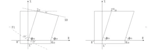
line diagram protective relay descriptions
Transmission Line Protection Distance Relays — Setting List
| No. | Setting Name | Setting Range (IN=1A or 5A) | Unit | Remarks |
|---|---|---|---|---|
| 1 | Variation Starting Current Setting | (0.05 ~ 3)IN | A | |
| 2 | Line Positive Sequence Impedance Setting | (0.05~655)/In | Ω | |
| 3 | Line Positive Sequence Impedance Angle | 30°~89° | — | |
| 4 | Total Line Length | 0~655 | km | |
| 5 | Phase Distance Zone I Setting | (0.05~125)/In | Ω | |
| 6 | Phase Distance Zone II Setting | (0.05~125)/In | Ω | |
| 7 | Phase Distance Zone II Time Delay | 0.01~10 | s | |
| 8 | Phase Distance Zone III Setting | (0.05~125)/In | Ω | |
| 9 | Phase Distance Zone III Time Delay | 0.01~10.00 | s | |
| 10 | Overcurrent Zone I Setting | (0.05 ~ 20)IN | A | |
| 11 | Overcurrent Zone I Time Delay | 0 ~ 10 | s | |
| 12 | Overcurrent Zone II Setting | (0.05 ~ 20)IN | A | |
| 13 | Overcurrent Zone II Time Delay | 0.1 ~ 10 | s | |
| 14 | Overcurrent Zone III Setting | (0.05 ~ 20)IN | A | |
| 15 | Overcurrent Zone III Time Delay | 0.1 ~ 10 | s | |
| 16 | Overcurrent Undervoltage Setting | 10 ~ 100 | V | Line Voltage |
| 17 | Overcurrent Negative Sequence Voltage Setting | 2 ~ 57 | V | U2 |
| 18 | Zero-sequence Overcurrent Zone I Setting | (0.05 ~ 20) | A | |
| 19 | Zero-sequence Overcurrent Zone I Time Delay | 0 ~ 10 | s | |
| 20 | Zero-sequence Overcurrent Zone II Setting | (0.05 ~ 20) | A | |
| 21 | Zero-sequence Overcurrent Zone II Time Delay | 0.1 ~ 10 | s | |
| 22 | Overcurrent Acceleration Setting | (0.05 ~ 20)IN | A | |
| 23 | Overcurrent Acceleration Time Delay | 0.00~ 3 | s | |
| 24 | Zero-sequence Overcurrent Acceleration Setting | (0.05 ~ 20)IN | A | |
| 25 | Zero-sequence Overcurrent Acceleration Time Delay | 0.00~ 3 | s | |
| 26 | PT Broken Line Phase Overcurrent Setting | (0.05 ~ 20)IN | A | |
| 27 | PT Broken Line Phase Overcurrent Time Delay | 0.1 ~ 10 | s | |
| 28 | Overload Setting | (0.05 ~ 20)IN | A | |
| 29 | Overload Time Delay | 1 ~ 3600 | s | |
| 30 | Synchronization Closing Angle | 10°~ 50° | — | |
| 31 | Auto-reclosing Time Delay | 0.1 ~ 10 | s | |
| 32 | High Current Reclosing Block Setting | (0.05 ~ 20)IN | A | |
| 33 | Under-frequency Load Shedding Frequency | 45 ~ 49.5 | Hz | |
| 34 | Under-frequency Load Shedding Time Delay | 0.1 ~ 40 | s | |
| 35 | Under-frequency Slip Block Setting | 0.5 ~ 20 | Hz/s | |
| 36 | Under-frequency Voltage Block Setting | 30 ~ 100 | V | Line Voltage |
| 37 | Under-voltage Load Shedding Voltage Setting | 30 ~ 100 | V | |
| 38 | Under-voltage Load Shedding Time Delay | 0.1 ~ 40 | s | |
| 39 | Voltage Change Rate Block Setting | 10 ~ 200 | V/s | Line Voltage |
| 40 | Power Swing Block Overcurrent | (0.05~20)In | A | |
| 41 | Distance Protection Resistance Setting | (0.05~125)/In | Ω | |
| 42 | Accelerated Distance Zone III Time Delay | 0.0~10 | s |
Outline and Installation Dimensions


FAQ
Q:What is the difference between line differential protection and transmission line distance protection relay?
A:Fiber-optic differential protection is based on real-time comparison of currents at both ends of the line; it has no setting blind zones and is not affected by system operating modes or transition resistances.
Distance protection relies on distance protection relays on transmission lines to measure fault impedance and determine the fault distance; it is set using local electrical quantities and is susceptible to interference from system operating conditions and transition resistances.
Q:How difficult are the experiments for line differential protection and line distance protection, respectively?
When conducting line differential protection relay testingand line distance protection experiments, it is essential to strictly follow the technical manual. In my opinion, the line distance protection experiment is somewhat more challenging.
Q: ANSI standard code for distance protection?
A: Standard ANSI code is 21
3 reviews for ASL-7615 line distance protection relay
Related products


High Quality
Stable performance, reliable design, ensuring safe operation for power system protection and grid stability.
Fast Delivery
Timely delivery to support your urgent orders and project schedules efficiently and professionally at any time.
Best Warranty
Professional Warranty: Reliable after-sales support for stable relay protection and long-term customer satisfaction.
xiao zhang –
This line distance protection relay (ANSI 21) adopts segmental impedance-type distance logic, effectively resisting load swing and fault transition resistance. Equipped with fault location function and optional multi-protocol communication, widely used for overhead transmission and cable line protection in global power grid projects.
Jack –
Communication protocol compatible with mainstream platforms, stable data upload — good product.
Jack –
Solid hardware workmanship, clearly marked terminals, easy installation.