

-
Leon Zhang sales consultant
-
Email: zxl635973785@gmail.com
-
Phone/WhatsApp: +86 13655813266
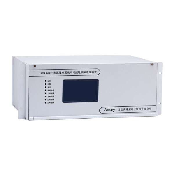
610H Small Current Grounding Line Selection Device
The Small current grounding line selecting device is suitable for identifying single-phase ground faults in power systems with an ungrounded neutral or a neutral grounded through a resistor or an arc-suppression coil.
Communication Mode:Optional:
RS-485, CAN bus, Ethernet, IEC 60870-5-103 (IEC-103)
Send your requirements, we will quote for you within 12 hours
Description
What Is a Small Current Grounding Line Selection Device?
Specifically designed for neutral ungrounded or resonant-grounded systems, the low current grounding line selection device—commonly known as a grounding line selection device—accurately identifies the faulty feeder among multiple outgoing lines when a single-phase-to-ground fault occurs. By overcoming the line-selection challenge posed by weak fault currents and elusive signals, it enables rapid fault isolation, prevents arc-induced fires, minimizes outage scope, and ultimately ensures safe and reliable grid operation.
How Does a Small Current Grounding Line Selection Device Work?
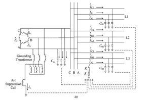
The device continuously monitors zero-sequence signals generated during single-phase-to-ground faults in neutral ungrounded or resonant-grounded systems. By analyzing these signals, it pinpoints the faulted feeder and initiates appropriate protection actions.
Zero-Sequence Current Measurement
The device uses CTs on each outgoing feeder to measure zero-sequence current—the vector sum of three-phase currents. Under fault conditions, the faulted feeder carries the highest zero-sequence current, serving as the primary indicator for line selection.
Zero-Sequence Voltage Detection
VTs on the system bus detect zero-sequence voltage, which rises sharply from near zero when a ground fault occurs. This voltage increase triggers the selection process and provides critical phase reference for fault analysis.
Fault Current and Phase Analysis
The device compares the phase relationship between zero-sequence current and voltage. In ungrounded systems, faulted line currents are in phase opposition to healthy ones; in resonant-grounded systems, additional transient or harmonic analysis is used to overcome compensation effects.
Faulted Line Identification
Using magnitude comparison, phase polarity, and advanced algorithms (e.g., transient analysis, harmonic injection), the device determines which feeder is faulted. Voting and correlation checks ensure high reliability and reject noise-induced errors.
Alarm and Trip Output
Once identified, the device outputs alarms for operator awareness and can issue trip commands to isolate the faulted feeder. Communication via SCADA protocols enables remote monitoring and integration with distribution management systems.
Applications of Small Current Grounding Line Selection Devices
These devices are deployed across medium-voltage networks with ungrounded or resonant-grounded neutrals to enable rapid faulted feeder identification, ensuring service continuity, equipment protection, and operational safety. Key application areas include:
10kV Distribution Systems
The most common application, as 10kV networks typically adopt low-current grounding. With long feeders and numerous branches, the device swiftly isolates faults, preventing escalation and minimizing customer outage minutes.
20kV and 35kV Distribution Networks
Higher capacitance and fault currents demand more sophisticated algorithms. The device reliably pinpoints faults in long-distance or heavily branched feeders, maintaining safety and enabling quick service restoration.
Substations
Installed at busbar or feeder panel level, the device provides clear fault indication for operators, reduces diagnosis time, and integrates with SCADA for centralized monitoring in automated or unmanned substations.
Industrial Power Systems
In petrochemical, steel, mining, and manufacturing plants, the device quickly locates faults amid high noise and switching transients, preventing production stoppages, equipment damage, and arc flash hazards.
Power Plants
Monitoring auxiliary 6kV or 10kV feeders, the device protects generators and station-service transformers by providing early warning and selective tripping, ensuring high plant availability even in EMI-rich environments.
Renewable Energy and Distribution Systems
In solar, wind, and battery storage plants, the device isolates faults in collector networks while keeping healthy feeders online, supporting remote reporting and coordination with grid protection for reliable renewable integration.
How to Select a Small Current Grounding Line Selection Device
| Selection Factor | What to Consider |
|---|---|
| System Voltage | 6kV, 10kV, 20kV, 35kV, etc. |
| Grounding Method | Ungrounded, resonant grounded, high-resistance grounded |
| Number of Feeders | Number of outgoing lines |
| Zero-Sequence CT | CT ratio and measurement range |
| Fault Detection Method | Transient, steady-state, comprehensive criteria |
| Communication | RS485, Ethernet, IEC 61850, GOOSE |
| Output | Alarm, trip, communication |
Small Current Grounding Line Selection Device vs. Ground Fault Relay
| Feature | Grounding Line Selection Device | Ground Fault Relay |
|---|---|---|
| Main Purpose | Identify the faulted feeder | Detect ground fault |
| Fault Line Identification | Yes | Usually limited |
| Zero-Sequence Measurement | Yes | Yes |
| Multiple Feeder Analysis | Yes | Usually no |
| Application | Low-current grounding systems | Ground fault protection |
| Main Output | Fault line indication/alarm/trip | Alarm/trip |
Small Current Grounding Line SelectionFeatures
| Category | Function Item | Core Specification |
|---|---|---|
| Grounding Line Selection Function | Transient Line Selection | Adopts transient route selection method |
| Grounding Line Selection Function | Zero-sequence Directional Line Selection | Adopts zero-sequence overcurrent directional selection method |
| Grounding Line Selection Function | PT Monitoring & Protection | Supports PT de-resonance and PT open-circuit monitoring |
| Grounding Line Selection Function | Reclosing & Acceleration Protection | Equipped with reclosing function and post-reclosing acceleration protection |
| Device Self-Test Function | Hardware Fault Detection | Automatically detects RAM, FLASH, A/D, power loss and other hardware faults |
| Device Self-Test Function | Parameter Validity Check | Automatically verifies setpoints, configuration parameters, coefficients and other settings |
| Communication Function | Communication Interface Support | Supports RS-485, RS-232, Ethernet and IEC 61850 communication modes (specify when ordering) |
| Communication Function | Real-time Data Upload | Can upload busbar voltage, current, grounding information, harmonic data and other real-time operating data |
| Communication Function | Remote Control & Command Reception | Can receive remote control, system synchronization and other control commands from the upper-level system |
| Panel & Operation Function | Human-machine Interface | Equipped with Chinese character LCD display, status indicator lights and keypad for easy monitoring and operation |
| Time Synchronization Function | Network Time Sync | Supports network-based time synchronization via communication channels |
| Time Synchronization Function | IRIG-B Code Sync | Supports IRIG-B code time synchronization |
Rated Electrical Parameters
| Category | Parameter Name | Specification Requirements |
|---|---|---|
| Power Supply Specifications | Rated Operating Voltage | AC/DC 220 V |
| Power Supply Specifications | Permissible Voltage Deviation | -20% ~ +15% |
| Power Supply Specifications | Ripple Factor | ≤5% |
| AC Circuit Specifications | AC Rated Current In | 1 A/5 A |
| AC Circuit Specifications | AC Rated Voltage Un | 100 V |
| AC Circuit Specifications | Rated Operating Frequency | 50 Hz |
| Power Consumption Specifications | DC Power Circuit Power Consumption | ≤25 VA during normal operation; ≤30 VA when the device is activated |
| Power Consumption Specifications | AC Voltage Circuit Power Consumption | ≤1 VA per phase at rated voltage of 100 V |
| Power Consumption Specifications | AC Current Circuit Power Consumption | ≤0.5 VA per phase at rated current of 1 A; ≤1 VA per phase at rated current of 5 A |
Small current grounding line selecting device Mechanical Installation Dimensions Drawing
- Dimensions: Width × Height × Depth = 484 × 177 × 285 (mm)
- Mounting hole dimensions: 445 × 177 (with 4 mounting holes, each 6.5 mm in diameter)
Small Current Grounding Line Selection Device Fixed-Price Order
| No. | Display Name | Range | Step | Remark |
|---|---|---|---|---|
| 1 | Bus Setting | Bus I setting
Bus II / Bus III / Bus IV are consistent with Bus I |
||
| 1.1 | Name | M001~M004 | 1 | |
| 1.2 | PT Ratio | 1-1000 | — | |
| 1.3 | PT Disconnection | Enable / Disable | — | |
| 1.4 | Outlet Quantity | — | — | |
| 1.5 | Earth Fault Trip | Enable / Disable | — | Enable for trip, Disable for alarm |
| 1.6 | Earth Fault Time Delay | 0.1S | 0.1S | |
| 1.7 | Post Acceleration | Enable / Disable | — | Need to set acceleration time if enabled |
| 1.8 | Earth Fault Voltage | 5.0~100.0V | 0.1V | |
| 1.9 | Rotation Control | Enable / Disable | — | |
| 1.10 | Voltage Threshold | 0.1~100.0V | 0.1V | |
| 1.11 | Voltage Dead Zone | 0.1~100.0V | 0.1V | |
| 1.12 | Rotation Mode | Auto / Fixed | — | Auto rotation mode / Fixed rotation mode |
| 1.13 | Rotation Time Delay | 0.1S | 0.1S | |
| 1.14 | PT Blocking Earth Protection | Enable / Disable | — | Block earth protection when PT disconnection occurs |
| 1.15 | Rotation Voltage | 5.0~100.0V | 0.1V | |
| 1.16 | Corresponding Bus Number | 1-4 | — | |
| 1.17 | Permanent Fault Time Delay | 0~100.0S | 0.1S | |
| 1.18 | Spare | Enable / Disable | — | |
| 1.19 | Current Threshold | 5~100mA | 1mA | |
| 1.20 | Spare | Enable / Disable | — | |
| 1.21 | Current Dead Zone | 5~100mA | 1mA | |
| 1.22 | Spare | Enable / Disable | — | |
| 1.23 | Spare | Enable / Disable | — | |
| 2 | Feeder Setting | Feeder No.01
Other feeders follow the same setting |
||
| 2.1 | Name | Line I B001 | — | |
| 2.2 | Line Type | Overhead / Cable / Station Internal | — | |
| 2.3 | Line Trip Output No. | — | — | |
| 2.4 | CT Ratio | 1~1000 | — | |
| 2.5 | CT Polarity | Positive / Reverse | — | |
| 2.6 | Transient Earth Fault Setting | 5~100mA | 1mA | |
| 2.7 | Earth Delay High Byte | 0~100.0S | 0.1S | |
| 2.8 | Line Earth Fault Trip | Enable / Disable | — | Trip when enabled, alarm when disabled |
| 2.9 | Earth Fault Current | 5~100mA | 1mA | |
| 2.10 | Spare | — | — | |
| 2.11 | Earth Delay Low Byte | 0~100.0S | 0.1S | |
| 2.12 | Rotation Control | Enable / Disable | — | Participate in rotation if enabled |
| 2.13 | Rotation Sequence | 1-4 | — | |
| 2.14 | Line Closing Output No. | — | — | |
| 2.15 | Auto-reclosing Enable | 0 / 1 | — | |
| 2.16 | Protection Trigger Reclosing | 0 / 1 | — | |
| 2.17 | Reclosing Time Delay | 0~100.0S | 0.1S | |
| 3 | Spare Setting | — | — | |
| 4 | Resonance Threshold Setting | |||
| 4.1 | Spare | 5.0~100.0V | 0.1V | |
| 4.2 | Spare | 5.0~100.0V | 0.1V | |
| 4.3 | 17Hz Resonance Threshold | 5.0~100.0V | 0.1V | |
| 4.4 | 25Hz Resonance Threshold | 5.0~100.0V | 0.1V | |
| 4.5 | 50Hz Resonance Threshold | 5.0~100.0V | 0.1V | |
| 4.6 | 150Hz Resonance Threshold | 5.0~100.0V | 0.1V | |
| 4.7 | 250Hz Resonance Threshold | 5.0~100.0V | 0.1V | |
| 4.8 | Overvoltage Threshold | 5.0~100.0V | 0.1V | |
| 5 | Binary Input Setting | |||
| 5.1 | Debounce Time Delay | 10ms~9999ms | — | Factory default: 20ms |
| Remote Signal Polarity 1~48 | 0 or 1 | — | ||
| 6 | LCD Setting | |||
| 6.1 | Fault Lamp Reset Mode | Auto / Manual | — | |
| 6.2 | Fault Lamp Return Time | 0~120S | 1s |
FAQ
1. What is a small current grounding line selection device?
A small current grounding line selection device is a protection and fault-detection device used to identify the faulted feeder when a single-phase-to-ground fault occurs in a low-current grounding system. It analyzes electrical signals such as zero-sequence current and voltage to determine which outgoing line is experiencing the grounding fault.
2. What is a small current grounding system?
A small current grounding system is a power distribution system in which the grounding fault current is relatively low. Common grounding arrangements include ungrounded, resonant-grounded, and other low-current grounding configurations. Because the fault current can be difficult to distinguish from normal system currents, dedicated fault line selection equipment may be required.
3. What does a grounding line selection device detect?
The device is primarily used to detect and identify the feeder associated with a single-phase grounding fault. Depending on the system configuration and device design, it can analyze zero-sequence current, zero-sequence voltage, transient components, phase relationships, and other electrical characteristics.
4. How does a small current grounding line selection device work?
The device collects grounding-related electrical signals from multiple outgoing feeders and analyzes their characteristics. By comparing zero-sequence quantities and other fault indicators, the protection algorithm determines the most likely faulted feeder and provides an alarm, indication, communication signal, or trip output according to the system configuration.
5. Can it identify the faulted feeder in a 10kV distribution system?
Yes. Small current grounding line selection devices are commonly applied to medium-voltage distribution systems where single-phase grounding faults may occur with relatively small fault currents. The actual applicable voltage level, feeder configuration, CT arrangement, and grounding method should be confirmed according to the project requirements.
6. What is the difference between ground fault protection and grounding line selection?
Ground fault protection is primarily intended to detect an abnormal ground-fault condition and initiate an alarm or trip. Grounding line selection goes one step further by identifying which outgoing feeder is most likely associated with the grounding fault. Therefore, a grounding line selection device can be particularly useful in systems with multiple outgoing feeders.
7. What signals are required for grounding line selection?
The required signals depend on the protection method and system configuration. Typical inputs may include zero-sequence current, zero-sequence voltage, phase voltage, and other electrical quantities used by the fault-selection algorithm. CT and PT/VT arrangements should be selected according to the specific grounding system.
8. Can the device be used for intermittent or transient grounding faults?
The capability depends on the protection algorithm and product configuration. Some grounding line selection systems use transient fault characteristics in addition to steady-state electrical quantities, which can improve fault identification when the grounding current is small or unstable.
9. What is the difference between a small current grounding line selection device and a ground fault relay?
A ground fault relay generally focuses on detecting ground-fault current or voltage and providing protection output. A small current grounding line selection device is designed specifically to determine the faulted feeder in a low-current grounding network. In multi-feeder distribution systems, line-selection functionality can provide more detailed fault information than a basic ground-fault detection function.
10. Where are small current grounding line selection devices used?
Typical applications include medium-voltage distribution networks, substations, industrial power systems, power plants, and other electrical systems using low-current grounding methods. They are especially useful where operators need to quickly identify the affected feeder without manually checking multiple outgoing lines.
11. How do I select the right grounding line selection device?
Selection should consider the system voltage, grounding method, number of outgoing feeders, CT/PT configuration, fault-detection method, required communication interfaces, installation method, and required alarm or trip outputs. For a project-specific selection, the system single-line diagram and basic electrical parameters should be reviewed before choosing the device.
12. Can the grounding line selection device communicate with a SCADA system?
Depending on the product configuration, communication interfaces can be provided for integration with substation automation or SCADA systems. The available communication protocol, physical interface, data points, and network architecture should be confirmed according to the selected model.
13. What information should I provide when requesting a quotation?
For accurate product selection, it is recommended to provide the system voltage, grounding method, number of outgoing feeders, CT/PT information, protection requirements, communication requirements, installation conditions, and the required quantity. A single-line diagram is also helpful for engineering evaluation.
14. Can you provide technical support for grounding line selection projects?
Yes. Project-specific technical support can include product selection, configuration recommendations, application guidance, and assistance with the required electrical parameters. Customers can provide their system information or single-line diagram for a more accurate recommendation.
2 reviews for 610H Small Current Grounding Line Selection Device
Related products
High Quality
Stable performance, reliable design, ensuring safe operation for power system protection and grid stability.
Fast Delivery
Timely delivery to support your urgent orders and project schedules efficiently and professionally at any time.
Best Warranty
Professional Warranty: Reliable after-sales support for stable relay protection and long-term customer satisfaction.
xiao zhang –
This feeder selector accurately picks faulty feeder under small-current earthing system. High anti-interference, adjustable sensitivity and standard communication, widely used in 6~35kV neutral ungrounded distribution substations.
Jack –
Compact and lightweight — shipping and handling are hassle-free.