
-
Leon Zhang Sales Manager
-
Email: sale@relayprotect.com
-
Phone/WhatsApp: +86 13655813266
Earth Fault Relay: Protection, Applications, Settings and Troubleshooting
What is an earth fault relay and how does it work?
An earth fault relay is a protective device that measures residual current (3I0) or zero-sequence voltage (3U0) and trips the circuit breaker when a phase-to-earth current exceeds the set threshold. It covers the one fault path that phase overcurrent elements handle poorly, where a live conductor reaches earth through damaged insulation or moisture. Current-based detection is used on solidly or low-resistance grounded systems; voltage-based detection is used on unearthed or arc-suppression-coil networks. Pickup typically sits at 10 to 40 percent of rated current, above steady-state unbalance and below the lowest fault current the system can produce, with grading margins of 0.3 to 0.5 seconds between successive devices. Sensitive earth fault elements reach down to 50 milliamps on high-impedance systems. The measuring requirements are set in IEC 60255-151:2009 for the 50N and 51N elements, device numbers come from IEEE C37.2-2022, and generator stator earth fault practice follows IEEE C37.102-2023. Relay hardware is judged to IEC 60255-1:2022. Setting review and quotation within 12 hours, MOQ 1, 7-15 working days.
Earth fault relay is a protective device that measures residual current (3I₀) or zero-sequence voltage (3U₀) and trips the circuit breaker when a phase-to-earth fault exceeds the set threshold. It covers the one fault path that phase overcurrent elements handle poorly, where a live conductor reaches earth through damaged insulation or moisture.
Earth fault protection draws on two standards families. IEC 60255-151:2009 fixes the measuring requirements behind the 50N and 51N elements, IEEE C37.2-2022 assigns the device numbers, and IEEE C37.102-2023 covers generator stator earth fault schemes. Common hardware requirements sit in IEC 60255-1:2022. The same event is named an earth fault under IEC and a ground fault under ANSI and the NEC.
These relays sit wherever a live conductor can reach earth. Typical sites include utility substations, industrial plants and solar power stations. Where an earth fault can escalate into an arc, arc flash protection adds a second layer of defence.
Three settings decide whether the scheme works. Pickup sits at 10% to 40% of rated current, above steady-state unbalance and below the lowest fault current the system can produce. Grading margins between successive devices run 0.3 s to 0.5 s. On unearthed or high-impedance systems, sensitive earth fault detection reaches down to 50 mA. Put together, the earth fault relay setting is a pickup percentage, a grading margin in seconds and, on high-impedance systems, a sensitivity threshold in milliamps.
Written by Leon Zhang, Protection Application Engineer · Technical review by the relayprotect.com engineering team · Last reviewed October 2026
Earth Fault Relay at a Glance
- Detects phase-to-earth faults from residual current (3I₀) or zero-sequence voltage (3U₀).
- Device numbers: 50N and 51N for overcurrent earth faults, 67N for directional, 64REF for restricted, 64G for generator stator.
- Typical pickup: 10% to 40% of rated current; sensitive schemes reach 50 mA.
- Time grading: 0.3 s to 0.5 s between successive devices.
- Standard basis: IEC 60255-151:2009, IEC 60255-1:2022, IEEE C37.2-2022 and IEEE C37.102-2023.
- Main risk: nuisance trips from reversed CT polarity, pickup set too low, or motor starting inrush.
- An earth fault protection relay is chosen by the grounding method and the available fault current, not by the relay family alone.
- Order inputs: six specification items decide the model. See the specify list and the lead-time table.
Earth Fault Relay Basics
In a healthy three-phase circuit the three phase currents are nearly balanced, so any current that returns through earth instead of the neutral stands out. An earth fault relay is the device that watches this imbalance and acts on it, whether the target is an alarm or a trip.
It detects single-phase-to-earth faults and insulation degradation by measuring zero-sequence current (3I₀) or zero-sequence voltage (3U₀), depending on the system grounding method: current-based in solidly or low-resistance grounded systems, and voltage-based in unearthed or arc-suppression-coil-grounded systems.
Selecting a relay for a live project?
Send the system voltage, CT ratio and tripping scheme. Our engineers confirm the model and reply within 12 hours.
Upon pickup, it issues an alarm, initiates a time delay, and trips the circuit breaker if the fault persists, while recording fault data for analysis. It is widely applied in protection for feeders, motors, transformers, generators, and distribution lines, especially in medium and low voltage systems with unearthed, arc-suppression-coil-grounded, or low-resistance-grounded neutrals.
How Earth Fault Protection Works
Earth fault protection relay monitors residual current via current transformers. Under normal operating conditions, the vector sum of three-phase currents equals zero, with no residual current flowing through the relay.
Working Principle: Residual Current Method
Normal operating condition
In normal operation, the three-phase currents are balanced, and their vector sum equals zero. No residual current or zero-sequence voltage is present. The relay remains inactive and continuously monitors the system for any abnormality.
Normal condition: Ia + Ib + Ic = 0.
Earth fault condition
When a phase conductor comes into contact with earth, the system symmetry is broken. An unbalanced current flows to earth, creating a residual current (3I₀) or zero-sequence voltage (3U₀), indicating the presence of a fault.
Residual current detection
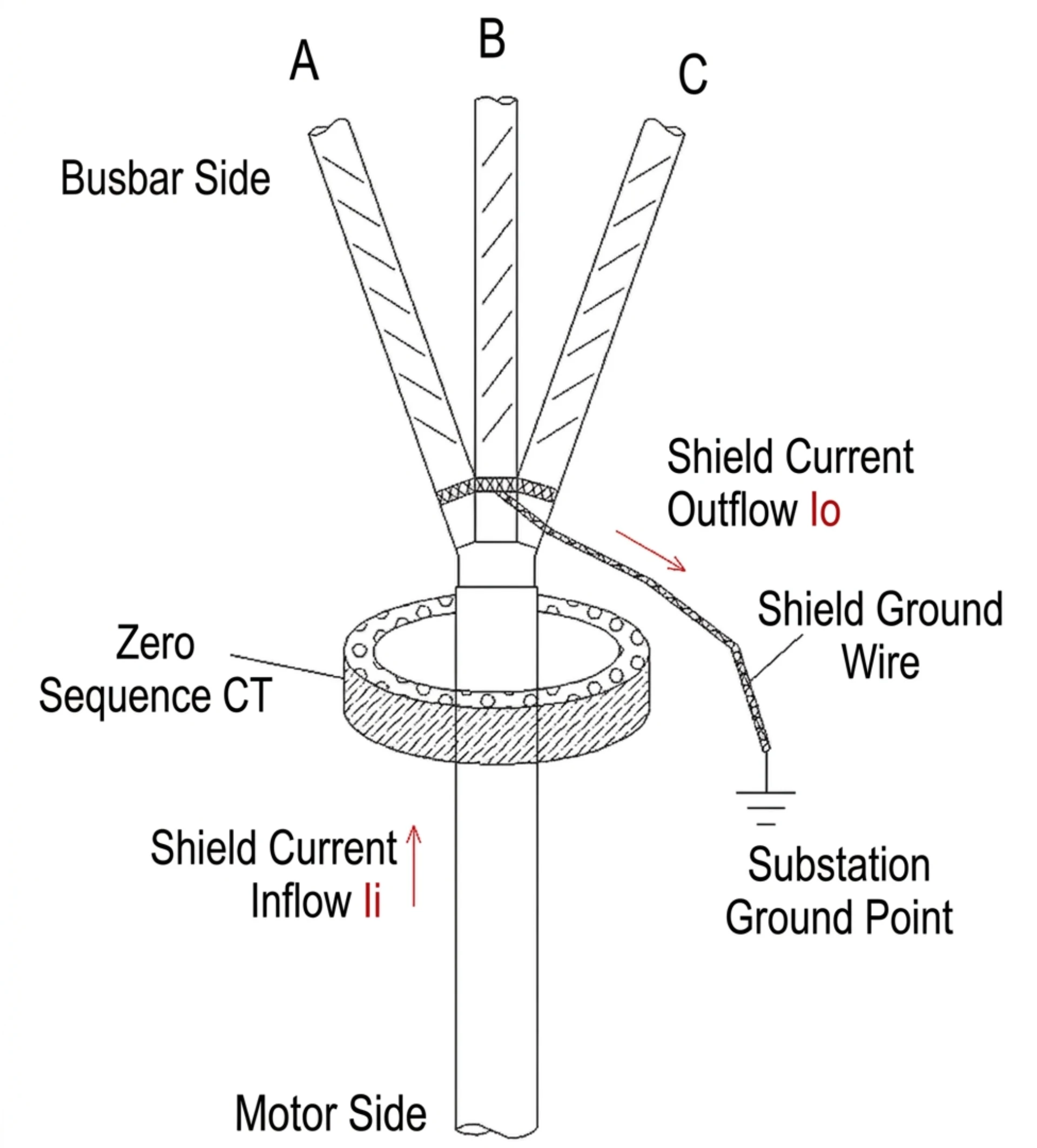
The relay measures residual current using the vector sum of the three-phase currents (Ia + Ib + Ic) via a core-balance current transformer, or measures zero-sequence voltage from the open-delta winding of a voltage transformer. These signals serve as the input to the relay.
Earth fault occurs: Ia + Ib + Ic ≠ 0 → residual current generated.
Relay pickup and trip
Once the measured residual current or voltage exceeds the preset threshold, the relay picks up. It immediately issues an alarm and starts a time delay. If the fault persists beyond the delay setting, the relay outputs a trip command to the circuit breaker.
Circuit breaker operation
Upon receiving the trip command, the circuit breaker opens its contacts, isolating the faulty circuit from the system. This clears the fault and protects downstream equipment. The breaker status can be monitored via auxiliary contacts.

Circuit Diagram and CT Connection
Proper earth fault relay connection is essential to ensure correct fault detection and reliable operation. Two wiring habits decide most site problems: core-balance CTs need the cable sheath earth returned through the window, and residual-connected phase CTs need polarity verified before energization. Both are covered in the test table below.
Types of Earth Fault Protection
50N/51N Overcurrent Earth Fault Element
Detects earth faults by measuring residual current. 50N provides instantaneous tripping for severe faults, while 51N offers time-delayed tripping with inverse-time characteristics for coordination with downstream protection. Suitable for general earth fault protection in feeders and distribution networks. Both sets sit in one device on a numerical platform, and the numerical overcurrent protection relay page lists the element list and measurement inputs.
Sensitive Earth Fault (SEF)
Designed to detect very low earth fault currents, down to a few milliamps, typically using a core-balance CT for high sensitivity. It suits high-impedance grounding systems where fault currents are minimal, giving early warning of insulation degradation before major faults develop.
Directional Earth Fault (67N)
Determines the fault direction by comparing the phase angle between residual current and residual voltage. Only operates when the fault is in the forward direction. Essential for ring main networks and parallel feeders where fault current can flow in both directions, enabling selective fault isolation.
Restricted Earth Fault (64REF)
Protects a specific zone within transformer windings by comparing currents at both ends of the protected zone. Under normal or external fault conditions, currents balance; internal earth faults create a differential current that trips the breaker. Provides high-speed, highly sensitive protection for transformer internal winding earth faults.
Stator Earth Fault (64G)
Built for generator stator winding earth fault protection. Typically installed at the neutral side of the generator, it measures the current flowing through the neutral grounding connection. Detects stator winding insulation failures and trips to prevent severe generator damage. Often used in conjunction with 100% stator earth fault protection schemes for complete coverage.
Function Summary by ANSI Code
| ANSI code | Name | What it does |
|---|---|---|
| 50N | Instantaneous earth overcurrent (N = neutral/earth) | No intentional delay for severe earth faults |
| 51N | Definite-time / inverse-time earth overcurrent | Time-delayed coordination for general earth faults |
| SEF | Sensitive earth fault | Detects mA-level earth fault currents on high-impedance grounded systems |
| 67N | Directional earth fault | Discriminates fault direction on ring mains and parallel feeders |
| 64REF | Restricted earth fault | Transformer winding zone protection against internal earth faults |
| 64G | Stator earth fault | Generator stator winding earth fault detection at the neutral |
Earth Fault Protection Settings: Pickup and Time Delay
Earth Fault Pickup Setting
The pickup setting defines the minimum residual current level that will trigger the relay. It must be set above the maximum expected unbalance current during normal operation to avoid nuisance tripping, while remaining low enough to detect genuine earth faults. Typical settings range from 10% to 40% of the rated current, depending on system grounding and load characteristics.
Time Delay Setting
The time delay setting determines how long the relay waits after pickup before issuing a trip command. This allows downstream protection devices to operate first for faults closer to the load, achieving selective coordination. Delay characteristics can be definite-time (fixed delay) or inverse-time (delay inversely proportional to fault current magnitude).
50N/51N Setting
50N setting defines the instantaneous pickup threshold for high-magnitude earth faults, with no intentional time delay, typically set above the maximum through-fault current to avoid unwanted operation. 51N setting defines the time-current curve for delayed earth fault protection, coordinated with downstream devices. The 51N curve selection (IEC standard inverse, very inverse or extremely inverse) depends on the system requirements and coordination study.
Sensitive Earth Fault Setting
SEF settings are designed for detecting very low earth fault currents in high-impedance grounded or unearthed systems. The pickup value is typically set in the milliamp range (50 mA to 5 A) using a core-balance CT. Time delay is often set longer than standard overcurrent protection to ride through transient disturbances and remain stable.
Directional Earth Fault 67N Setting
67N setting involves configuring both the pickup threshold and the directional characteristic. The relay must be set with a reference polarizing voltage (3U₀) and a characteristic angle (RCA) to define the forward and reverse zones. Proper setting ensures the relay operates only for faults in the forward direction and remains stable for reverse faults or load unbalance.
CT Ratio and Relay Setting
The CT ratio directly affects the relay setting calculations. The relay pickup value in primary amperes must be converted to secondary amperes using the CT ratio (400/5 A, for example). The relay settings are entered in secondary values. Core-balance CT construction and accuracy classes follow IEC 61869-2:2012+AMD1:2017. Proper CT sizing is critical: too small a CT may saturate during high faults, while too large a CT reduces sensitivity for low-level faults.
Coordination and Grading
Coordination ensures that the relay closest to the fault operates first, isolating the minimum section of the network. This is achieved by grading pickup currents and time delays between upstream and downstream relays. The coordination study involves plotting time-current curves (TCC) and ensuring margins between successive devices, typically 0.3 to 0.5 seconds, to maintain selectivity.
Worked Setting Example
For an 11 kV feeder with 400/5 A CTs and 100 A maximum load: set the earth fault pickup at 20% of rated CT primary current = 80 A primary (1 A secondary). Set 51N using the IEC standard inverse curve with a time dial of 0.1 to achieve a 0.4 s coordination margin with the downstream relay. Set 50N instantaneous at 400 A primary (5 A secondary).
The example verifies sensitivity and coordination through TCC plotting and fault current calculations from IEC 60909-0.
How to Test Earth Fault Protection
Settings that look right on paper still have to survive a secondary injection set. The eight checks below run in commissioning order; each one catches a different wiring or setting mistake.
| Test item | What to verify |
|---|---|
| Visual inspection | Relay appearance, terminal tightness, CT/VT wiring against the approved diagram; nameplate ratings match the specification before further testing. |
| CT polarity check | Primary current P1→P2 must produce secondary current S1→S2 through the relay. Verify all phase CTs and the zero-sequence CT; correct reversed connections before energization. |
| Pickup current test | Inject and increase current until pickup; measured value within ±5% of setting, each phase and earth input tested separately. |
| Definite-time test | Trip at the fixed delay; tolerance ≤ ±50 ms or ±5% of setting. |
| Inverse-time test | Inject at 2×, 5× and 10× pickup and measure trip times against the selected curve (e.g. IEC standard inverse). |
| Trip output test | Confirm the trip contact energizes the breaker trip coil and reports to SCADA: the whole trip path, not just the relay LED. |
| Secondary injection test | End-to-end verification of pickup, delays, directional characteristics and outputs against the setting sheets; the standard commissioning method. |
| 67N directional test | Inject current and voltage with adjustable phase angle; confirm forward tripping and reverse blocking, and verify the RCA setting. |

Earth Fault vs Phase Overcurrent (50N/51N vs 50/51)
| Comparison point | Overcurrent relay (50/51) | Earth fault element (50N/51N) |
|---|---|---|
| Monitored current | Three-phase line current | Residual / zero-sequence earth current |
| Protected faults | Phase-phase short circuit, overload, severe high-current earth faults | Phase-earth leakage, insulation breakdown, all ground faults (no phase-phase protection) |
| Sensitivity | Low (high pickup setting) | High (detects small earth leakage) |
| Typical setting | 125%–200% of full load current | 5%–30% of full load current |
| CT connection | Individual CT per phase | Residual summation or zero-sequence CT (ZCT) |
| Core function | Protect equipment from overload and phase faults | Protect system and personnel from earth leakage faults |
When an Earth Fault Relay Is Not the Answer
An earth fault relay protects circuits and equipment. Four boundaries mark the jobs it was never built for, and each one has a dedicated device instead.
- Personnel shock protection: a 30 mA RCD or RCBO protects people, because an industrial element set at 10% of rated current cannot see a leakage that small.
- Feeder selection on ungrounded or Petersen-coil buses: every feeder carries the same small capacitive current, so a plain SEF cannot name the faulted one; a line-selection device or a 67N comparison is required.
- Phase-phase and three-phase faults: the earth element sees none of them; phase 50/51 elements and transformer or motor differential schemes carry that duty.
- DC networks: PV strings and DC auxiliary systems produce no AC residual, so an insulation monitoring device or DC RCM does the watching instead.
What to Specify Before Requesting an Earth Fault Relay Quote
A quotation is only as accurate as the inputs behind it. Send the six items below with the enquiry and the reply comes back with a model number, not with three more questions; most of the values are already written on your single-line diagram.
| # | Specify | Example answer |
|---|---|---|
| 1 | System voltage and neutral earthing | 11 kV resistance-grounded, 400 V TN, unearthed 33 kV; this decides 50N/51N vs SEF vs 67N |
| 2 | CT arrangement | Core-balance (zero-sequence) CT with window diameter and ratio, or residual connection from three phase CTs, e.g. 400/5 A |
| 3 | Pickup range | 10% to 40% of rated current, or mA-level SEF |
| 4 | Output configuration | Number of changeover trip contacts, alarm contacts, trip-circuit supervision |
| 5 | Auxiliary supply | 110/220 V DC station battery, 48 V DC, or 230 V AC panel supply |
| 6 | Communication | RS-485 Modbus, IEC 61850, IEC 60870-5-103/104, DNP3, or none |

What Causes Earth Faults?
Five failure families account for most site events, and each leaves a different signature in the event record. The record rarely lies. The record rarely lies.

Cable insulation deterioration
Thermal aging, repeated overload cycling and partial discharge thin the insulation until leakage current starts to flow. Cables older than about 15 years in hot switchrooms are the classic case, and the event log usually shows a slow upward drift in standing leakage before the first trip.
Moisture and water ingress
Water enters through cable terminations, kiosk door gaskets and flooded duct banks. Seasonal outdoor installations such as solar farms, wind collector platforms and coastal substations see the pattern every wet season. The trips often cluster after the first heavy rain.
Aging electrical equipment
Switchgear busbar insulation, motor winding varnish and transformer bushings all lose margin with age. Unlike cable faults, equipment aging shows up first on one specific circuit, which is where the residual current trend points.
Mechanical damage
Excavation strikes, rodent bites and vibration damage deliver abrupt faults with no warning trend. Protection here is about clearing speed, because the damage is already done when the relay picks up.
Incorrect wiring
Reversed CT polarity, neutral-earth misconnection and crossed metering wiring produce false residuals and nuisance trips with no real fault present. The fix is inspection against the approved diagram and the polarity check in the test table, not a higher pickup setting.
Ground Fault Relay Applications
Earth Fault Protection for Transformers
64REF restricted earth fault protection is used to detect internal winding faults, with neutral-side 51N overcurrent earth fault as backup. The relay is connected to the neutral CT. Upon an internal earth fault it rapidly trips circuit breakers on both HV and LV sides to minimize winding damage and fire risk.
Earth Fault Protection for Generators
64G stator earth fault protection is installed at the generator neutral point, providing high-sensitivity detection of stator winding earth faults. It is often combined with third-harmonic or neutral voltage schemes to achieve 100% winding coverage, preventing small faults from escalating and causing core damage.
Earth Fault Protection for Motors
50N/51N overcurrent earth fault protection is typically used, with leakage detection via core-balance CT or residual connection from three-phase CTs. Settings must consider motor starting current to avoid nuisance tripping. SEF may be applied in high-resistance or unearthed systems for reliable detection of low-magnitude fault currents.
Earth Fault Protection for Feeders
51N overcurrent earth fault protection is mainly used, utilizing residual current from three-phase CTs with delayed inverse-time coordination. For ring main or complex systems, 67N directional earth fault protection discriminates fault direction and achieves selective tripping, ensuring only the faulty section is isolated. The grading against the upstream incomer is worked through in feeder protection in distribution networks.
Earth Fault Protection for Solar Plants
On the AC side, 50N/51N protection is applied at the inverter output or transformer LV side. On the DC side, dedicated RCM monitors leakage between arrays and earth. 67N directional protection may be used in MV collection systems. In unearthed or high-resistance grounded configurations, SEF is commonly used for early insulation degradation warning.
Selection Criteria for Earth Fault Protection
System voltage
The protection type is determined by system voltage:
- LV systems: standard 50N/51N overcurrent earth fault element for general distribution, SEF for equipment with high insulation requirements.
- MV systems: sensitive earth fault element (SEF) plus 67N directional protection for ring networks and renewable collection lines.
- HV systems: dedicated directional earth protection matched with the substation primary equipment.
Grounding method
Four neutral earthing configurations cover almost every installation, and the element choice follows directly from the fault current each one allows.
Solidly grounded system
Standard 50N/51N overcurrent earth fault elements are the primary choice. High earth-fault current ensures stable and dependable fault detection.
Resistance grounded system
A combination of 51N plus SEF detects both heavy short-circuit earth faults and minor leakage faults.
Petersen coil (arc suppression coil) grounded system
SEF high-sensitivity detection is essential, because residual fault current stays extremely low; a line-selection device identifies which feeder carries it.
Ungrounded system
SEF paired with a 67N directional element identifies faint insulation degradation and subtle earth faults, and 67N keeps healthy feeders from tripping on shared capacitive current.
Earthing Scheme Summary
| Neutral arrangement | Earth fault current level | First-choice element | Design note |
|---|---|---|---|
| Solidly grounded | Hundreds of A to kA | 50N/51N | Highest sensitivity margin; watch for inrush on motor feeders |
| Resistance grounded | Tens to hundreds of A | 51N + SEF | SEF catches the low-resistor limit cases 51N misses |
| Petersen coil grounded | A few A residual | SEF + line selection | Fault self-extinguishes; select the feeder, do not trip blindly |
| Ungrounded | Capacitive charging current only | SEF + 67N | Directional logic prevents healthy-feeders tripping on shared charging current |
Communication requirements
Modern projects support multiple mainstream communication protocols for earth fault relays:
- Modbus RTU
- Modbus TCP
- IEC 61850
- IEC 60870-5-104 (IEC 104)
- DNP3
Earth fault relays equipped with these interfaces upload fault records, measured values, setting parameters and relay status to SCADA or a central control system.
Integration with SCADA
Remote monitoring capability has become a key concern for most customers. Protection relays upload real-time operating data, fault alerts and protection parameter values to SCADA systems via standard communication protocols, enabling centralized remote supervision and fault diagnosis from control rooms. The data path is described in the SCADA systems.
Models, Lead Time and What Ships with the Relay
Two catalogue positions cover most enquiries. The ASP-523H carries the 51N zero-sequence element for 400 V TN distribution systems, with phase and earth protection in one housing. On unearthed or Petersen-coil MV busbars where several feeders share the same charging current, the 610H line-selection device identifies the faulted feeder instead of tripping the whole bus. Price depends on rating, output count and communication options and is quoted per enquiry rather than listed.
| Model | ANSI | Typical service | Communication options | Lead time | MOQ |
|---|---|---|---|---|---|
| ASP-523H | 51N | 400 V TN feeders, phase-to-ground short circuit | RS-485, CAN, Ethernet, IEC 103, IEC 61850 | 3–4 weeks ex-works | 1 pc |
| 610H | Line selection | 10–35 kV unearthed / arc-suppression-coil buses | RS-485, CAN, Ethernet, IEC 103 | 3–4 weeks ex-works | 1 pc |
Every order ships with a project pack: datasheet, outline and wiring diagram, setting guide, routine test report, FAT procedure and O&M manual. It is the set the reviewer asks for at submittal. Editable formats are available on request for design consultants.
If you already hold a relay list or BOQ, send it over; a priced BOM with model mapping, per-item lead time and any specification gaps comes back within 48 hours. Enquiries with the six specify items above are quoted within 24 hours.
Modern Features of Digital Protection Relays
| Feature | What it does |
|---|---|
| Self-diagnostics | Real-time device health monitoring |
| Event recording | Full event log for fault and abnormal operation history |
| Fault waveform capture | High-resolution oscillography of fault records |
| Multiple protection functions | Built-in ANSI elements: 50/51 phase overcurrent, 50N/51N neutral earth fault, 67N directional neutral, 49 thermal overload, 46 negative sequence |
| IEC 61850 communication | Fully compliant for digital substation applications |
| Cybersecurity | IEC 62351 and NERC CIP alignment |
Conclusion
Proper selection of an earth fault relay protects equipment, improves system reliability, minimizes downtime, and fulfills the requirements of modern smart grid and renewable energy projects. For projects requiring long-term stable operation and remote monitoring, digital relays with multi-protocol communication, IEC 61850 compatibility, fault recording and sensitive earth detection are the sound choice.
If you are holding a single-line diagram right now, the fastest next step is the six-item specify list above. Send it with your system voltage and CT arrangement, and the reply includes a model, the project pack contents and a firm lead time instead of a brochure.
FAQ
Quick answers to the questions that come up most often during earth fault relay troubleshooting, testing and ordering.
1. What is an earth fault relay?
A protective device that detects earth faults by measuring residual current or zero-sequence voltage, and issues an alarm or trip command to isolate the faulty circuit.
2. Which ANSI codes apply to earth fault protection?
There is no single code. Common codes include 50N (instantaneous), 51N (time-delayed), 67N (directional), 64REF (restricted), and 64G (stator earth fault).
3. What is the difference between 50N, 51N and 67N?
50N trips instantly for severe faults. 51N provides time-delayed tripping for coordination. 67N operates only for forward-direction faults in ring main or parallel systems.
4. What is the difference between earth fault and ground fault?
Same fault, different vocabulary. “Earth fault” is IEC terminology; “ground fault” is ANSI/NEC terminology. Both refer to a phase-to-earth connection.
5. What CT is used for earth fault protection?
Three types: three-phase CTs in residual connection, core-balance CT (zero-sequence CT), or a neutral CT installed on the neutral-to-earth connection.
6. How do you calculate earth fault protection settings?
Set pickup above normal unbalance but below minimum fault current. Select the time delay from the coordination study. Convert primary values to secondary using the CT ratio. Verify by TCC plotting.
7. What is sensitive earth fault protection?
A relay designed to detect very low earth fault currents (mA level) using a core-balance CT, used in high-resistance or unearthed systems for early insulation degradation warning.
8. How does earth fault protection differ from an RCD?
Earth fault protection is for industrial systems with adjustable settings, SCADA and IEC 61850. RCDs are for residential and commercial use with fixed settings, no communication, and a focus on personnel shock protection.
9. How do you check earth fault protection?
Inspect wiring and CT connections, verify settings, perform a secondary injection test, then check event recording and communication. The eight-item test table above gives the commissioning order.
10. How do you connect a core-balance CT to the relay?
Mount the CT around the cable with the shield earth returned through the window, connect the secondary to the relay earth input with correct polarity, then wire the trip and communication circuits.
11. How do you set pickup current and time delay?
Pickup sits above the maximum load unbalance (typically 10% to 40% of rated current) and below the lowest earth fault current the system can deliver. The time delay grades 0.3 to 0.5 s with the downstream device, confirmed on the TCC plot.
12. How do you test directional earth fault protection?
Inject current and voltage with a controlled phase angle to verify the forward operating zone and reverse blocking, then confirm the RCA setting matches the coordination study.
13. Where is earth fault protection applied?
On distribution panels, transformer feeders, motor circuits, generator neutrals and renewable energy collection feeders, anywhere a phase conductor can reach earth.
14. Why does earth fault protection trip unexpectedly?
Usually an actual earth fault, a pickup set below standing leakage, reversed CT polarity, cable moisture ingress or motor starting inrush. The event record distinguishes between them.
15. What documents ship with an earth fault relay order?
The project pack: datasheet, outline and wiring diagram, setting guide, routine test report, FAT procedure and O&M manual. It is the set the reviewer asks for at submittal. Editable versions are available for consultant submittals.
16. What is the lead time and minimum order quantity?
Standard catalogue models such as the ASP-523H dispatch in 3 to 4 weeks ex-works, and the minimum order quantity is one unit. Project quantities follow the quoted schedule.
17. How do I get a model selection and quotation?
Send the six specify items: system voltage and earthing, CT arrangement, pickup range, outputs, auxiliary supply and communication. A quotation with model and lead time returns within 24 hours. A full BOQ review returns within 48 hours.
Related reading
- Low-current ground fault line selection devices
- Setting an overcurrent protection relay correctly
- Directional overcurrent protection fundamentals
- Feeder protection in distribution networks
Field record
Earth fault settings depend on the earthing system, and our record covers the whole spread: a 6 kV cement grinding station in Bolivia, an 11-33 kV copper-cobalt mine in DR Congo, a 33 kV district heating and waste-to-energy retrofit in Turkey, and a 6-35 kV non-ferrous metal smelter in Kazakhstan. Resistance-earthed industrial systems and solidly earthed utility systems need completely different current settings. All of these are listed in the project record.
Technical References and Sources
| Source | What it covers | Type | Edition |
|---|---|---|---|
| IEEE C37.2 | Device function numbers and acronyms, including 50N, 51N, 67N, 64REF and 64G | Standard | 2022 |
| IEEE C37.102 | AC generator protection, including stator earth fault schemes | Standard | 2023 |
| IEEE C37.91 | Protection of power transformers, including restricted earth fault | Guide | 2021 |
| IEC 60255-151 | Functional requirements for over/under current protection, including earth fault elements | Standard | 2009 |
| IEC 60255-1 | Common requirements for measuring relays and protection equipment | Standard | 2022 |
| IEC 61869-2 | Additional requirements for current transformers, including core-balance CTs | Standard | 2012 |
| IEC 61850-7-1 | Communication architecture and data models for substation automation | Standard | 2011 |
| IEC 60909-0 | Calculation of short-circuit currents, including earth fault currents | Standard | 2016 |
Related: Earth leakage relay Philippines
Related: Earth leakage detector
Send the nameplate data if you want the settings checked before the panel is built.
About Author

Hello, I'm Leon Zhang. I have 15 years of experience in the power relay protection industry with extensive pre-sales and after-sales project experience. Our company specializes in various complete sets of relay protection and automation equipment. I can assist customers in solving all practical on-site project challenges and provide optimal integrated solutions.
Tell Us Your Requirement



High Quality
Stable performance, reliable design, ensuring safe operation for power system protection and grid stability.
Fast Delivery
Timely delivery to support your urgent orders and project schedules efficiently and professionally at any time.
Best Warranty
Professional Warranty: Reliable after-sales support for stable relay protection and long-term customer satisfaction.