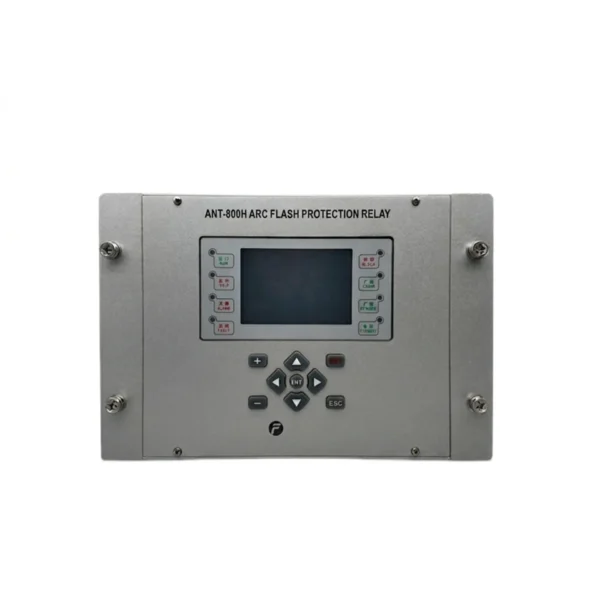
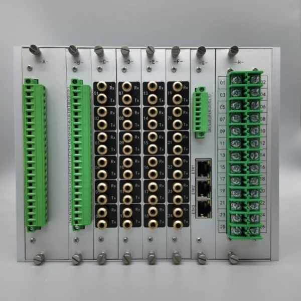
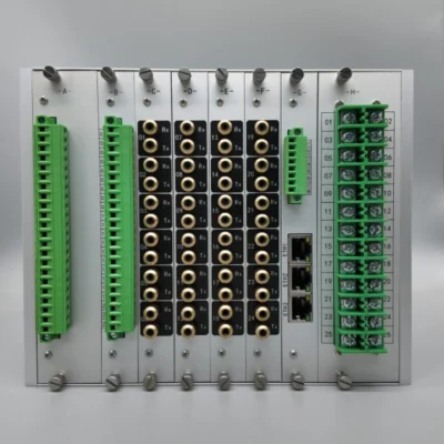
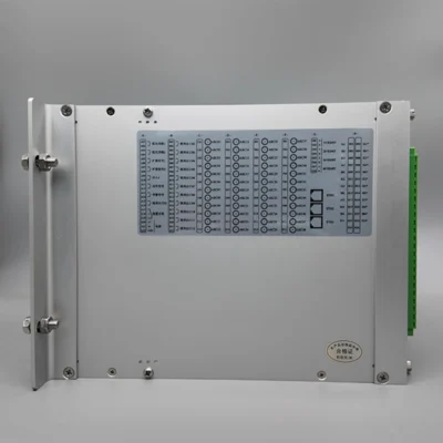
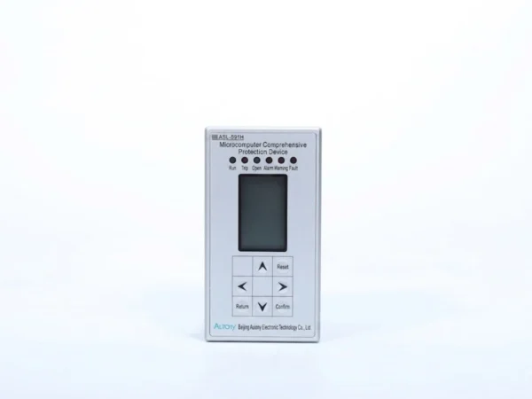
The ATN-800H arc protection relay receives signals from optical arc sensors installed inside the switchgear. When the configured arc detection conditions are met, the relay sends a high-speed trip signal to the circuit breaker. Current inputs and communication interfaces can also be integrated into the protection scheme.
How the Arc Protection Relay Works
Arc protection relays detect internal arcing faults in switchgear and issue a trip command within milliseconds to limit equipment damage. The process follows three clear steps.
1. Arc Sensor Detects the Arc
The arc protection relay receives a high‑speed optical signal from the arc sensor when an electrical arc occurs inside the switchgear. Fibre‑optic or light‑guide sensors installed in each compartment capture the arc’s intense light and send it to the relay within less than 1 ms.
2. Protection Logic Confirms the Fault
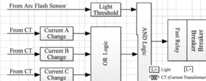
Depending on the protection configuration, the relay can use arc light together with current detection to reduce the possibility of unwanted operation. The relay validates the fault only when both light and overcurrent conditions are met, preventing false trips caused by external flashes or disturbances.
3. Relay Sends the Trip Command
Once the configured protection conditions are satisfied, the arc protection relay activates its trip output and sends a command to the circuit breaker. The relay output operates in 2–7 ms, and the breaker then opens to extinguish the arc and isolate the faulty section.
For a detailed explanation of arc fault protection principles and arc fault relay operation, see our Arc Fault Protection Relay Guide.
Arc Protection Relay Technical Specifications
The following specifications define the main detection, tripping, communication and installation characteristics of the ATN-800H arc protection relay.
| Item |
Specification |
| Working Power |
AC/DC 85-265V |
| Rated Current Input |
5A/1A, 50Hz/60Hz |
| Measuring Range |
0.06-10In |
| Error |
±2.5% |
| Number of ARC Channels |
24/36/48 channels optional |
| Sensor Type |
Visible Light, Ultraviolet Light |
| Transmission Medium |
Plastic Optical Fiber |
| Visible Optical Threshold |
8000lux(±20%) |
| UV Threshold |
5mw/cm²(±20%) |
| UV Spectrum Bandwidth |
280nm~400nm |
| ARC Trip Time |
≤8ms |
| ARC & Current Trip Time |
≤15ms |
| MT Trip Time |
≤15ms |
| Circuit Breaker Failure Delay Time |
100-300ms |
| Relay Output Quantity |
12 Trip Output |
| Communication Interface |
2RS485, 3ETH optional |
| Baud Rate |
4800/9600(Default)/19200 |
| Communication Protocol |
Modbus RTU / Modbus TCP |
| Working Temperature |
-10℃~+55℃ |
| Storage Condition |
-25℃~+70℃, 5-95%RH |
What to Consider When Selecting an Arc Protection Relay
Detection Speed
Response speed is critical for arc protection relays. Quick response limits arc‑flash energy and lowers risks of equipment damage and personal harm. Check total operating time covering sensor response, relay logic and breaker delay. Do not trust nominal specs only; verify test data suited for your actual switchgear conditions.
Number of Protection Zones
Protection zones define independent compartments the unit can monitor, such as busbar, cable and breaker chambers. Match zone quantity to your switchgear layout. Too few zones leave fault areas unprotected, while excessive zones increase costs. Flexible zoning also allows for later substation expansion.
Arc Sensor Type
Optical point sensors and fibre‑optic line sensors are the main options. Point sensors monitor fixed spots, and linear fibre offers continuous coverage for large compartments. Assess on‑site space and light interference. Many relays pair arc light detection with current check to prevent false trips.
Current Blocking Function
Current blocking is an anti‑false‑trip supervision feature. The relay needs both arc light and over‑current signals before sending trip orders. It prevents misoperation from welding sparks or stray light. Ensure adjustable settings so it still responds correctly to low‑magnitude arc faults.
Trip and Communication Interfaces
Trip outputs control circuit breakers, while communication links connect to SCADA for fault logs and alarms. Hard‑contact outputs handle local tripping. Confirm interface compatibility with your existing protection setup and sufficient ports for both onsite switching and remote data transmission.(54词)
Need an Arc Flash Protection Relay for Your Switchgear?
Protect equipment and personnel with high-speed arc flash detection and tripping.
Quick Access
Why Choose Us?
-
Response <1 ms, total clearing time (including breaker) <50 ms
-
Light + current dual detection prevents nuisance tripping
-
Supports fiber-optic and point-type sensors
-
Designed for medium-voltage and low-voltage switchgear
Contact our technical team today to discuss your requirements.
FAQ
Q1: What Is an Arc Protection Relay?
An arc flash protection relay is a high-speed protection device that detects the intense light emitted by an electric arc and sends a trip signal to isolate the fault within milliseconds. It is the core component of any arc flash protection relay system, providing fast fault clearing that conventional overcurrent relays cannot achieve. As a dedicated arc flash detection relay, it responds in less than 1 ms, reducing incident energy and minimizing equipment damage.
Q2: How Does an Arc Protection Relay Work?
An arc flash protection device uses fiber-optic or point-type sensors installed inside switchgear enclosures to monitor for arc light. When light exceeds a preset threshold and fault current is present, the device sends a trip signal to the upstream breaker. This dual-condition logic — used in modern arc flash relay protection schemes — ensures reliable tripping for actual arc faults while preventing nuisance tripping from external light sources.
Q3: What Is the Difference Between an Arc Protection Relay and an Overcurrent Relay?
Conventional overcurrent relays detect faults by measuring current magnitude, which can take 25–45 ms or more. An arc flash relay detects the light from an arc almost instantly — typically within 1 ms. By combining arc flash detection and protection, the relay significantly reduces total fault clearing time (including breaker operation) to under 50 ms, limiting arc energy exposure.
Q4: What types of sensors are used in arc flash protection equipment?
Arc flash protection equipment supports both fiber-optic sensors (for long-distance light detection across large enclosures) and point-type sensors (for localized detection in specific compartments). This flexibility allows optimal sensor placement for any switchgear configuration. The arc flash detection relay continuously monitors sensor signals and initiates tripping when both light and current conditions are met.
Q5: Where Is an Arc Protection Relay Used?
Arc flash protection equipment is installed in medium-voltage and low-voltage switchgear, motor control centers (MCCs), substations, power plants, and renewable energy facilities — anywhere arc flash hazards pose risks to equipment and personnel. An arc flash protection relay system is particularly valuable in applications where fast clearing time is critical for personnel safety and equipment protection.
Q6: Does the arc flash relay trip on light alone?
No. The arc flash relay uses a dual-condition logic: it trips only when both arc light is detected and fault current is present. This prevents nuisance tripping from external light sources such as camera flashes, welding arcs, or direct sunlight. This current-blocking feature is standard in most arc flash protection equipment, ensuring security while maintaining high-speed operation for real arc events.
Q7: Can the arc flash detection and protection system be retrofitted?
Yes. The arc flash detection and protection system is designed for both new installations and retrofit projects. Compact dimensions, flexible sensor mounting options, and multiple communication interfaces ensure easy integration into existing switchgear panels without major modifications.
Q8: What communication protocols does the arc flash protection relay system support?
The arc flash relay supports standard protocols including Modbus RTU, Modbus TCP, and IEC 61850 for seamless integration with SCADA and substation automation systems. This allows remote monitoring of arc flash protection equipment status, event reporting, and system-wide coordination.
Q9: Does the arc flash protection device provide fault recording?
Yes. The arc flash protection device records event logs with time stamps and fault data, enabling post-event analysis and helping identify the root cause of arc flash incidents. This data is essential for improving system safety and maintenance planning.
Q10: How does arc flash detection and protection improve personnel safety?
Arc flash detection and protection reduces fault clearing time from hundreds of milliseconds to under 50 ms, dramatically lowering incident energy released during an arc flash. This reduces burn hazards, minimizes equipment damage, and provides a safer working environment for operating and maintenance personnel. An arc flash protection relay system is a critical component of any comprehensive electrical safety program.


xiao zhang –
This arc flash protection device delivers ultra-fast tripping to restrain short-circuit damage caused by internal cabinet arc faults, equipped with superior anti-interference performance for safe operation of medium-voltage switchgear in substations.
Jack –
Works reliably in substations — a dependable product.