
-
Leon Zhang Sales Manager
-
Email: sale@relayprotect.com
-
Phone/WhatsApp: +86 13655813266

Arc Protection: 10 ms Trip, Light and Current Criteria
How does an arc protection relay clear a fault so quickly?
An arc protection relay trips on two criteria at once: light inside the compartment and current above a threshold. Light alone reacts in 1 to 3 ms but false-trips on a camera flash; current alone is too slow. Together they clear the arc in 10 to 20 ms, before the pressure wave reaches the door. An internal arc begins as a small insulation breakdown and reaches full short-circuit energy within tens of milliseconds, so the hazard is described in calories per square centimetre and trip time rather than amperes alone. Practically every new scheme pairs an optical channel with a current criterion, because light alone cannot tell a real arc from daylight on a lens. Switchgear requirements follow IEC 62271-200:2021, arc-rated equipment follows IEC 61482-2:2018, arc-resistant testing follows IEEE C37.20.7, and the relays are type-tested to the IEC 60255 series. Setting review and quotation within 12 hours, MOQ 1, 7-15 working days.
An arc protection relay trips on two criteria at once: light inside the compartment and current above a threshold. Light alone reacts in 1 to 3 ms but false-trips on a camera flash; current alone is too slow. Together they clear the arc in 10 to 20 ms, before the pressure wave reaches the door.
Switchgear requirements follow IEC 62271-200:2021, arc-rated clothing and equipment follow IEC 61482-2:2018, and arc-resistant switchgear testing follows IEEE C37.20.7-2017.
Written by Leon Zhang, Protection Application Engineer. Technical review by the relayprotect.com engineering team. Last reviewed October 2026.
Arc fault protection is the protection method that identifies an arcing fault inside switchgear by its light and current signature, then trips the breaker in 10 to 20 ms, before the arc reaches its full incident energy.
At a Glance
- Light detection reacts in 1 to 3 ms; total clearing time is 10 to 20 ms including breaker opening.
- Dual criterion, light plus current, is what keeps a camera flash from tripping the lineup.
- Current threshold is set just above the highest load current, typically 1.2 to 2 times rated.
- One sensor per compartment, with extra sensors at cable entries and behind doors.
- Incident energy falls with the square of clearing time, so 20 ms instead of 100 ms cuts it by 25 times.
- Arc-rated switchgear to IEC 62271-200 limits damage but does not clear the fault.
- Fibre loops suit long line-ups; point sensors suit compartments with a direct line of sight.
Arc Protection Methods Compared
Three arc flash protection methods are in use on live project work. The optical method reads the light of the arc through a fibre or a lens and is the fastest of the three. The current-signature method looks at the flat-topped, high-frequency waveform a sustained arc produces, which a bolted fault does not. The pressure method reads the pressure rise inside a sealed compartment and is mostly found in older air-compressed designs. Practically every new scheme pairs the optical channel with a current criterion, because light alone cannot tell a real arc from daylight falling on a lens.
Standards and Trip Times in Brief
Three families of document shape a purchase of this kind. IEC 62271-200 gives the internal arc classification, written IAC, for high-voltage switchgear assemblies with a controlled arc inside the enclosure. IEC 60947-9-2 adds the device level rules for arc-fault protection devices in low-voltage switchgear, and the IEC 60255 series is what the protection relays themselves are type-tested to, including the response times printed on a datasheet. On the American side, IEEE C37.20.7 covers arc-resistant metal-enclosed switchgear, IEEE 1584 calculates the incident energy and the arc flash boundary, and NFPA 70E fixes the PPE category a technician has to wear. Arc detection relays are type-tested under the IEC 60255 series and report over IEC 61850 inside a smart substation.
Selecting a relay for a live project?
Send the system voltage, CT ratio and tripping scheme. Our engineers confirm the model and reply within 12 hours.
Where to Start, by Your Role
Work through the hazard section first if you are sizing the scheme, the selection section if you are writing a specification, and the troubleshooting section if the panel is already in service. Each section states the fault, the setting that clears it and the voltage class it applies to, so you can skip the parts that do not match your switchgear.
Hazards of Arc Flash in Power Systems
An internal arc is the event that an arc detection scheme exists to stop. It begins as a small insulation breakdown and reaches full short-circuit energy within tens of milliseconds, so the hazard is described in calories per square centimetre and in trip time, not only in amperes.
Personal Injuries
Arc flash generates extreme high temperature from 3,000℃ to 20,000℃, leading to severe burns, eye damage from intense light, blast impact injuries and toxic fume poisoning.
The blast also throws molten metal and shard glass out through the door, and the copper vapour carried in the plasma leaves a toxic cloud that reaches the room before the fire brigade does.
Equipment Destruction
High heat melts busbars, cable insulation and switchgear components. Huge short-circuit current burns out breakers and transformers, resulting in equipment scrapping.
Once the arc runs past the first cycle the busbar melts and the usual repair is a new cubicle rather than a new breaker.
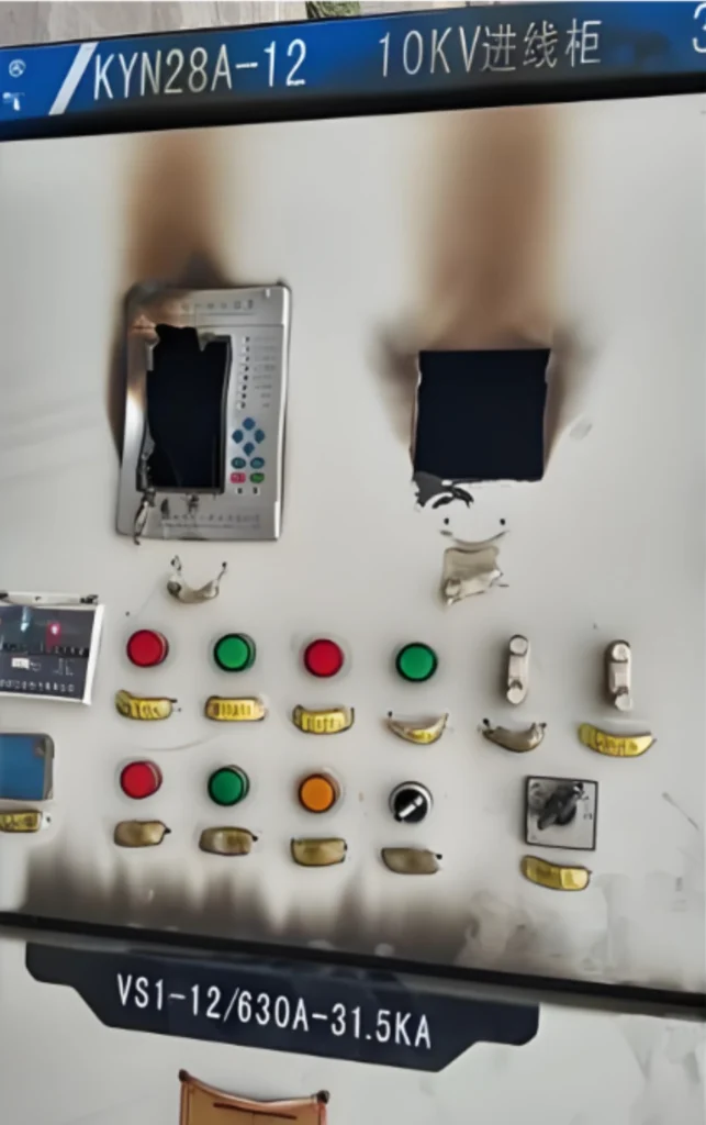
That last row is where the two technologies part company. An overcurrent relay needs 3 to 10 cycles of fault current before its inverse-time characteristic reaches pickup, while an arc protection relay acts on the first millisecond of light and leaves the breaker 15 to 40 ms to finish the job.
Power Outage Losses
Arc short-circuit causes unwanted cascading tripping, leading to blackouts and shutdown of industrial plants, PV stations and data centers with heavy economic losses.
Restart cost after a busbar replacement runs into weeks for a continuous process plant, which is why the interruption number belongs in the design case and not only in the insurance file.
Secondary Disasters
High temperature ignites combustibles inside cabinets and triggers fire accidents in power distribution rooms.
Fire reaching the cable tunnel spreads to the neighbouring cubicles, so a single arc rarely stays a single asset event.
What Is Arc Fault Protection ?
The scheme is applied through dedicated arc detection devices that watch a switchgear compartment for the light and the current of an arcing fault. The device reports to a trip relay, and that relay opens the breaker while the arc is still inside its first half cycle.
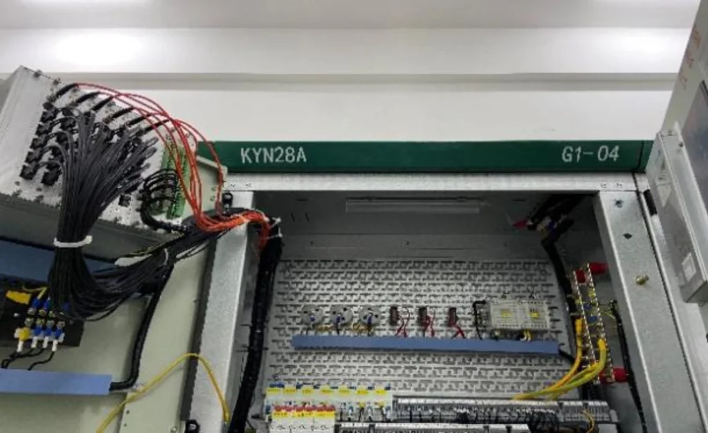
An electrical arc forms when electric current arcs across air between conductors or to earth, generating extreme heat over 20,000°C, while arc fault protection devices detect such arcs to avoid equipment damage, fire risks and personal hazards.
Unlike traditional relays that monitor only current or voltage, a modern arc detection system combines optical detection, current verification and ultra-fast trip logic. It reacts to the arc itself instead of waiting for a threshold that a high-impedance arc may never cross.
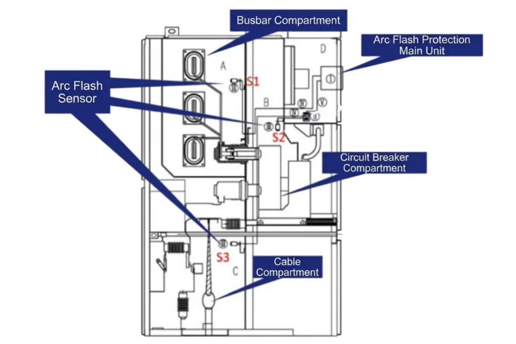
Coverage decides whether the scheme works. The sensor has to sit inside the compartment it protects: a fibre in the busbar compartment, a lens in the cable compartment, and a second fibre wherever two compartments meet at a door. Nothing outside the enclosure can see the arc, which is why a retrofit project starts with the cubicle drawing rather than with the arc protection relay.
Arc fault protection requirements
Overseas Standards
IEC: IEC62271-200 (IAC internal arcing test), IEC60947-9-2 (optical arc protection), IEC61641 (switchgear arcing test).
ANSI/IEEE: IEEE C37.20.7 (MV switchgear arc resistance), IEEE 1584 (arc flash energy calculation), NFPA70E (site arc safety).
Those two lines describe the enclosure duty and the site duty. IEC 62271-200 classifies an assembly by its IAC rating, that is the test current and the test duration the enclosure survives with a controlled arc burning inside it. IEC 60947-9-2 adds the device level rules for arc-fault protection devices in low-voltage switchgear, and the IEC 60255 series is what the relay chassis itself is type-tested to.
Mandatory Installation Requirements
North America: Dual-criterion arc detection (light + current) is required for ≤35kV air-insulated switchgear without bus differential protection, power plant auxiliary systems, large industrial & commercial distribution rooms, and PV booster stations. Switchgear must pass IAC internal arcing type tests.
Middle East (DEWA/SECO): Arc detection is mandatory for industrial substations over 5MVA and new prefabricated substations, with switchgear complying with IEC62271 arc-resistant requirements.
Europe: Arc detection shall be installed for busbars and switchgear in power plants, data center substations and high-risk chemical distribution facilities.
Core Technical Parameters
Optical threshold: 1~10mW/cm² (anti-light interference). The setting has to stay above the light a torch or a window can deliver and below the level the arc produces in its first millisecond.
Tripping speed: ≤10ms (single light criterion); ≤20ms (light + current dual criterion). The figure on the datasheet covers the arc protection relay output only, and the breaker still needs 15 to 40 ms of its own on top.
Current setting: 0.6~6×In, ensuring no false tripping under no-load conditions. The band keeps a bright lens from clearing an unloaded panel while still seeing the low current of a high-impedance arc.
Communication: IEC61850 protocol for smart substation system compatibility. Where a station has no 61850 stack, Modbus or Profibus carries the same trip and the same event records into the SCADA master.
Why traditional protection relays aren’t enough
Overcurrent relays and earth fault relays react only after fault current reaches a set level. Many arc faults generate currents below this threshold initially, delaying the trip and increasing the risk of fire or equipment damage.
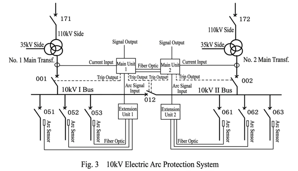
That gap is why panels built a decade ago get retrofitted. The switchgear stays where it is, and the arc detection device and its fibres are added to the existing busbar compartment. Typical arrangements are shown below:
Differences Between an Arc Protection Relay and Conventional Protection
| Protection Type | Detects |
|---|---|
| Overcurrent Relay | Excess current only |
| Earth Fault Relay | Ground faults |
| Arc Fault Protection | Electrical arcs, arc flashes |
How does arc fault protection work
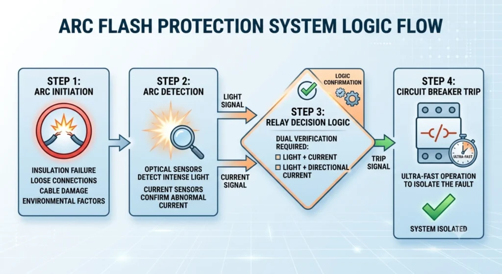
Step 1: Arc Initiation
Causes are insulation failure, loose connections, cable damage and environmental factors. At 1 to 20 kV the fault usually starts at a termination, a loose busbar bolt or a nicked cable wall, and the resistance of that path decides how much current the arc will draw.
Step 2: Arc Detection
Optical sensors read the arc light. A fibre pointed at the busbar sees the flash in the first millisecond, and a relay set to single-criterion mode fires on that channel alone.
Current sensors confirm abnormal current. The second channel is what keeps a reflected lamp beam or a welding flash outside the cabinet from clearing a healthy feeder.
Step 3: Relay Decision Logic
Dual verification: light + current, or light + directional current. In the scheme described here, the arc protection relay adds the two signals in one logic path, applies the current setting and holds the trip until both conditions are true.
Step 4: Circuit Breaker Trip
The relay output closes the trip circuit and the breaker opens. From first light to arc extinction the chain runs at 10 to 20 ms through the relay and 15 to 40 ms more through the breaker itself.
Customer question: “Why did an arc fault occur in a newly installed panel?”
Often, even minor installation errors or environmental factors can trigger arc faults, emphasizing the need for dedicated protection.
Benefits
- Faster than any current-based function: the scheme acts in the first millisecond of the arc instead of waiting for a pickup current a high-impedance arc may never reach.
- Less incident energy: clearing in 20 ms rather than after two cycles removes most of the energy IEEE 1584 would otherwise calculate into the PPE category.
- Lower equipment loss: the busbar and the cable terminations inside the compartment survive, and the cubicle comes back into service instead of being scrapped.
- Compliance evidence: the event record and the measured trip time are what you show an auditor asking how the arc flash boundary was controlled.
- Fewer outage hours: the fault is isolated at the compartment, so the rest of the busbar stays energised.
Common Causes of Arc Faults
Arc faults start in four kinds of place, and each kind has its own position in the cubicle. Mechanical and electrical defects come from installation and from thermal cycling, environmental defects come from the room, and human factors cover maintenance and wiring. The table below is the list we work through at commissioning.
| Fault Category | Specific Fault/Risk Items |
|---|---|
| Mechanical | Loose busbars, cable terminations |
| Electrical | Insulation breakdown, overheating |
| Environmental | Moisture, dust, condensation |
| Human Factors | Maintenance errors, wiring mistakes |
Where Arc Protection Is Required
Four application fields drive most of the orders. In a PV plant the requirement sits on the DC side of the array, where an arc can burn for a long time with no overcurrent for the inverter to see. In an industrial plant it sits in the medium-voltage switchgear. In a substation it sits on the busbar and the cable compartments. In a data centre it sits under the critical load, where an arc means a fire and a load transfer at the same moment.
| Application Field | Core Protection & Detection Function |
|---|---|
| Solar PV Systems | 1. DC arc fault detection2. Inverters and combiner box protection |
| Industrial Switchgear | Internal arc detection for medium-voltage equipment |
| Substations | Busbar and cable compartment protection |
| Data Centers | Critical power system protection |
Main Features and Field Installation of an Arc Detection System
Features
An arc detection relay for this duty carries six functions that a general purpose feeder relay does not list. What the datasheet usually enumerates:
- Ultra-fast detection: 10 ms on the light channel, 20 ms on the light and current channel.
- Multiple optical sensors: several fibres or lenses on one chassis, so a single relay covers a whole switchgear lineup.
- Current verification: a current criterion from 0.6 to 6 times rated current that suppresses false trips from external light.
- Communication protocols: Modbus, IEC 61850 and Profibus, so the trip and the event record reach the station LAN.
- Event recording and diagnostics: fault time, peak current, light level and sensor health, kept for the report you need six months later.
- Self-monitoring: the arc protection relay watches the sensor loop and reports a broken fibre instead of silently missing the next arc.
Field Mounting
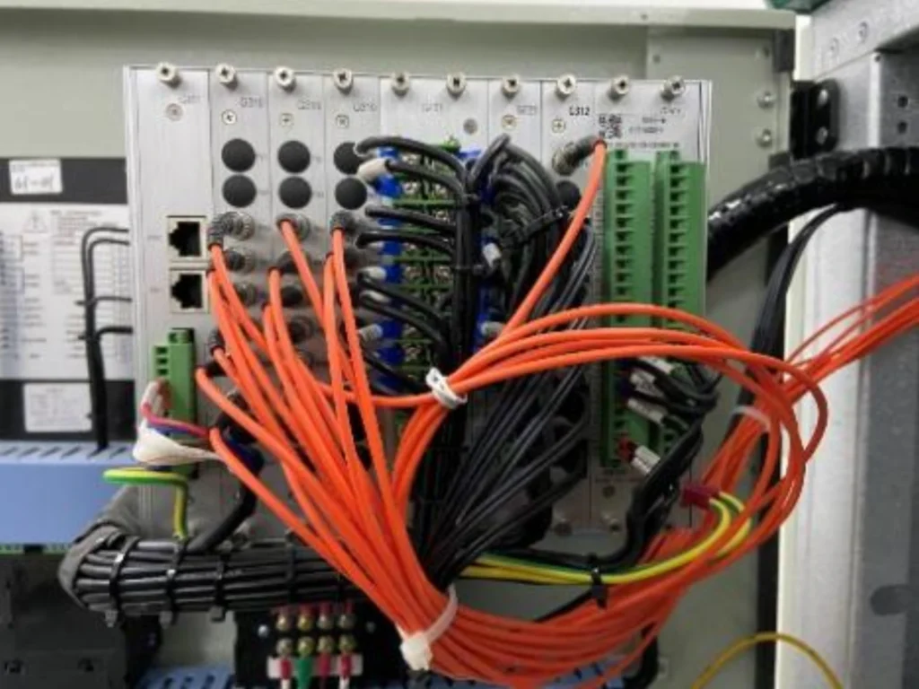
The fibre runs from the sensor head into the relay through a sealed entry. The sensor is fixed on the opposite wall of the compartment from the expected arc point, with a clear line of sight to the busbar, and the bend radius matters: a fibre tighter than its specification loses light and lifts the effective threshold.
How to Select Arc Fault Protection
Selection runs through six decisions in this order. Getting the order wrong is what produces a relay that cannot see the compartment it was bought for.
- System voltage: low, medium or high. A 400 V board, a 12 kV air-insulated lineup and a 36 kV ring main unit need different sensor types and different creepage.
- Protection zone: a single compartment, a whole switchgear lineup, or the busbar alone. The zone fixes the number of sensors and the number of trip outputs.
- Sensor quantity and placement: one per compartment at the busbar end, with the head aimed at the arc position shown on the cubicle drawing.
- Environmental conditions: indoor or outdoor, wet or dusty, which decides the sensor IP rating and whether the fibre needs a metallic sheath.
- SCADA integration: Modbus, IEC 61850 or Profibus, and how many event records the station has to hold.
- Future scope: spare sensor inputs and a spare trip output, so an extra feeder does not turn into a new relay order.
The wider selection work, including the CT ratios and the coordination study that has to sit behind this function, is written up separately in the notes on medium voltage protection relay selection.
Troubleshooting Common Problems
Three faults account for most service calls. The scheme trips when it should not, it does not trip when it should, and it cannot be read from the control room. The cause is nearly always installation or a setting, not the arc protection relay hardware.
False Arc Fault Alarms:
Causes are a dirty or greasy lens, light reflected off a polished busbar into the sensor, and a threshold left at its factory minimum.
Clean the lens with a dry cloth, move the sensor off the specular line, and raise the optical threshold until a torch held against the cabinet does not trip the scheme.
Relay Fails to Detect Arc Fault:
Causes are a broken or over-bent fibre, a sensor fitted outside the compartment it protects, and a logic element that was never enabled at commissioning.
Test each sensor with a calibrated light source, confirm the fibre route against the drawing, and read the relay self-supervision flags before touching any setting.
Communication Failures:
Causes are a wrong station address, a broken Ethernet or RS485 segment, and a slave that speaks one protocol while the master polls another.
Verify the network map against the relay address list, replace the segment cable, and bring the relay firmware to the revision the integration note specifies.
FAQ: Questions Engineers Ask Before Ordering
Do bathroom lights need to be arc fault protected?
Per NEC, bathroom lights carry no mandatory AFCI requirement, but the bathroom outlets do require GFCI, and AFCI can be added on top of that for fire protection.
The distinction matters when you write the specification: AFCI, ANSI function 90, works on the live conductors of a branch circuit at socket level, while a compartment-based arc detection device protects the switchgear itself and is no substitute for the code requirement at the outlet.
How fast should it operate?
Modern systems see the arc in 1 to 10 milliseconds and clear it within the contract figure of 20 ms on the light and current channel.
The breaker adds 15 to 40 ms of its own, so quote 40 ms as the worst case seen at the terminals rather than the figure printed on the relay datasheet.
Can it prevent electrical fires?
Yes, with a limit worth stating plainly. Clearing the arc in 20 ms removes most of the incident energy, yet an arc that runs for two full cycles will ignite whatever is inside the cabinet, and the relay cannot undo that afterwards.
Detection keeps the damage small. Sound termination and correct torque work keep it from starting in the first place.
Are arc fault protection systems required in solar PV?
Many installations use them to meet the safety standard and to cut the fire risk. The requirement is sharper on the DC side.
A DC arc at 1000 V has no natural current zero, so it burns rather than clears, and a fault inside a string is exactly what an inverter will not see. A detection device on the DC combiner box plus a dual-criterion device on the AC side is the arrangement most utilities ask for on a booster station.
How many sensors are needed?
Count compartments, not cubicles. One sensor per compartment, with an extra one wherever a door or a cable tray gives the arc a second path, is the working rule.
A twelve feeder lineup built around three busbar sections usually runs between eight and fourteen sensors on a single relay chassis.
Can it integrate with SCADA systems?
Yes. Modbus over RS485 carries the measurements and the event records to a local HMI.
IEC 61850 GOOSE carries the trip across the station LAN without a hardwired run, which is what a smart substation design asks for whenever the breaker trip coil sits at the far end of the room.
What causes nuisance trips?
Three settings cause almost all of them. The optical threshold left at its minimum, the current criterion set below the inrush of a large motor, and a sensor aimed straight at a door window.
Raising the threshold and re-aiming the head usually clears the problem without any change to the hardware.
How often should the system be tested?
Annual is the usual answer and the practical minimum for a utility asset.
Test the trip path with secondary injection, shine a calibrated light source into each sensor in turn, and record the result. The sensor loop degrades quietly, and a lens that is already 60 percent dark will still pass a visual inspection.
When Arc Protection Is Not the Right Answer
An arc protection relay earns its cost in metal-clad switchgear with a person standing in front of it. Four situations are better served by a different measure, and fitting sensors there adds maintenance without reducing risk.
- Outdoor switchyards and open busbars: an arc in open air does not build pressure in a compartment, and the light sensor sees sunlight, so distance protection and interlocking do the job.
- Low-voltage distribution boards below 400 V with low fault energy: the incident energy is often below the level where arc-rated PPE alone is sufficient, and the relay adds a sensor to every enclosure.
- Switchgear already type-tested as arc-resistant to IEC 62271-200 with a defined access level: the design contains the arc, and the remaining risk is at the cable entry, which a single sensor there covers.
- Retrofits where the fibre cannot be routed without drilling through the pressure boundary: cutting the enclosure voids the type test, and the protection ends up reducing the integrity it was meant to improve.
Standards and Edition Reference
The edition years below are the issues in force. IEC 62271-200 moved to the 2021 edition, and arc-resistant ratings quoted against the 2011 edition describe a different test sequence.
| Standard | What it covers | Edition |
|---|---|---|
| IEC 62271-200:2021 | AC metal-enclosed switchgear and controlgear up to 52 kV | 2021 |
| IEC 61482-2:2018 | Live working: protective clothing against the thermal hazards of an arc | 2018 |
| IEEE C37.20.7-2017 | Guide for testing metal-enclosed switchgear for arc resistance | 2017 |
| ANSI/IEEE C37.2-2022 | Device function numbers and acronyms | 2022 |
| IEC 60255-1:2022 | Protection relays: common requirements and test conditions | 2022 |
| NFPA 70E-2024 | Standard for electrical safety in the workplace | 2024 |
Table 5. Standards cited in this article and the edition each reference follows.
Conclusion
An arc protection relay pays for itself in the compartments someone stands in front of, and nowhere else. Internal arc detection has moved from a utility option to a default line item. The function that used to be reserved for a bus zone now ships on auxiliary boards, PV booster stations and data centre distribution, because the cost of the scheme is small next to the cost of one scrapped cubicle.
Whether the site is a solar farm, an industrial plant, a substation or a data centre, the decisions that decide whether the scheme works are the same three: sensors inside the compartments, a current criterion above the largest inrush, and a trip path proven by secondary injection at handover.
If the panel is already built, start from the cubicle drawing and the fibre route rather than from the relay. Most schemes that underperform are missing one sensor inside one compartment, and no setting change in the relay will cover that gap.
Technical Reference
| Standard | Scope | Use For |
|---|---|---|
| IEC 62271-200 | High-voltage switchgear assemblies, internal arcing classification (IAC) | Selecting an arc-resistant enclosure and rating the assembly |
| IEC 60947-9-2 | Low-voltage switchgear, arc-fault protection devices (AFPD) | Device level requirements for an optical arc detector |
| IEC 60255 series | Measuring relays and protection equipment | Type tests and the response times printed on a datasheet |
| IEEE C37.20.7 | Metal-enclosed switchgear, arc-resistant design (medium voltage) | North American medium-voltage switchgear duty |
| IEEE 1584 | Calculation of arc flash incident energy and the arc flash boundary | Size the protection and set the PPE category |
| NFPA 70E | Electrical safety in the workplace | PPE selection, approach limits and the arc flash boundary |
| IEC 61850 | Substation communication and GOOSE messaging | Carrying the trip and the records onto the station LAN |
Standard revisions change from year to year, so confirm the current edition with the issuing authority before a specification is issued. Some switchgear data sheets also cite IEC 61641 for assembly level arcing duty; its scope belongs to the test report rather than to a general assumption.
Related Reading
- Protection of switchgear
- Medium voltage protection relay selection
- Arc flash protection relay
- Short-circuit protection relay
- How to set an overcurrent protection relay correctly
- Protection and control panels
If the selection has to be checked against your switchboard, send the single-line and the ratings.
About Author

Hello, I'm Leon Zhang. I have 15 years of experience in the power relay protection industry with extensive pre-sales and after-sales project experience. Our company specializes in various complete sets of relay protection and automation equipment. I can assist customers in solving all practical on-site project challenges and provide optimal integrated solutions.
Tell Us Your Requirement



High Quality
Stable performance, reliable design, ensuring safe operation for power system protection and grid stability.
Fast Delivery
Timely delivery to support your urgent orders and project schedules efficiently and professionally at any time.
Best Warranty
Professional Warranty: Reliable after-sales support for stable relay protection and long-term customer satisfaction.