

-
Leon Zhang sales consultant
-
Email: zxl635973785@gmail.com
-
Phone/WhatsApp: +86 13655813266
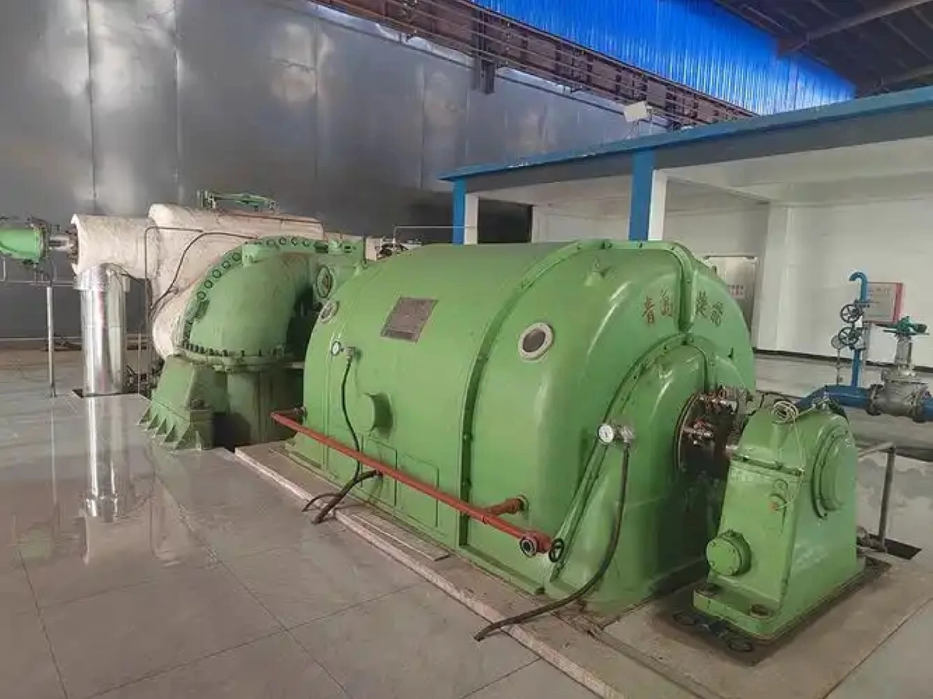
Generator Relay Protection System: Scheme, Devices, Functions and Testing
What Is a Generator Relay Protection System?
A generator relay protection system is a coordinated secondary protection and control system designed to perform multiple critical functions: detect generator faults, isolate damaged equipment, monitor operating conditions, and interface with plant control and SCADA systems. Unlike a single protection relay, the system encompasses all sensing, logic, control, communication, and actuation elements that work together to ensure generator safety and operational reliability.
System Architecture
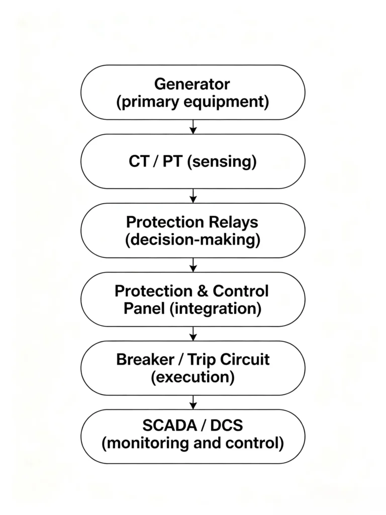
The typical architecture of a generator protection system follows a hierarchical signal flow from the primary equipment to the control center:
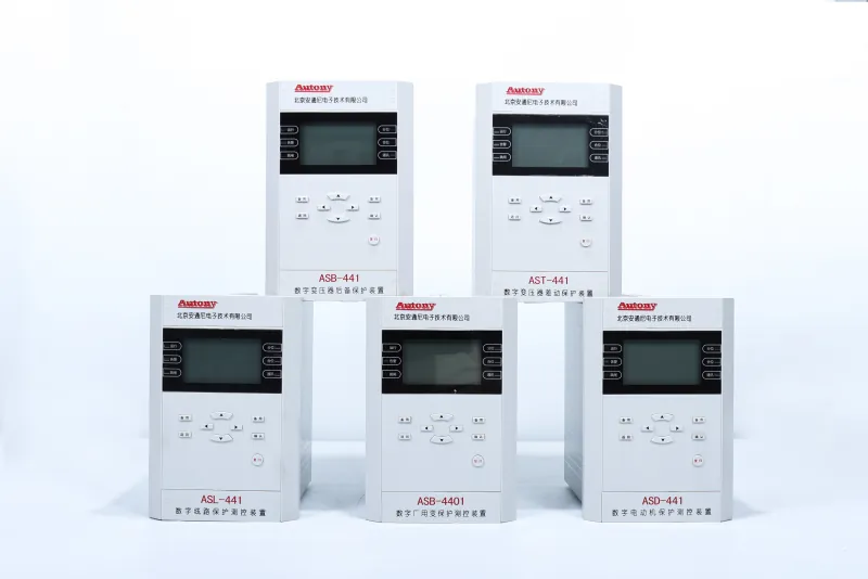
Components of the Generator Relay Protection System
A complete generator relay protection system consists of multiple functional subsystems working in coordination:
| Component | Function |
|---|---|
| Primary Equipment | Generator stator, rotor, and associated electrical machinery |
| Sensing Devices | Current transformers (CTs) and voltage transformers (PTs/VTs) that measure electrical parameters |
| Protection Relays | Intelligent devices that evaluate measurements and make trip decisions |
| Protection & Control Panel | Physical enclosure integrating relays, switches, indicators, and wiring terminals |
| Breaker / Trip Circuit | Circuit breakers and auxiliary trip relays that execute isolation commands |
| SCADA / DCS Interface | Communication links for remote monitoring, control, and data acquisition |
Functional Breakdown of the Generator Relay Protection System
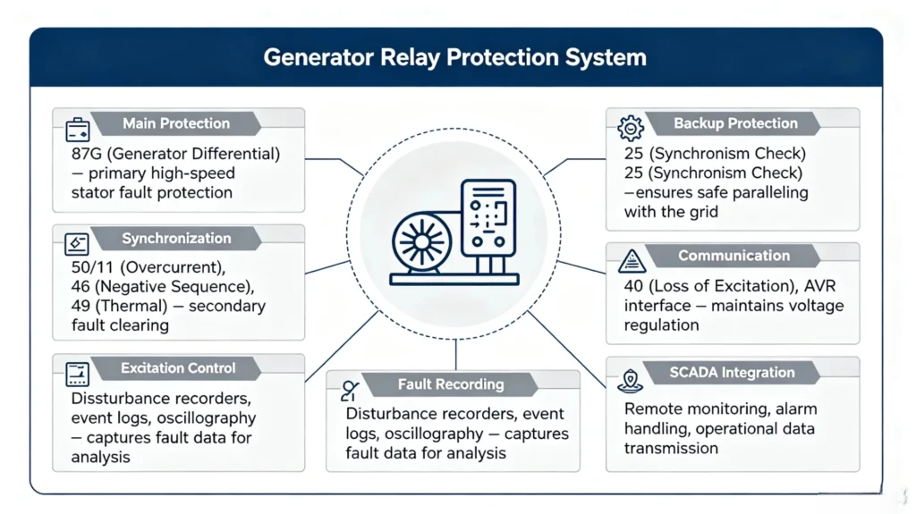
System-Level Capabilities
A properly designed generator relay protection system provides:
- Comprehensive Fault Coverage – Detection of all internal and external fault conditions
- Redundancy – Backup protection ensures fault clearing even if primary protection fails
- Condition Monitoring – Continuous assessment of generator operating health
- Control Integration – Coordination with excitation systems, governors, and synchronizing equipment
- Data Recording – Fault records and event logs for post-event analysis
- Remote Operation – Full visibility and control through SCADA/DCS interfaces
Generator Relay Protection Scheme
A generator relay protection scheme is a coordinated set of protection functions divided into three layers: main protection, backup protection, and generator transformer protection. Each layer serves a distinct role in ensuring comprehensive fault coverage.
Protection Scheme Diagram
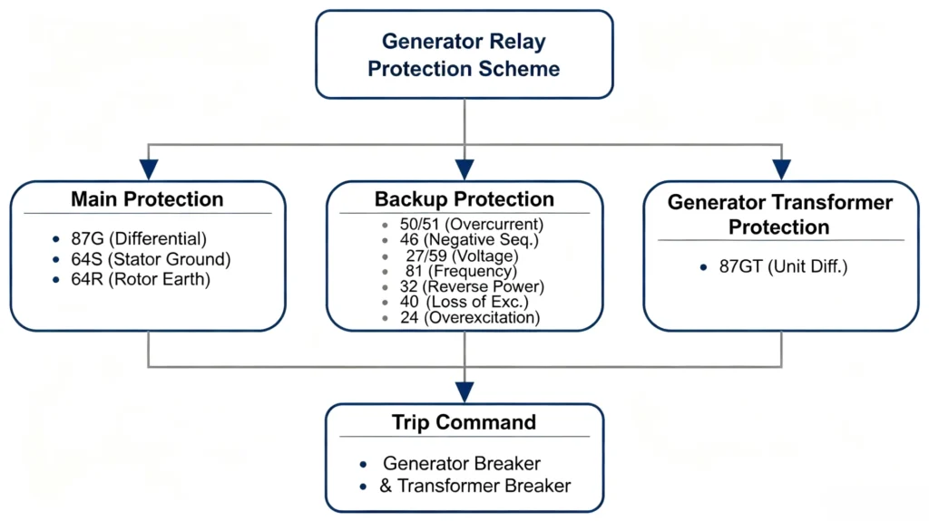
Main Generator Protection
Main protection is the first line of defense, operating instantaneously for internal generator faults.
| Function | ANSI | Purpose |
|---|---|---|
| Generator Differential | 87G | Internal stator phase faults – compares terminal vs neutral CT currents |
| Stator Ground Fault | 64S | Stator winding ground faults – provides 100% winding coverage |
| Rotor Earth Fault | 64R | Rotor insulation monitoring – detects ground faults before second fault occurs |
Key characteristic: Instantaneous trip – no intentional time delay.
Generator Backup Protection
Backup protection provides secondary coverage with time delay to allow coordination with downstream protection.
| Function | ANSI | Purpose |
|---|---|---|
| Overcurrent | 50/51 | Backup for external faults and overloads |
| Negative Sequence | 46 | Unbalanced load protection – prevents rotor overheating |
| Voltage Protection | 27/59 | Over/under voltage protection |
| Frequency Protection | 81 | Over/under frequency protection |
| Reverse Power | 32 | Prevents generator motoring – protects prime mover |
| Loss of Excitation | 40 | Excitation failure detection – prevents rotor overheating |
| Overexcitation | 24 | V/Hz protection – prevents core saturation |
Key characteristic: Time-delayed operation for selective coordination.
Generator Transformer Protection
When the generator and step-up transformer are directly connected without a breaker between them, 87GT protection is required.
| Function | ANSI | Purpose |
|---|---|---|
| Generator Transformer Differential | 87GT | Integrated differential protection for generator + transformer + connection zone |
Why 87GT protection is needed:
- No circuit breaker separates the generator and transformer
- A fault in either machine rapidly affects the other
- Connection zone is not covered by standalone 87G or 87T
- Provides single, simultaneous trip for both generator and transformer breakers
Additional features:
- Harmonic restraint prevents tripping on transformer inrush current
- CT configuration includes generator terminal CTs and transformer high-voltage CTs
Generator Protection Relay Functions
| ANSI | Protection Function | Purpose |
|---|---|---|
| 87G | Generator Differential | Internal stator faults |
| 64S | Stator Earth Fault | Stator ground faults |
| 64R | Rotor Earth Fault | Rotor insulation faults |
| 50/51 | Overcurrent | Phase faults / backup |
| 32 | Reverse Power | Prevent generator motoring |
| 40 | Loss of Excitation | Excitation failure |
| 46 | Negative Sequence | Unbalanced current |
| 24 | Overexcitation | V/Hz protection |
| 27/59 | Under/Overvoltage | Voltage abnormalities |
| 81U/81O | Under/Overfrequency | Frequency abnormalities |
Generator Protection and Control Panel
A generator protection and control panel is a physical enclosure that integrates all protection, control, monitoring, and communication devices required for safe generator operation. It houses the protection relay along with auxiliary components for fault detection, breaker control, alarm handling, and operator interface.
Panel Functions
| Function | Description |
|---|---|
| Protection Relay | Intelligent core executing protection logic and issuing trip commands |
| Trip Circuit | Auxiliary relays transmitting trip commands to breakers |
| Breaker Control | Manual/automatic close/open control with status indication |
| Measurement | Real-time display of voltage, current, power, frequency |
| Alarm | Visual/audible indications for abnormal conditions |
| Event Recording | Time-stamped logging of operations and alarms |
| Communication | SCADA/DCS interface via standard protocols |
| HMI | Local operator interface for control and diagnostics |
Protection Relay vs Protection Panel
| Aspect | Protection Relay | Protection & Control Panel |
|---|---|---|
| Scope | Intelligent device only | Complete physical system |
| Function | Decision-making and trip initiation | Full protection, control, monitoring, and interface |
| User Interface | Limited on-device display | Full HMI with measurements, controls, alarms |
Panel Design Considerations
- Enclosure: IP rating for indoor/outdoor/harsh environments
- Power Supply: Redundant DC supplies for critical applications
- CT Termination: Shorting facilities for safe CT handling
- Lockout Function: Manual reset after trip to prevent auto-reclosure
- Test Facilities: Test blocks for secondary injection without wiring disturbance
Generator Protection SCADA and Communication
Modern generator protection relays are integral nodes in plant-wide monitoring and control. Communication capabilities enable real-time data sharing with SCADA, allowing operators to monitor generator health, respond to alarms, and analyze faults from a central control room.
Data Acquisition
The relay continuously collects and transmits operational data to SCADA systems:
| Data Category | Examples |
|---|---|
| Analog | Voltage, current, power, frequency, temperature |
| Status | Breaker position, relay health, alarm conditions |
| Events | Trip commands, protection operations, self-check events |
| Fault Records | Waveforms, pre/post-fault data, sequence of events |
Remote Monitoring and Control
Monitoring:
- Real-time display of measurements and status
- Alarm annunciation and acknowledgment
- Event log and fault record retrieval
Control:
- Remote breaker open/close
- Remote lockout reset (where permitted)
- Setting group switching
Key consideration: Cybersecurity measures are essential for remote control. Critical trip functions typically remain hardwired for reliability.
Event and Alarm Management
- Event Recording: Millisecond-accurate time-stamping of every operation and status change
- Sequence of Events (SOE): Chronological ordering of events for fault reconstruction
- Alarm Categorization: Severity-based classification (warning, critical, emergency) for operator prioritization
- Alarm Acknowledgment: Confirms operator awareness of important events
Communication Protocols
| Protocol | Typical Application |
|---|---|
| IEC 61850 | Modern digital substations; GOOSE messaging for high-speed interlocking |
| IEC 60870-5-104 | WAN communication between control centers and remote substations |
| IEC 60870-5-101 | Serial RTU communication for legacy/smaller installations |
| Modbus RTU | Serial RS-485 for local SCADA and PLC integration |
| Modbus TCP | Ethernet-based for faster network communication |
| DNP3 | North American utility standard; time-synchronized event reporting |
Selection factors: Existing system architecture, performance needs, interoperability requirements, and cybersecurity considerations.
Most modern relays support multiple protocols simultaneously, enabling flexible integration without hardware changes.
Generator Synchronization and Protection
Generator synchronization is the process of connecting a generator to an energized power system. The connection must occur at the precise moment when the generator’s output matches the system conditions; otherwise, severe mechanical stress, current surges, and equipment damage can result. The synchronism check (ANSI 25) relay ensures all conditions are met before allowing the circuit breaker to close.
The Four Synchronization Conditions
| Condition | Description | Tolerance Window |
|---|---|---|
| Voltage Matching | Terminal voltage equals bus voltage | ±5–10% |
| Frequency Matching | Generator frequency equals system frequency | ±0.1–0.2 Hz |
| Phase Angle Matching | Voltage phase aligns with bus phase | ±10–15° |
| Phase Sequence | Phase rotation matches system | Must be identical |
Synchronization Process
- Voltage Matching – AVR adjusts excitation to equalize voltages
- Frequency Matching – Governor adjusts speed to match frequency
- Phase Angle Alignment – Relay monitors slip frequency and predicts phase alignment
- Breaker Closing – Close command issued at the precise instant of phase alignment, accounting for breaker operation time
Why Synchronization Protection is Critical
| Risk | Consequence |
|---|---|
| Large phase angle mismatch | High inrush currents, torque oscillations, stator damage |
| Reverse power / under-excitation | Generator motors, loss of stability |
| Severe mechanical stress | Shaft and coupling damage |
| Loss of synchronism | Generator out-of-step, system instability |
Synchronization Panel
A generator synchronization panel integrates controls and instrumentation for manual or automatic synchronizing:
- Voltmeters – display generator and bus voltages
- Frequency meter – display both side frequencies
- Synchronoscope – visual phase angle indicator
- Breaker control switches – open/close controls
- Speed control – governor adjustments
- Auto-synchronizer – fully automatic synchronizing with protection supervision
Applications: Diesel genset paralleling, shipboard power, hydro/thermal/gas plants, industrial cogeneration.
Generator Fault Recording System
A generator fault recording system captures detailed data during abnormal events for fault analysis, protection evaluation, and system improvement.
Key Functions
| Function | Description |
|---|---|
| Disturbance Recording | Triggered capture of electrical parameters during faults |
| Fault Waveform | High-speed voltage/current waveform recording |
| SOE | Millisecond-accurate chronological event log |
| Fault Analysis | Post-event review to identify fault type, location, and cause |
Disturbance & Waveform Recording
Trigger conditions: Protection trip, voltage/frequency exceedance, sudden current change.
Recorded data: Pre-fault (5–10 cycles), fault (10–20 cycles), and post-fault.
Typical channels: Three-phase voltages/currents, neutral current, field voltage/current, breaker status.
SOE (Sequence of Events)
Millisecond-accurate log of protection operations, breaker status, alarms, and operator actions.
Fault Analysis Process
- Identify fault type and phases
- Verify protection response
- Check timing
- Determine root cause
- Develop corrective actions
Benefits: Faster restoration, improved coordination, incident evidence, staff training.
Digital Fault Recorder Panel
A digital fault recorder panel provides dedicated recording with multi-channel sampling, GPS time sync, and waveform download via Ethernet. Most modern relays include built-in recording; separate panels are used for comprehensive analysis on critical units.
Generator Relay Protection Testing and Commissioning
Testing and commissioning are the final quality assurance steps before a generator protection system is placed into service. The goal is to confirm that every component operates correctly as an integrated system.
Commissioning Workflow
| Step | Phase | Description |
|---|---|---|
| 1 | Document Review | Verify all design documents, drawings, and settings |
| 2 | Relay Setting Verification | Confirm correct loading of all protection settings |
| 3 | CT/PT Circuit Check | Verify wiring integrity, polarity, and grounding |
| 4 | Secondary Injection Test | Verify measurement accuracy and logic operation |
| 5 | Trip Circuit Test | Confirm trip commands reach and operate breakers |
| 6 | SCADA Communication Test | Verify data, alarms, and control points to SCADA |
| 7 | Overall Protection Trip Test | Simulate faults to verify complete protection chain |
| 8 | Generator On-Load Test | Confirm stable operation under actual load |
Key Test Descriptions
| Test | Purpose | Key Checks |
|---|---|---|
| Document Review | Verify all project documentation is complete and consistent | One-line diagrams, schematics, setting files, CT/PT data |
| Relay Setting Verification | Confirm settings match the approved report | Pickup, delays, slope, enable/disable, CT/VT parameters |
| CT/PT Circuit Check | Verify instrument transformer circuits | Polarity, ratio, continuity, insulation, grounding |
| Secondary Injection Test | Verify relay accuracy and logic | Pickup values, time delays, logic combinations |
| Trip Circuit Test | Verify trip commands reach breakers | Trip relay energization, breaker opening, lockout, alarms |
| SCADA Communication Test | Verify correct data mapping | Analog values, status points, control commands, alarms |
| Overall Protection Trip Test | Verify complete chain from input to output | Primary/secondary injection, correct breaker tripping |
| Generator On-Load Test | Verify performance under actual operation | Differential current, load readings, neutral current |
Testing Types
| Test Type | When Performed | Purpose |
|---|---|---|
| FAT | At factory before shipment | Verify relay functions and build quality |
| SAT | At site after installation | Verify all installed equipment works together |
| Commissioning | Before system energization | Prove system is ready for service |
| Periodic Maintenance | During scheduled outages | Confirm settings and identify degradation |
Common Commissioning Issues
| Issue | Solution |
|---|---|
| CT polarity reversed | Swap CT leads at relay termination |
| Setting file mismatch | Reload correct setting file |
| Communication mismatch | Correct protocol setting or SCADA config |
| CT ratio mismatch | Adjust ratio compensation in relay |
Key Takeaway
Proper testing confirms that CT/PT circuits, relay settings, trip circuits, and SCADA communication function as a unified system. Periodic testing throughout the equipment life cycle is equally important to maintain reliable protection performance.
Generator Relay Protection System – FAQ
1. What is a generator relay protection system?
A: A generator relay protection system is a coordinated secondary system that detects faults, isolates damaged equipment, monitors operating conditions, and interfaces with plant control and SCADA systems. It encompasses all sensing, logic, control, communication, and actuation elements that work together to ensure generator safety and operational reliability.
2. What equipment is included in a generator relay protection system?
A: A complete generator relay protection system includes:
- Primary equipment – Generator stator, rotor, and associated electrical machinery
- Sensing devices – CTs and PTs/VTs for measuring electrical parameters
- Protection relays – Intelligent devices that evaluate measurements and make trip decisions
- Protection and control panel – Physical enclosure integrating relays, switches, indicators, and wiring
- Breaker and trip circuit – Circuit breakers and auxiliary trip relays that execute isolation commands
- SCADA/DCS interface – Communication links for remote monitoring, control, and data acquisition
3. What are the main protection functions for a generator?
A: Main protection functions are divided into three layers:
| Layer | Functions |
|---|---|
| Main Protection | 87G (differential), 64S (stator ground), 64R (rotor earth) |
| Backup Protection | 50/51 (overcurrent), 46 (negative sequence), 27/59 (voltage), 81 (frequency), 32 (reverse power), 40 (loss of excitation), 24 (overexcitation) |
| Generator Transformer Protection | 87GT (unit differential) |
4. What is the difference between generator protection and generator control?
A:
| Aspect | Generator Protection | Generator Control |
|---|---|---|
| Purpose | Detect faults and isolate equipment | Regulate operation and maintain parameters |
| Action | Trip breakers, disconnect from system | Adjust excitation, speed, voltage, power output |
| Response | Emergency/abnormal conditions | Normal/continuous operation |
| Examples | 87G differential trip, 32 reverse power trip | AVR regulation, governor speed control, load sharing |
| Devices | Protection relays, trip circuits | AVR, governor, synchronizer, PLC |
5. What is included in a generator protection and control panel?
A: A generator protection and control panel is a physical enclosure that integrates all protection, control, monitoring, and communication devices. Its main components include:
| Component | Function |
|---|---|
| Protection Relay | Decision-making core executing protection logic |
| Trip Circuit | Auxiliary relays transmitting trip commands to breakers |
| Breaker Control | Manual/automatic close/open control with status indication |
| Measurement | Real-time display of voltage, current, power, frequency |
| Alarm | Visual/audible indications for abnormal conditions |
| Event Recording | Time-stamped logging of operations and alarms |
| Communication | SCADA/DCS interface via standard protocols |
| HMI | Local operator interface for control and diagnostics |
6. How does SCADA communicate with generator protection relays?
A: Generator protection relays communicate with SCADA systems using standard communication protocols. Data is transmitted from the relay to the SCADA system for centralized monitoring and control.
| Protocol | Typical Application |
|---|---|
| IEC 61850 | Modern digital substations; supports GOOSE messaging and high-speed communication |
| IEC 60870-5-104 | WAN communication between control centers and remote substations |
| Modbus RTU/TCP | Serial or Ethernet communication for local SCADA and PLC integration |
| DNP3 | Widely used in North American utilities; supports event reporting |
Data exchanged includes:
- Analog measurements (voltage, current, power, frequency)
- Status indications (breaker position, relay health, alarms)
- Protection events and trip records
- Control commands (remote breaker open/close, reset)
7. What tests are required for generator relay protection commissioning?
A: The commissioning process follows a structured sequence:
| Test | Purpose |
|---|---|
| Document Review | Verify all design documents, drawings, and settings against project requirements |
| Relay Setting Verification | Confirm all protection settings are loaded correctly into the relay |
| CT/PT Circuit Check | Verify wiring integrity, polarity, and grounding of all instrument transformer circuits |
| Secondary Injection Test | Inject test signals to verify relay measurement accuracy and logic operation |
| Trip Circuit Test | Verify trip commands from the relay correctly operate all associated breakers |
| SCADA Communication Test | Confirm all data, alarms, and control points are correctly mapped to SCADA |
| Overall Protection Trip Test | Simulate faults to verify the complete protection chain from input to output |
| Generator On-Load Test | Monitor protection system during actual generator loading to confirm stable operation |
Testing types:
- FAT (Factory Acceptance Test) – At manufacturer’s facility before shipment
- SAT (Site Acceptance Test) – At site after installation
- Periodic Maintenance Test – During scheduled outages
8. What protection is required for a 6.6kV or 10kV generator?
A: Protection requirements depend on the generator’s capacity, application, and criticality. For a typical 6.6kV or 10kV medium-voltage generator, the following protection functions are commonly recommended:
| Function | ANSI | Purpose |
|---|---|---|
| Overcurrent | 50/51 | Backup protection for external faults and overloads |
| Differential | 87G | Main protection for internal stator faults (for generators >1MW) |
| Stator Ground Fault | 64S | Detect stator winding ground faults |
| Negative Sequence | 46 | Unbalanced load protection |
| Voltage Protection | 27/59 | Over/under voltage protection |
| Frequency Protection | 81 | Over/under frequency protection |
| Reverse Power | 32 | Prevent generator motoring |
| Loss of Excitation | 40 | Excitation system failure detection |
| Overexcitation | 24 | V/Hz protection against core saturation |
Selection guidance:
| Capacity | Recommended Protection |
|---|---|
| <1MW (standby) | 50/51, 27/59, 81, 32 |
| >1MW (industrial) | All above + 87G, 46, 40 |
| >5MW (critical) | Complete suite including 87G, 64S, 64R, 32, 40, 46, 24 |



About Author

Hello, I'm Leno Zhang. I have 15 years of experience in the power relay protection industry with extensive pre-sales and after-sales project experience. Our company specializes in various complete sets of relay protection and automation equipment. I can assist customers in solving all practical on-site project challenges and provide optimal integrated solutions.
Tell Us Your Requirement
High Quality
Stable performance, reliable design, ensuring safe operation for power system protection and grid stability.
Fast Delivery
Timely delivery to support your urgent orders and project schedules efficiently and professionally at any time.
Best Warranty
Professional Warranty: Reliable after-sales support for stable relay protection and long-term customer satisfaction.