

-
Leon Zhang sales consultant
-
Email: zxl635973785@gmail.com
-
Phone/WhatsApp: +86 13655813266
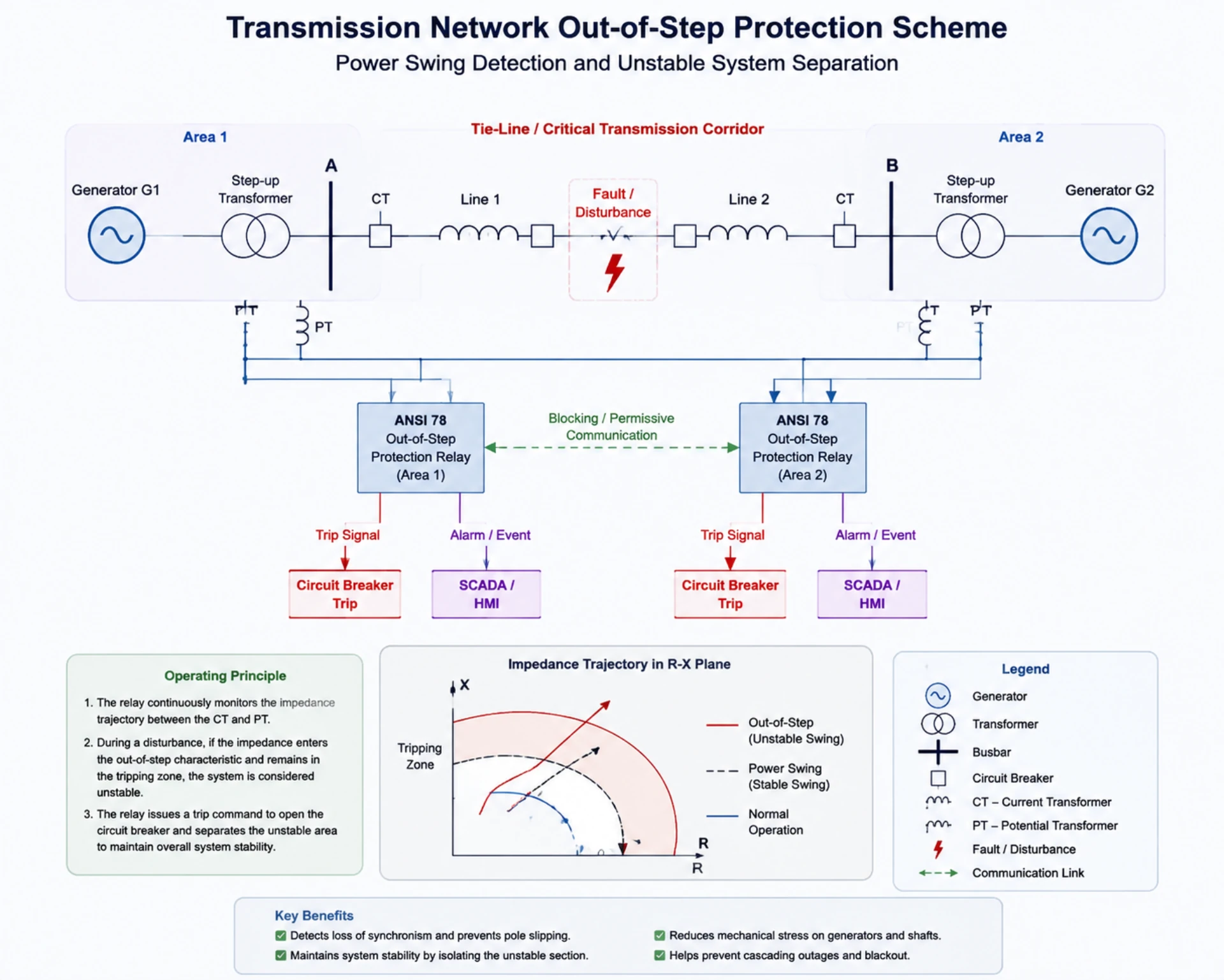
Out of Step Protection: ANSI 78 Principle, Settings and Applications
Out of step protection detects loss of synchronism between synchronous machines or grid areas and acts before the rotor loses pole lock. The function carries ANSI device number 78. It follows the impedance trajectory on the R-X plane, then trips, blocks or splits the network, depending on whether the swing can still recover.
Three outcomes, one measurement.
Fault protection clears a short circuit in tens of milliseconds; a swing runs for seconds. Overloads change current magnitude, not rotor position. A 78 element watches the angle between the internal machine voltage and the system behind it. That is why it sits apart from every other device in the panel, and why nuisance tripping during a recoverable swing is the failure mode engineers watch for first.
Device numbers fix the boundary. ANSI/IEEE C37.2-2022 assigns 78 to phase-angle measurement and loss of synchronism. IEC 60255-1:2022 sets the common requirements any measuring relay has to meet. Application and setting practice for machines sits in IEEE C37.102-2023, and the impedance element most 78 schemes borrow is specified in IEC 60255-121:2014.
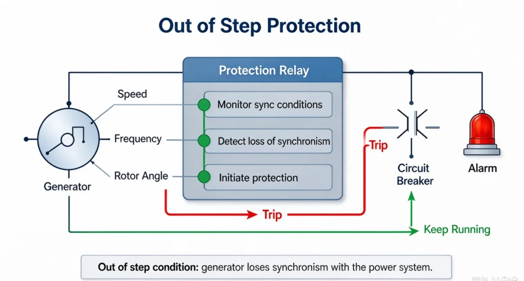
Out of Step Protection: At a Glance
- Device number: 78, assigned by ANSI/IEEE C37.2-2022 to loss of synchronism and pole slip protection
- Synchronous generator: trip before the first pole slip lands on the shaft; typically one slip
- Cross-compound set: two shafts on one trajectory, counted across both machines
- Tie line: block during a recoverable swing, split the network once the trajectory crosses both blinders
- Large motor or transformer feeder: applied where excitation failure or load rejection can open the rotor angle
- Detection input: apparent impedance on the R-X plane, plus the voltage-to-current phase angle
- Neighbouring codes: 21 distance, 40 loss of field, 50/51 overcurrent, 87 differential
- Outputs: trip, block, or controlled islanding, with a disturbance record for the post-mortem
The protected object decides everything downstream. A generator does not behave like a tie line, and neither behaves like an induction motor bank. Machine-side coverage belongs to the generator protection relay. Line-end coverage belongs to distance protection for transmission lines. Dedicated hardware for splitting a network lives in the 78 system separation protection device.
Four terms carry most of the argument:
- Synchronism: The consistent phase angle and frequency operation between generators and the power grid
- Rotor angle stability: The ability of synchronous units to maintain stable power output during system disturbances
- Loss of synchronism: Irreversible phase angle deviation between rotating equipment and the grid, also defined as pole slipping
- Pole slipping: Severe out-of-step failure that causes periodic power reversal and mechanical impact on generators
In engineering terms, the function is asked to do four things:
- Prevent mechanical burnout and shaft damage of synchronous generators and motors
- Block the spread of system oscillation and avoid regional power grid instability
- Split unstable grid sections to retain stable power supply areas
- Hold together whatever part of the network can still be supplied
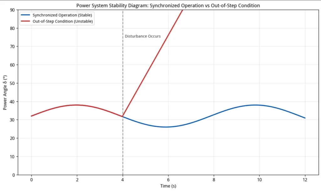
What Causes an Out of Step Condition?
Out-of-step failures do not occur randomly. They are triggered by specific system disturbances that break rotor angle balance. For EPC contractors and plant operation teams, mastering these causes is the premise of accurate out of step settings and parameter tuning.
Severe System Faults
High-impact grid faults are the most common inducement. Transmission line short circuits, transformer faults, and busbar faults cause instantaneous system voltage depression, reduce power transmission capacity, and lead to unbalanced generator rotor torque. The rotor accelerates rapidly, deviates from the synchronous state, and eventually causes loss of synchronism.
Large Power Transfer and Weak Grid Conditions
Long-distance power transmission, ultra-high power transfer levels, and low short-circuit capacity grids are highly susceptible to power oscillation. This scenario is frequent in new energy gathering areas and remote power plants, requiring settings derived from the actual transfer level rather than a default template.
Problems with motor excitation
Abnormal excitation systems directly damage generator synchronization stability, including AVR failure, full or partial loss of field, and improper excitation control. It is the primary internal cause behind a synchronous generator or a synchronous motor losing synchronism.
Sudden Load Changes
Large-scale motor startup, sudden load rejection, and adjacent generator tripping will instantly change system power balance, induce rotor angle oscillation, and trigger potential out-of-step risks.
Difference Between Power Swing and Out of Step Condition
One measurement, two verdicts.
Most engineers confuse a recoverable swing with a genuine loss of synchronism, and that confusion accounts for a large share of misoperations. Out of step protection operates only in the second column. Treating the first column as a fault is how whole regions lose supply over a swing the network would have ridden out. The following table separates the two conditions, which is where any setting study starts.
| Item | Power Swing | Out of Step |
|---|---|---|
| System condition | Stable, recoverable disturbance | Unstable, irreversible system state |
| Rotor angle variation | Fluctuates within a safe range and recovers automatically | Continues to increase without self-recovery |
| Protection action | Blocking protection to avoid false tripping | Active tripping and grid splitting |
| Core purpose | Ensure protection selectivity during normal oscillation | Eliminate unstable links and protect system safety |
A qualified relay must separate the two states cleanly: block on a recoverable swing, trip on a genuine loss of synchronism. Get this wrong and either the network splits unnecessarily or a machine takes the shock.
How the 78 Relay Tracks Stability
Two mechanisms. One question.
Both mechanisms below answer the same question from different inputs. A scheme on a machine leans on the impedance path, because the machine reactance is known. Out of step protection placed on a network usually leans on the measured angle, because the equivalents behind it keep changing. Both appear in generator relays and in line stability devices, and most relays shipped today run them together.
Impedance-Based Detection Principle
Read the R-X plane.
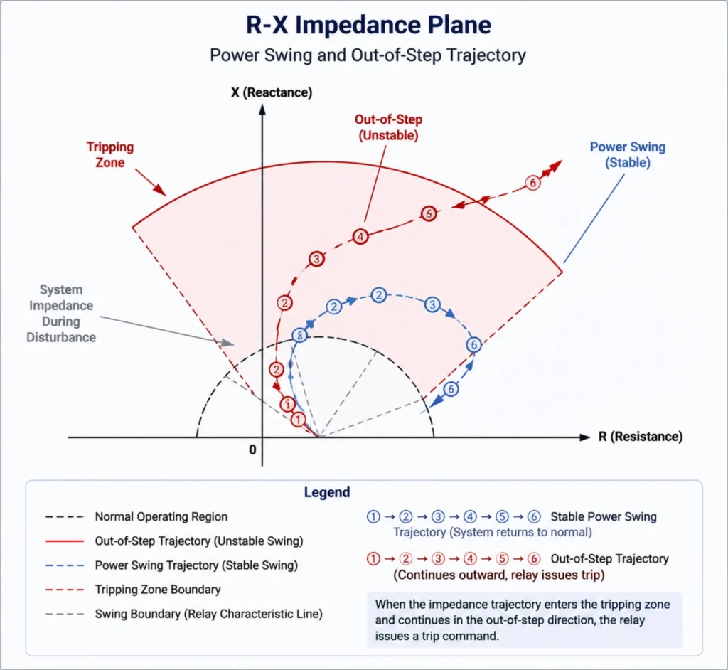
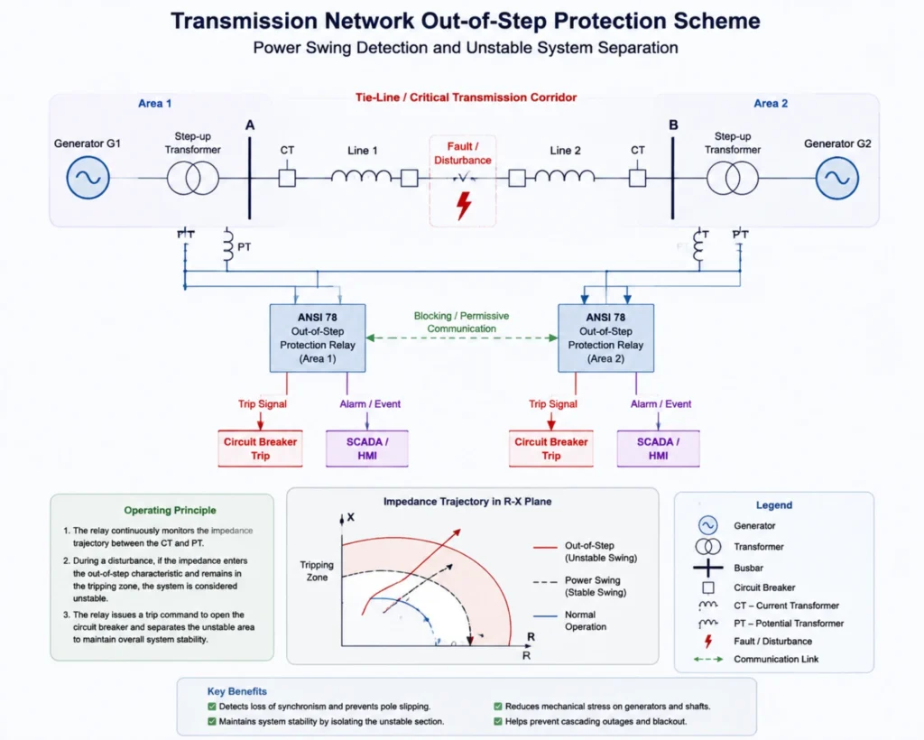
This is the most mainstream technical principle of ANSI 78 relay. The relay monitors the real-time system impedance trajectory on the R-X plane. Under normal operating conditions, the system impedance stays in a stable zone. When disturbance occurs, the impedance point moves continuously with power oscillation.
Two shaped elements define the zone. Blinders are parallel boundaries that cut across the R axis and mark where the trajectory enters and leaves; a lens or mho characteristic may sit between them. The relay times the crossing. A point that races through belongs to a fault. A point that crawls belongs to a swing. When it sits between the blinders longer than the timer allows, the swing has stopped recovering.
Slip cycles are the second clock. Each passage of the trajectory through the characteristic counts as one pole slip, and the resulting picket fence of pulses tells the relay whether this was a single recoverable swing or a machine that has lost rotor lock.
The relay judges system stability by analyzing the moving speed, direction, and residence time of the impedance trajectory. It distinguishes stable power swing from unstable out-of-step faults and outputs corresponding blocking or tripping commands. This principle is what cross-compound units rely on, where two shafts swing against each other instead of against the grid.
Voltage and Current Angle Measurement
Same answer, second input.
The protection device collects real-time voltage and current signals, calculates phase angle differences between system sides and rotating equipment, and tracks power flow reversal trends. When the phase angle exceeds the preset stable threshold and continues to diverge, the system is judged to be out of step, which holds for generators and for transmission lines alike.
ANSI 78 Out of Step Relay: Number, Scope and Functions
The number is easy. The scope is not.
The ANSI 78 out of step relay name comes from the device number itself. ANSI/IEEE C37.2-2022 assigns 78 to phase-angle measurement, which covers both the loss of synchronism and the pole slip end of the same problem.
One number, two duties. On a machine the relay protects the shaft. On a network it protects the interconnection. The hardware is often identical; the settings are not.
What Is ANSI 78 Protection?
Written into the device standard.
ANSI 78 relay is a dedicated stability protection device, independently responsible for system loss of synchronism detection and tripping control. It complements conventional fault protection and is widely deployed in thermal power, hydropower, new energy stations, and high-voltage transmission networks.
Main Functions of Out of Step Relay
Five duties in one element.
| Function | Engineering Description |
|---|---|
| Power swing detection | Real-time monitoring of system power oscillation amplitude and frequency |
| Out-of-step tripping | Trip circuit breakers to split unstable grid sections |
| Pole slip detection | Identify generator pole slipping faults to protect unit mechanical safety |
| Blocking logic | Prevent misoperation during stable power swing |
| Event recording | Record fault waveforms and action logs for post-analysis |
Where Each Scheme Is Applied
Object first, settings second.
Schemes divide by object. Generator-side protection answers mechanical questions. Transmission-side protection answers network questions. Both cover conventional units as well as cross-compound sets.
The Generator Scheme
Machines first.
A generator needs this function installed, whatever the rating: no grid-connected synchronous unit is exempt, and that includes cross-compound sets. Cross-compound machines have two shafts sharing one throw, so the calculation has to follow dual-unit oscillation rather than copy a single-shaft setting.
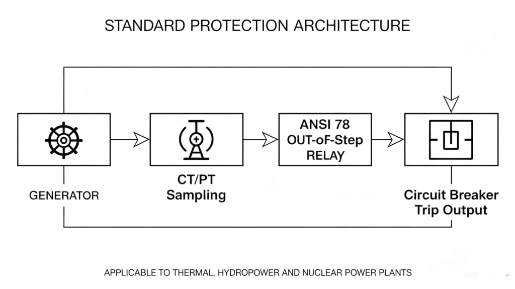
Standard protection architecture: Generator → CT/PT sampling → ANSI 78 relay → Circuit breaker trip output. It is universally applied in thermal, hydropower, and nuclear power plants.
The Tie-Line Scheme
Networks second.
Tie-line schemes hold together regional interconnections. When oscillation between two areas stops recovering, the relay splits the tie at a chosen point so both parts survive on their own generation.
Out of Step Protection Settings: Zones, Timers and Slip Counts
Three numbers decide it.
Out of step settings come down to three numbers: how large a zone the relay guards, how long it waits, and how many slips it tolerates. Everything else follows from the network study.
Impedance Zone Setting
Calculate based on system equivalent impedance, generator transient reactance, and transformer impedance. Ensure the protection zone covers all possible out-of-step oscillation trajectories while avoiding overlapping with fault protection zones.
Out-of-Step Timer Setting
Coordinate with system fault clearing time and stable swing duration. Reserve sufficient time for the system to recover spontaneously, and trigger tripping only when oscillation continues to deteriorate.
Number of Pole Slip Setting
Read the count off a duty chart. The mechanical tolerance of the shaft sets one bound, grid stability requirements set another, and a transient stability study reconciles them. Pole slip protection thresholds differ between a steam turbine, a hydro machine and a synchronous condenser, and each one is settled by its duty chart.
Testing and Commissioning
A setting sheet proves nothing on its own.
Strict testing and commissioning eliminate hidden dangers of protection refusal and misoperation, which is a key link for EPC project delivery and plant daily maintenance.
Protection Relay Testing
Test core indicators including relay pickup characteristics, action time accuracy, logic validity, and trip output reliability to verify how the 78 element itself responds.
Dynamic Simulation Test
Adopt real-time power system simulators to simulate stable swing, unstable oscillation, and pole slipping conditions, verifying the relay’s identification and action capability under actual working conditions.
Commissioning Checklist
| Test Item | Test Purpose |
|---|---|
| CT polarity test | Ensure accurate current sampling and avoid trajectory judgment deviation |
| PT wiring check | Verify voltage signal authenticity and stability |
| Relay setting verification | Confirm all calculation parameters match design requirements |
| Trip circuit test | Guarantee reliable breaker tripping output |
ANSI Code Map: 78 Against Neighbouring Functions
Different questions, same network.
Stability control is not fault protection, and the distinction decides how a panel is arranged. Each device below answers a different question about the same network. Only one of them watches the rotor angle. This is the map we hand over at scheme stage, before anyone commits to a wiring list.
| Protection Function | ANSI Code | Core Purpose |
|---|---|---|
| Differential Protection | 87 | Internal fault protection for generators and transformers |
| Distance Protection | 21 | Line short-circuit fault protection |
| Overcurrent Protection | 50/51 | Overcurrent and short-circuit backup protection |
| Out of Step Protection | 78 | Power system stability and loss of synchronism protection |
| Loss of Field Protection | 40 | Generator excitation failure protection |
Typical Applications
Where it earns its keep.
Power Plants
Every grid-connected synchronous machine carries the 78 element: conventional generators, synchronous motors used as compensators, and cross-compound sets. The reason is mechanical, not electrical. A slipping pole twists the shaft and pumps the foundation.
High Voltage Transmission Networks
At 110 kV, 220 kV and 500 kV, tie-line schemes provide regional stability control. The tripping point is chosen during planning, not during commissioning, because the split has to leave both islands with enough generation.
Renewable Energy and Modern Grids
For weak grids with high renewable energy penetration, out-of-step protection compensates for insufficient system inertia, which is where swing damping on a weak grid earns its keep.
How to Select a Relay Supplier
Hardware is easy to buy.
For EPC projects and power plant owners, relay reliability determines long-term grid operation safety. Professional suppliers provide standardized products and full-cycle technical services.
Core Supplier Evaluation Factors
- Standard compliance: Declared conformance to IEC 60255-1:2022 and device numbers to ANSI/IEEE C37.2-2022
- Algorithm performance: Mature impedance trajectory identification algorithm, accurate distinction between swing and out-of-step faults
- Testing capability: FAT with injected swing trajectories, not just steady-state pickup checks
- Engineering experience: Rich project cases in generator and transmission line stability protection
- Technical support: Provide on-site commissioning, parameter setting, and after-sales technical guidance
Standard Relay Supply Process
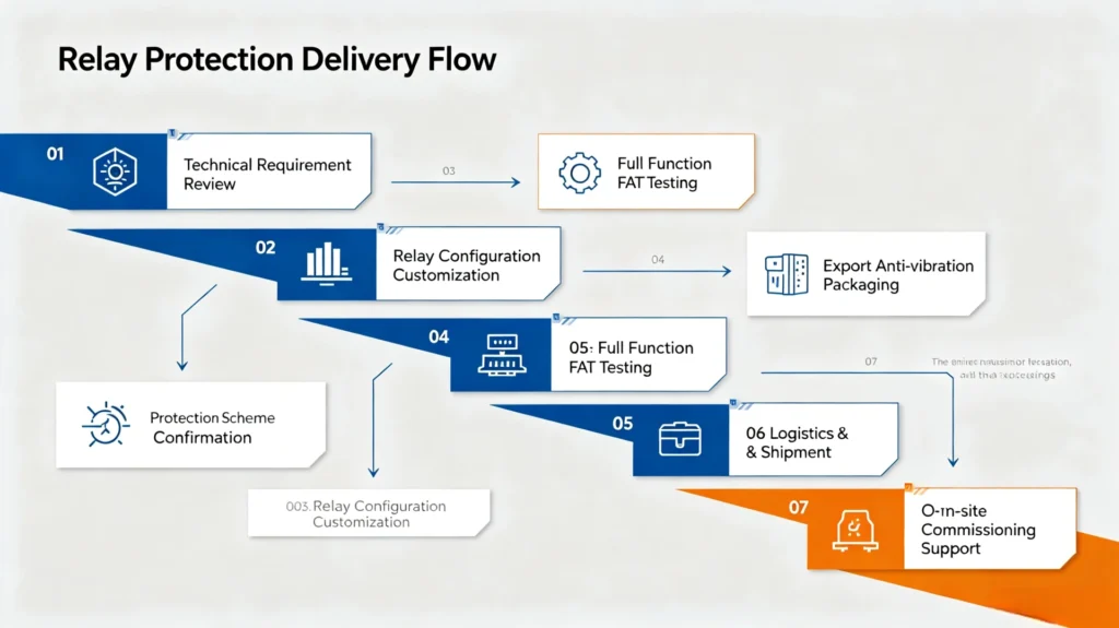
Technical Requirement Review → Protection Scheme Confirmation → Relay Configuration Customization → Full Function FAT Testing → Export Anti-vibration Packaging → Logistics & Shipment → On-site Commissioning Support
Frequently Asked Questions
Short answers, straight from site.
Q1: What is the purpose of out of step protection?
A1: It detects power system loss of synchronism, distinguishes stable power swing from unstable out-of-step faults, executes targeted tripping or blocking actions, protects generator equipment, and maintains grid stability.
Q2: What is ANSI 78 relay used for?
A2: ANSI 78 is the standard device code for out-of-step and pole slip relays, applied to generator and transmission line stability protection to solve system loss of synchronism faults.
Q3: What is the difference between power swing and out of step?
A3: Power swing is a stable, recoverable system oscillation requiring protection blocking; out-of-step is an unstable, irreversible fault requiring immediate tripping and grid splitting.
Q4: How does an out-of-step relay detect instability?
A4: It tracks system impedance trajectory and voltage-current phase angle changes, judges oscillation stability through moving speed and duration, and identifies out-of-step faults accurately.
Q5: Where is out of step protection applied?
A5: It covers synchronous generators, synchronous motors, cross-compound units, and high-voltage transmission lines, applicable to thermal, hydropower, new energy power plants and regional power grids.
Q6: What are blinders and why do I need two of them?
A6: Blinders are two parallel boundaries drawn across the R axis. The relay measures how long the impedance point takes to travel from one to the other. A crossing measured in milliseconds is a fault; one measured in hundreds of milliseconds is a swing. Two blinders give the relay a start and a stop, which is all a timer needs.
Q7: How many pole slips should trip a generator?
A7: Most machines are set to trip on the first slip, because the shaft torque peak arrives with it. A hydro unit with generous inertia may be allowed two. The number is not a preference; it comes from the mechanical duty chart the manufacturer issues for that rotor.
Q8: Can a distance relay replace device 78?
A8: Not completely. A distance relay sees impedance and some models include a swing-blocking or out-of-step trip element, so a 21 device can carry part of the duty on a line. Machines are different: a dedicated 78 function tracks picket-fence slip cycles and shaft duty that no distance element models.
Q9: Is system separation the same thing?
A9: No. Detection answers “has synchronism been lost”. System separation answers “where do we cut”. A 78 relay can issue both commands, but the splitting point is a planning decision taken from load-flow studies, and it usually sits with a dedicated system separation protection scheme.
Related Reading
The 78 element rarely sits alone in a panel. These eight pages cover what runs beside it, what gets confused with it, and what splits the network after it decides.
- Generator protection relay: the full function set around a synchronous machine
- Loss of excitation protection (ANSI 40): the condition most often confused with loss of synchronism
- Distance protection for transmission lines: how the 21 element blocks during a swing
- ANSI code protection relay: device numbers and what each one covers
- 78 system separation protection: dedicated hardware for controlled islanding
- Frequency relay protection: the other half of an islanding decision
- Protection relay testing: how to inject a swing trajectory at FAT
- Hydropower relay protection: machine schemes where inertia is low
Conclusion
Losing synchronism is not a fault that clears itself. It is a condition that either settles or spreads, and the difference appears on the R-X plane well before it appears on the shaft. Reading that difference is the whole job of device 78.
Send us the single-line diagram, the CT and VT ratios, machine reactances and the protocol list. We return a function matrix, a setting sheet carrying the blinder positions and slip-count values, and the I/O list. That is usually enough to settle transmission line protection panels before anything is built.
Technical References & Data Sources
Six sources carry every claim on this page. Two set device definitions, two set product and test requirements, one is a Chinese national code, and one is a peer-reviewed review of swing detection methods.
| Source | What it covers | Type | Edition |
|---|---|---|---|
| ANSI/IEEE C37.2-2022 | Electrical power system device function numbers, acronyms and contact designations; assigns 78 to phase-angle measurement | Standard | 2022 |
| IEC 60255-1:2022 | Common requirements for measuring relays and protection equipment | Standard | 2022 |
| IEEE C37.102-2023 | Guide for AC generator protection, including loss-of-field and out-of-step application | Guide | 2023 |
| IEC 60255-121:2014 | Functional requirements for distance protection, the impedance element most 78 schemes borrow | Standard | 2014 |
| GB/T 14285-2006 | Technical specification for relay protection and automatic devices in Chinese power systems | National code | 2006 |
| International Journal of Electrical Power & Energy Systems, Out-of-step protection fundamentals and advancements | Peer-reviewed review of swing detection | Journal | See publisher |



About Author

Hello, I'm Leno Zhang. I have 15 years of experience in the power relay protection industry with extensive pre-sales and after-sales project experience. Our company specializes in various complete sets of relay protection and automation equipment. I can assist customers in solving all practical on-site project challenges and provide optimal integrated solutions.
Tell Us Your Requirement
High Quality
Stable performance, reliable design, ensuring safe operation for power system protection and grid stability.
Fast Delivery
Timely delivery to support your urgent orders and project schedules efficiently and professionally at any time.
Best Warranty
Professional Warranty: Reliable after-sales support for stable relay protection and long-term customer satisfaction.