

-
Leon Zhang sales consultant
-
Email: zxl635973785@gmail.com
-
Phone/WhatsApp: +86 13655813266
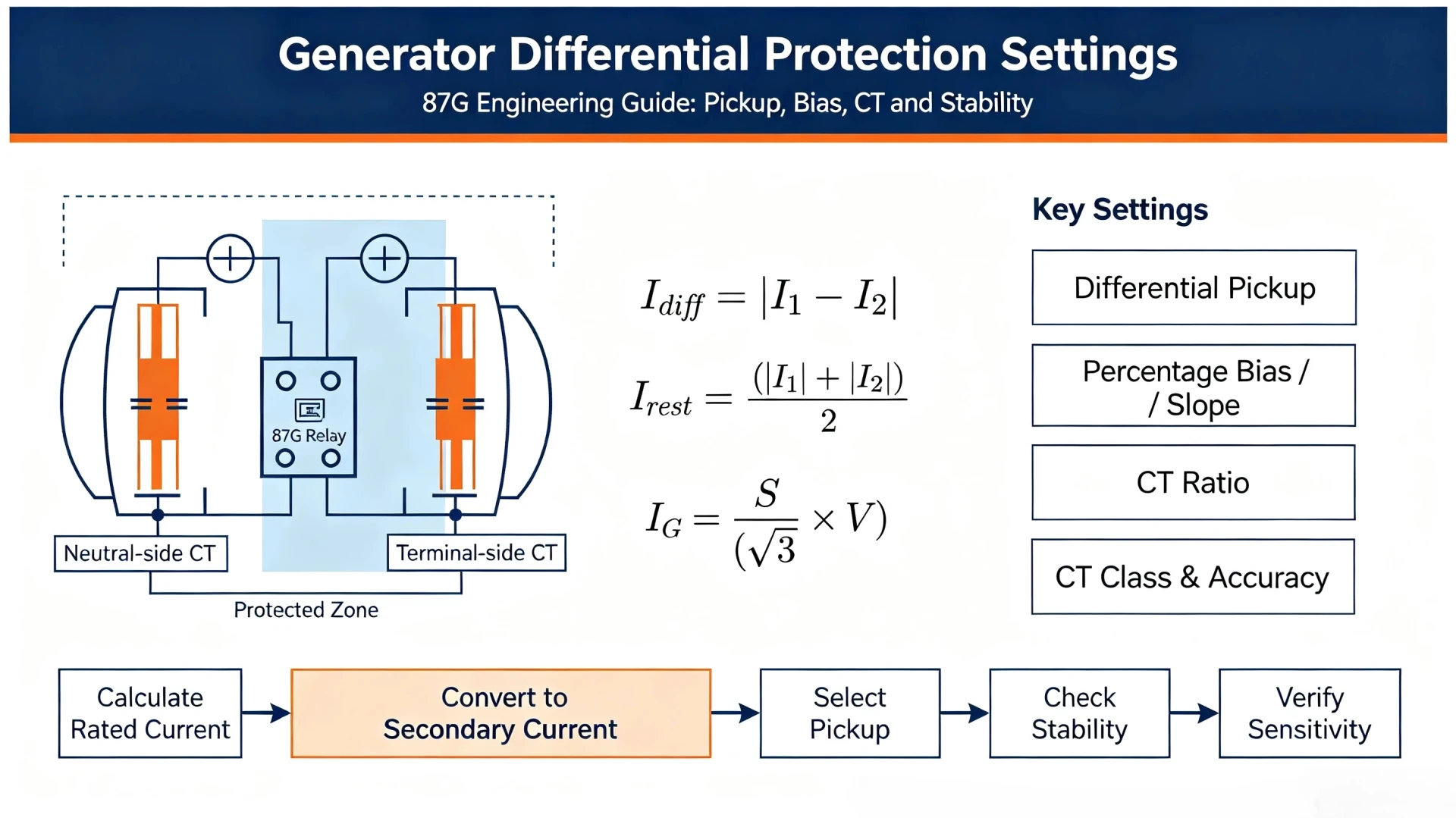
Generator Differential Protection Settings: Pickup, Bias, CT and Stability
Introduction
Generator differential protection (ANSI 87G) is the primary protection for detecting internal short‑circuit faults within generator stator windings. Many field engineers treat this protection as a simple threshold setting task, but improper parameter configuration remains one of the top root causes for generator protection mis‑operation.
Setting 87G differential relays requires iterative engineering judgement rather than applying universal fixed values. Every final setting must balance internal‑fault sensitivity and external‑fault stability.
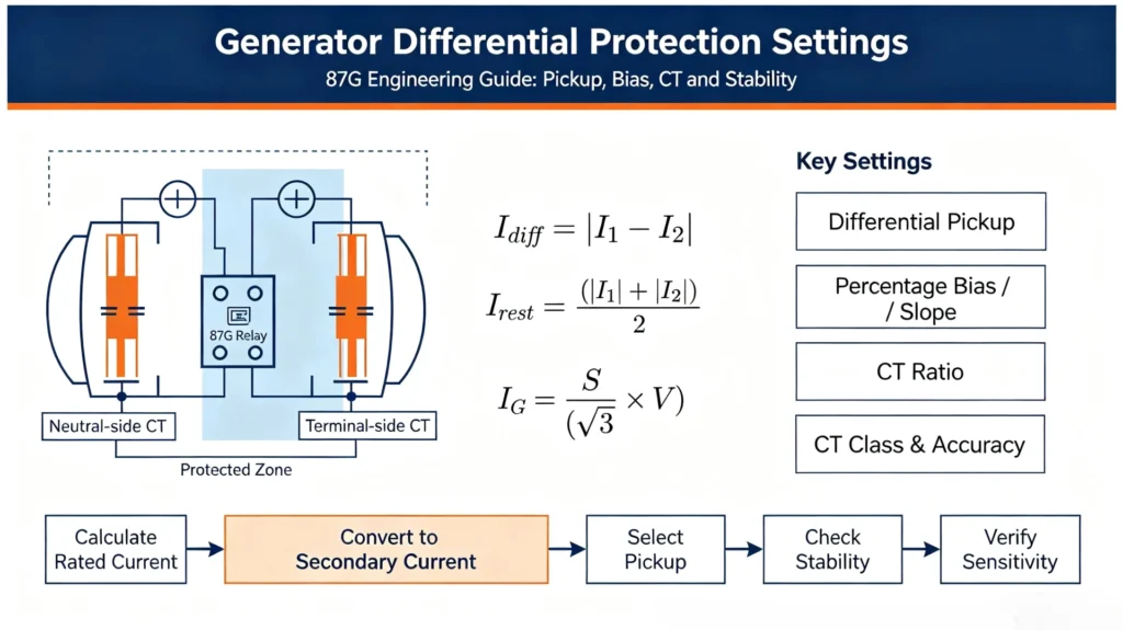
Several core variables govern the complete setting workflow: generator rated current, CT ratio, CT accuracy class, CT saturation performance, differential current, restraint current, percentage bias (slope), minimum differential pickup, through‑fault magnitude and relay internal algorithm.
Poorly configured 87G settings lead to three common field outcomes:
- Failure to trip: The relay cannot detect low‑magnitude internal stator faults.
- Nuisance tripping: Unwanted trips occur during heavy external through‑fault events.
- CT‑saturation‑driven maloperation: False differential current created by saturated current transformers triggers spurious relay operation.
Key Takeaways Generator differential protection settings are primarily determined by the generator rated current, CT ratio, differential pickup, percentage bias or slope, and the required stability against external faults. The settings must provide sufficient sensitivity for internal stator faults while remaining stable during through‑fault conditions and CT saturation. Setting values cannot be copied blindly across different generator‑CT combinations; all parameters require calculation and on‑site verification.
What Is Generator Differential Protection?
This section covers core working principles only, without redundant introductory descriptions of generator hardware.
Protection Principle
Generator differential protection applies Kirchhoff’s Current Law. It compares the current entering the protected generator winding against the current leaving the winding.
Differential current formula: Idiff=∣I1−I2∣
- Healthy operating condition: I1 and I2 are nearly identical. Theoretical differential current sits close to zero. Minor non‑zero values come from CT mismatch, measurement tolerance and wiring errors.
- External through‑fault: Large fault currents flow through the generator. Primary currents on both sides still match. The relay must stay stable even if CT errors rise.
- Internal stator fault: Current balance inside the protected zone breaks. A substantial genuine differential current appears, triggering relay trip output.
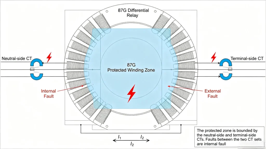
Generator Differential Protection Zone
(Suggested diagram: Generator Differential Protection Zone Diagram) Diagram elements to include:
- Generator stator winding
- Neutral‑side CT set
- Terminal‑side CT set
- 87G differential relay
- Clear boundary for the protected winding zone
- Markers for internal fault (inside zone) and external fault (outside zone)
Generator Differential Protection Settings: Main Parameters
Every setting parameter serves a distinct engineering purpose. The table below summarises critical parameters for ANSI 87G generator differential relays.
| Setting Parameter | Core Purpose |
|---|---|
| Differential Pickup | Defines the minimum differential current magnitude required to initiate relay operation |
| Percentage Bias / Slope | Suppresses false operation under external faults by raising the operating threshold proportionally to restraint current |
| Restraint Current | Reflects the magnitude of through‑fault load current and generates the restraining bias effect |
| CT Ratio | Scales primary generator current down to secondary current levels compatible with relay analogue inputs |
| CT Class / Accuracy | Directly impacts measurement error, CT saturation onset and overall differential‑scheme stability |
| High‑Set Differential | Delivers instantaneous fast tripping for severe high‑magnitude internal generator faults |
| Operating Time | Sets intentional time delay; most 87G applications use instantaneous trip for internal faults |
| CT Saturation Compensation | Relay‑internal algorithm to mitigate false differential signals caused by saturated CTs |
How to Calculate Generator Differential Protection Pickup Setting
Differential pickup is the base threshold of 87G protection. In generator differential protection calculation, engineers cannot select pickup values from generic tables; calculation must start from actual generator and CT nameplate data..
Step 1 — Calculate Generator Rated Primary Current
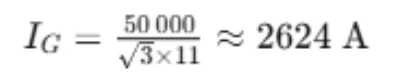
The generator rated phase current is calculated from generator apparent power and line‑to‑line rated voltage.
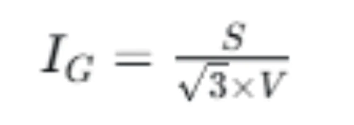
Where:
- S= Generator rated apparent power (kVA or MVA)
- V = Generator rated line‑to‑line voltage (kV)
- IG = Generator rated phase primary current (A)
Field calculation example: 50 MVA, 11 kV synchronous generator

Practical note: This rated current value is only an input for subsequent relay setting. You cannot directly assign this calculated value as your final differential pickup. CT ratio, relay input rating, CT mismatch and overall protection scheme all modify the final pickup setting.
Step 2 — Convert Generator Rated Current to Relay Secondary Current
Relay analogue inputs receive CT secondary current. Convert primary generator rated current into secondary side values with the selected CT transformation ratio.
Formula for secondary rated current:
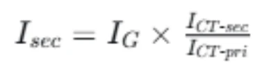
Using the previous generator example: Generator rated primary current = 2624 A CT ratio: 3000 / 5 A

Critical field reminder: Confirm whether your differential relay accepts setting values entered as primary current or secondary current. Relay manufacturers implement setting interfaces differently. Misinterpreting primary‑secondary scaling is a frequent commissioning mistake.
Step 3 — Select Differential Pickup Value
The differential pickup threshold must satisfy two conflicting engineering targets:
- Sufficient sensitivity to detect low‑current internal stator faults.
- High enough threshold to avoid operation caused by steady‑state measurement imperfections.
Factors you must evaluate during pickup selection:
- Maximum normal generator load current
- Ratio mismatch between neutral‑side CTs and terminal‑side CTs
- Relay analogue‑channel measurement error
- CT magnetizing‑current offset
- Potential wiring‑induced imbalance
- Minimum internal‑fault current expected inside generator windings
Important engineering principle: There exists no universal percentage pickup value applicable for all generator projects. Every project needs assessment of its unique CT performance and fault level data.
Percentage Bias / Slope Settings for Generator Differential Protection
Percentage bias (also called slope) is the core mechanism that keeps 87G relays stable during heavy external through‑fault events.
Why Percentage Bias Is Required
When an external fault occurs outside the generator differential protected zone:
- Large through‑fault current flows through terminal‑side and neutral‑side CTs.
- High primary fault current pushes CTs toward saturation.
- Once CT saturation starts, secondary‑side current output distorts.
- Even though the actual primary currents are balanced, distorted secondary currents produce artificial differential current.
Without percentage‑bias logic, this false differential signal will cause nuisance generator trips. Percentage‑restraint characteristics raise the relay operating threshold as restraint current increases.
Differential Current and Restraint Current
The most widely adopted definitions for generator differential protection:
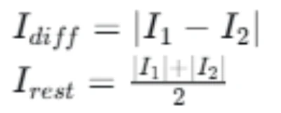
Typical relay operating boundary formula:

Key note for EPC engineers: The exact operating formula varies across relay manufacturers. Some vendors use full‑sum restraint current instead of the average‑value formula shown above. Always cross‑reference against your relay’s official technical manual before finalising settings.
How to Select the Differential Protection Slope
Slope selection is an engineering trade‑off between fault sensitivity and external‑fault stability.
Factors Affecting Slope Selection
The following parameters drive slope selection decisions:
- CT saturation performance under maximum external through‑fault current
- Ratio and magnetizing mismatch between neutral‑side and terminal‑side CT sets
- CT accuracy class and knee‑point voltage
- Maximum through‑fault current magnitude (system fault level at generator terminals)
- Generator fault contribution
- CT secondary loop burden (including cable lead resistance)
- Embedded differential algorithm implemented inside the chosen relay
Low Slope vs High Slope Trade‑Off
| Slope Setting | Typical Behaviour | Engineering Trade‑Off |
|---|---|---|
| Lower slope | Higher sensitivity for small internal faults | Less tolerance for CT measurement error and CT saturation risk during external faults |
| Higher slope | Strong external‑fault stability; resists CT‑saturation‑driven false differential signals | May reduce sensitivity for low‑magnitude internal stator faults |
Practical field tip: Avoid selecting an excessively high slope purely to chase stability. Always cross‑check internal‑fault sensitivity after you finalise slope parameters.
How CT Configuration Affects Generator Differential Protection Settings
CT hardware configuration directly shapes all 87G relay setting values. This article treats CT parameters as calculation inputs; full CT selection and wiring guidance can be found in our dedicated technical article Generator Differential Protection CT Configuration.
Terminal‑Side and Neutral‑Side CTs
Generator differential protection requires matched CT sets installed at the generator terminal side and generator neutral side. The physical placement of these two CT pairs defines the complete differential protection zone.
Mismatch between terminal‑side and neutral‑side CT performance creates steady‑state differential offset, which must be accommodated within your pickup and slope setting.
CT Ratio Selection
CT ratio selection must satisfy multiple constraints:
- CT primary rating should cover generator full‑load rated current
- CT secondary output must fit the relay analogue‑input range
- CT thermal short‑time rating must withstand maximum expected through‑fault duration
- CT saturation performance under maximum external fault must be validated
CT Class and Accuracy
CT ratio alone is insufficient to guarantee reliable 87G operation. Engineers need to evaluate:
- CT accuracy class (for protection‑grade CTs, class 5P / 10P are common choices)
- Knee‑point saturation voltage
- CT excitation characteristic curves
- Total connected secondary burden including wiring resistance and relay input burden
Poor CT performance cannot be fully compensated by relay‑side pickup and slope adjustments. Even well‑tuned relay settings will fail if CT hardware is underspecified.
CT Saturation and Generator Differential Protection Stability
CT saturation remains the leading cause of unexpected 87G differential relay operation during external faults.
Why CT Saturation Creates False Differential Current
For ideal matched CTs during external fault conditions: I1=I2
When one set of CTs enters saturation under high through‑fault current, secondary‑side output becomes distorted:
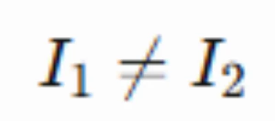
This imbalance creates non‑zero artificial differential current:Idiff>0
. The relay interprets this signal as an internal fault unless bias‑restraint logic suppresses mis‑operation.
How Bias Helps Maintain Stability
Percentage bias raises the relay operating threshold proportionally to measured restraint current. When through‑fault current rises and CT saturation begins, the operating boundary increases to filter out saturation‑induced false differential signals.
Bias is mitigation, not a complete fix. Severe deep CT saturation can still cause mis‑operation even with high slope values.
External Fault Stability Check Workflow
Use this step‑by‑step engineering check for every generator differential setting project:
- Calculate maximum expected through‑fault primary current.
- Convert fault current into CT secondary‑side magnitude.
- Assess expected CT saturation level under this fault condition, using CT excitation curve data.
- Estimate resulting false differential‑current magnitude.
- Compare estimated false differential signal against relay bias operating characteristic.
- Confirm relay remains stable under this fault scenario.
Suggested visual: Flowchart for external fault stability assessment.
Generator Differential Protection Settings Example
This practical generator differential protection calculation example follows industry field workflow for a 50 MVA, 11 kV synchronous generator.
| Parameter | Example Project Value |
|---|---|
| Generator rated power | 50 MVA |
| Generator line‑line voltage | 11 kV |
| Generator rated primary current | 2624 A |
| Installed CT ratio | 3000 / 5 A |
| Rated CT secondary current at full generator load | 4.37 A |
| Differential pickup | Relay‑dependent (requires CT‑mismatch assessment) |
| Bias slope setting | Relay‑dependent (requires external‑fault stability check) |
Step 1: Compute generator rated primary phase current
Step 2: Convert rated current to CT secondary side

Step 3: Establish preliminary differential pickup
- Check the allowable setting range of your selected differential relay.
- Evaluate expected CT ratio and magnetizing mismatch between neutral‑side and terminal‑side CTs.
- Confirm minimum internal‑fault current magnitude for stator winding short‑circuit events.
- Refer to the relay manufacturer’s application recommendations for generator differential schemes.
Do not finalise pickup solely by calculation. Move forward to stability and sensitivity validation steps.
Step 4: Evaluate bias‑slope characteristic Simulate maximum external through‑fault conditions. Verify that saturation‑driven false differential signals will sit below the relay biased operating boundary.
Step 5: Validate internal‑fault sensitivity Simulate minimum expected internal stator‑fault differential current. Confirm:
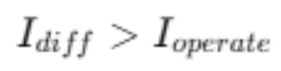
Ensure genuine internal faults will reliably drive the relay to trip.
Generator Differential Protection Settings for Different Generator Applications
Different generator types do not come with pre‑assigned fixed 87G setting values. Adjustments originate from system‑level hardware differences.
Synchronous Generator
Standard synchronous generator units (turbogenerators and hydrogenerators) follow the core calculation workflow laid out above. Key variables include generator grounding arrangement, neutral CT installation feasibility and system fault level.
Hydrogenerator
Hydro units often feature larger stator winding physical dimensions and different neutral‑grounding configurations. Engineers must pay extra attention to minimum internal‑fault current levels.
Turbogenerator
Large turbogenerators operate with high through‑fault current magnitudes. CT saturation assessment and external‑fault stability checks become especially critical.
Large Industrial Generator
Captive industrial generators often connect to weak utility grids. System fault levels may be lower than utility‑owned generator plants, which changes slope‑setting requirements.
General rule: Generator physical size, winding configuration, CT layout, neutral‑grounding method and system fault capacity all change optimal differential protection parameters. Never copy‑paste settings between different generator assets.
How to Verify Generator Differential Protection Settings
Calculated settings on paper are not sufficient for commissioning. Multi‑layer verification is mandatory to reduce on‑site operational risk.
Setting Calculation Review
Complete a formal setting‑calculation checklist before applying parameters to relay hardware:
- Generator nameplate power and voltage data
- Neutral‑side and terminal‑side CT ratio, accuracy class, knee‑point voltage and burden values
- Relay analogue‑input rating
- Selected differential pickup value
- Selected percentage bias / slope value
- Complete trip‑logic matrix including trip outputs and alarm assignments
Secondary Injection Test
Secondary injection is the standard bench‑level verification for differential relay behaviour. Inject analogue secondary‑side signals directly into relay terminals to test:
- Differential pickup threshold
- Full percentage‑bias operating characteristic curve
- Trip operating time
- Associated alarm logic
- Binary output contact behaviour
Note: Secondary injection validates relay algorithm performance. It cannot validate CT wiring, CT polarity or the complete primary‑side CT circuit.
Primary Injection / End‑to‑End Testing
Primary injection testing injects current on the primary side of installed CTs. This test verifies the complete physical loop including CT transformation performance, wiring polarity and cabling. This test is highly recommended for new generator commissioning.
External Fault Stability Test
Where site conditions permit, simulate or evaluate external through‑fault scenarios. Confirm the differential relay will not assert trip signals for faults outside the generator protected zone.
Common Generator Differential Protection Setting Problems
Field issues are grouped into problem description, root cause, consequence and practical inspection guidance.
| Problem | Root Cause | Consequence | Recommended Inspection |
|---|---|---|---|
| Pickup setting too high | Over‑compensation for CT mismatch; copied settings from other projects | Reduced sensitivity; risk of missing low‑magnitude internal stator faults | Recalculate minimum expected internal fault differential current; re‑evaluate CT mismatch magnitude |
| Pickup setting too low | Minimal consideration of CT measurement offset and magnetizing current | Elevated risk of nuisance tripping under load transients or external faults | Review CT excitation data; perform secondary injection test to check operating threshold |
| Incorrect CT ratio programmed into relay | Typographical error during setting entry | Incorrect scaling of differential and restraint current readings | Cross‑check relay CT‑ratio parameter against physical CT nameplate markings |
| Incorrect CT polarity | Wrong polarity wiring at CT terminals or relay analogue inputs | Large false differential current even under normal generator load | Perform end‑to‑end primary injection test; inspect CT wiring drawings |
| Insufficient CT performance | Undersized CT knee‑point voltage or excessive secondary burden | Severe CT saturation under external fault conditions; false differential signals | Re‑calculate total CT secondary burden; review CT excitation curve data |
| Improper bias / slope selection | Slope set too low ignoring system fault level; slope set excessively high without sensitivity check | Either nuisance tripping or degraded internal‑fault sensitivity | Re‑run external‑fault stability calculation together with internal‑fault sensitivity validation |
| Ignoring external‑fault stability check | Settings derived only from internal‑fault sensitivity perspective | Relay mis‑operation during system through‑fault events | Add formal external‑fault stability assessment as mandatory step in setting workflow |
Generator Differential Protection vs Other Generator Protection Settings
87G generator differential protection handles stator internal phase faults only. It is one component within the full generator protection suite.
| ANSI Function | Protection Purpose |
|---|---|
| 87G | Generator stator winding internal phase‑fault differential protection |
| 50 / 51 | Generator phase over‑current backup protection |
| 50N / 51N | Generator neutral over‑current ground‑fault protection |
| 64G | Stator 100 % ground‑fault protection |
| 46 | Negative‑sequence protection for unbalanced loading and phase faults |
| 40 | Loss‑of‑excitation protection |
| 32 | Reverse‑power protection (anti‑motoring) |
| 27 / 59 | Under‑voltage and over‑voltage protection |
Important note: Generator differential protection cannot replace these complementary protection functions. A reliable generator protection system must deploy a coordinated multi‑function protection scheme.
Practical Workflow for Generator Differential Protection Settings
Use this step‑wise workflow for real‑world EPC and utility generator‑protection commissioning:
- Collect complete generator nameplate data, CT nameplate information and system fault‑level data.
- Calculate generator rated primary current.
- Review CT ratio, accuracy class, knee‑point voltage and total secondary burden.
- Select preliminary differential pickup setting.
- Configure percentage bias / slope parameters.
- Run external‑fault stability assessment.
- Verify internal‑fault sensitivity performance.
- Configure complete trip‑logic and alarm assignments.
- Execute secondary‑injection relay testing.
- Complete primary‑side end‑to‑end testing where site conditions allow.
- Carry out site commissioning and final setting‑document hand‑over.
Frequently Asked Questions
What is generator differential protection setting?
Generator differential protection settings are the configured threshold and characteristic parameters inside an ANSI 87G differential relay. These parameters define at which magnitude of differential current the relay will issue trip outputs for generator internal stator faults, while remaining stable for external through‑fault events and CT measurement imperfections.
How do you calculate generator differential protection pickup?
Start with generator rated primary‑current calculation from MVA and kV nameplate values. Convert primary current to CT secondary side. After that, evaluate CT mismatch, CT magnetizing offset, relay measurement error and minimum expected internal‑fault differential‑current magnitude to derive preliminary pickup value. Final pickup must pass stability and sensitivity validation.
What is the typical percentage bias for generator differential protection?
There is no universal fixed bias value. Slope selection depends on CT saturation characteristics, maximum external through‑fault current, CT secondary burden and relay internal algorithm. Engineers must always refer to relay manufacturer application guidance alongside project‑specific CT and system data.
What is the difference between differential current and restraint current?
Differential current (Idiff) represents the current imbalance between the terminal‑side and neutral‑side CT circuits, which signals internal generator faults. Restraint current (Irest) reflects the magnitude of through‑fault load current. Restraint current generates the percentage‑bias restraining effect to avoid nuisance trips.
How does CT saturation affect generator differential protection?
CT saturation distorts secondary‑side current output under high fault current. Even with balanced primary‑side currents, saturation creates artificial differential current. Percentage bias can mitigate this risk, but hardware‑level CT over‑specification is the preferred first‑line engineering solution.
How do you test generator differential protection settings?
Two core test categories are applied: secondary injection tests verify relay algorithm, pickup threshold and bias curves. Primary‑side end‑to‑end injection testing validates complete CT circuits, CT polarity and installed wiring performance. Both test types are recommended for new generator commissioning.
What CT ratio is required for generator differential protection?
CT primary rating should cover generator full‑load rated current. CT secondary rating is normally 5 A or 1 A matching relay analogue‑input hardware. CT ratio alone is not sufficient; knee‑point voltage, accuracy class and secondary burden must also satisfy through‑fault performance requirements.
Why does generator differential protection trip during an external fault?
The most frequent root cause is CT saturation producing false differential signals. Additional possible causes include wrong CT polarity, excessive CT secondary burden, incorrectly low bias‑slope setting or incorrectly programmed CT ratio parameters inside the relay.
Conclusion
Generator differential protection setting work cannot rely on copied‑from‑project‑to‑project fixed parameters. Three groups of variables dominate final settings: generator rated electrical parameters, installed CT hardware performance, and relay‑internal differential algorithms.
- Differential pickup establishes the baseline sensitivity for detecting internal stator winding faults.
- Percentage bias or slope delivers external‑fault stability and filters false differential signals caused by CT mismatch and CT saturation.
- All calculated settings require multi‑stage verification: paper calculation review, secondary‑injection bench testing, and primary‑side end‑to‑end testing for new installations.
For generator protection projects, select differential relays based on generator rating, installed CT configuration, required protection functions, site communication requirements and commissioning constraints. Our generator‑differential protection relay hardware is engineered for utility‑scale generator assets and EPC project deployments worldwide.
Reference Technical Documents & Data Sources
- IEC 60255‑12: Measuring relays and protection equipment — Differential protection for generators and transformers
- ANSI / IEEE C37.102: Guide for AC Generator Protection
- IEEE C37.110: Guide for the Application of Current Transformers Used for Protective Relaying Purposes
- Manufacturer application manuals for generator differential protection relays
- CT excitation characteristic curve data sheets from current‑transformer vendors
- Utility and EPC standard generator‑protection setting calculation templates



About Author

Hello, I'm Leno Zhang. I have 15 years of experience in the power relay protection industry with extensive pre-sales and after-sales project experience. Our company specializes in various complete sets of relay protection and automation equipment. I can assist customers in solving all practical on-site project challenges and provide optimal integrated solutions.
Tell Us Your Requirement
High Quality
Stable performance, reliable design, ensuring safe operation for power system protection and grid stability.
Fast Delivery
Timely delivery to support your urgent orders and project schedules efficiently and professionally at any time.
Best Warranty
Professional Warranty: Reliable after-sales support for stable relay protection and long-term customer satisfaction.