

-
Leon Zhang sales consultant
-
Email: zxl635973785@gmail.com
-
Phone/WhatsApp: +86 13655813266
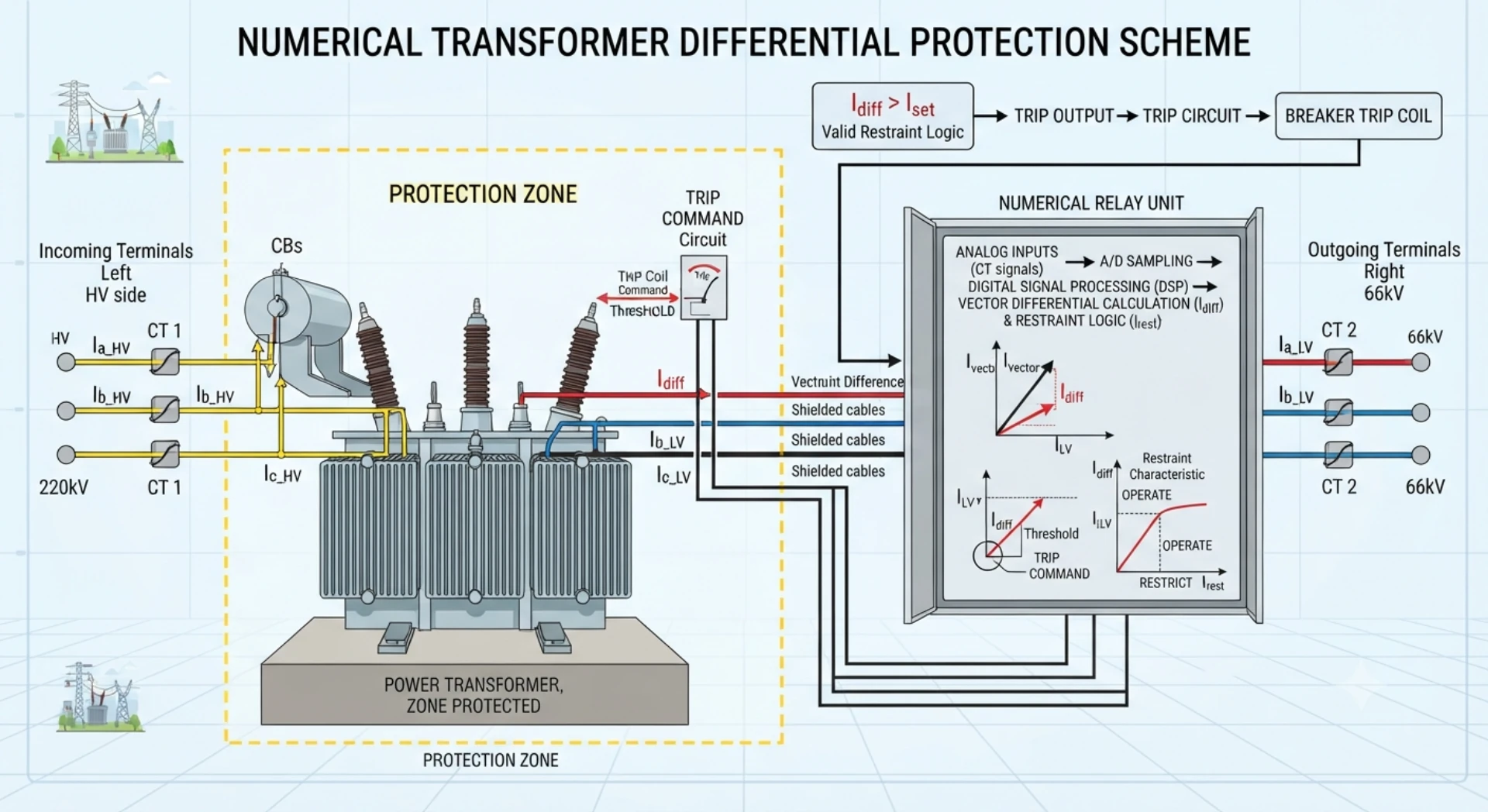
Numerical Transformer Differential Protection: How Digital 87T Relays Work
Introduction
Numerical transformer differential protection is a microprocessor-based protection method used to detect faults within the defined protection zone of a power transformer. Unlike conventional electromechanical differential schemes, a numerical 87T relay can digitally process CT inputs, compensate for transformer ratio and vector group effects, and apply percentage-bias and harmonic restraint algorithms.
Modern numerical transformer differential relays can also integrate event recording, fault oscillography, communication protocols and additional protection functions in a single device. These features make numerical 87T protection suitable for utility substations, industrial power systems, renewable energy plants and transformer retrofit projects.
This guide explains the architecture, operating principle, compensation functions, protection algorithms, communication capabilities and practical selection considerations of numerical transformer differential protection.
What Is Numerical Transformer Differential Protection?
Numerical transformer differential protection is a microprocessor-based protection scheme that uses digital signal processing to compare currents entering and leaving a transformer. It provides high-speed detection of internal faults while maintaining stability during external faults, inrush and system disturbances. Numerical relays integrate measurement, compensation, protection logic and communication in a single device, and this advanced numerical differential protection relay effectively solves the low accuracy and poor adaptability problems of traditional protection devices.
What Is a Numerical 87T Relay?
A numerical 87T relay is a digital relay dedicated to transformer differential protection. It converts analog CT secondary currents into digital signals using analog-to-digital converters (ADCs), processes the data through mathematical algorithms, and executes protection logic based on configurable settings. It provides a high degree of flexibility, accuracy and functionality compared to conventional electromechanical or static relays. As a core microprocessor based transformer differential relay, it realizes full digitalization of protection calculation and logic judgment.
How Is It Different From Conventional Differential Protection?
| Aspect | Conventional Relay | Numerical 87T Relay |
|---|---|---|
| Core Technology | Analog components | Microprocessor-based |
| Compensation | Fixed CT connections / auxiliary devices | Software-configurable |
| Settings | Hard-wired / limited | Software-adjustable |
| Adaptability | Fixed characteristic | Programmable |
| Communication | Limited / none | Advanced (Modbus, IEC 61850, etc.) |
| Recording | Minimal | Event and fault recording |
What Protection Zone Does It Cover?
The protection zone of a numerical 87T relay is defined by the CT locations. It covers the transformer windings and internal connections between the CTs. Faults within the zone produce differential current and cause tripping. Faults outside the zone are restrained.
Where Is Numerical 87T Protection Used?
Numerical 87T protection is widely used in:
- Power transmission and distribution substations
- Generator step-up transformers
- Industrial plant transformers
- Renewable energy projects
- Large-scale infrastructure and utility applications
- EPC projects requiring standardized delivery and communication integration
How a Numerical 87T Relay Processes Transformer Differential Protection
A numerical 87T relay processes transformer differential protection through a sequence of digital signal processing steps. The following sections describe each stage of the protection chain, which is the core working mechanism of digital transformer differential protection.
CT Signal Acquisition
The relay receives analog current signals from CTs installed on both sides of the transformer. These signals represent the instantaneous primary currents scaled down to measurable secondary levels (typically 1A or 5A). The relay’s input circuits condition these signals by filtering and scaling them to levels suitable for further processing.
Digital Current Sampling
The conditioned analog signals are converted into digital values using analog-to-digital converters (ADCs). The relay samples the current waveforms at a high sampling rate (typically multiple samples per cycle). These digitised samples represent the instantaneous current values that will be used for all subsequent protection calculations. The sampling process must be synchronised across all CT inputs to ensure accurate phase comparison.
CT Ratio Compensation
Once digitised, the currents from both sides are scaled to a common reference. CT ratio compensation accounts for differences in CT primary ratings and transformer voltage ratio. This ensures that, under normal load conditions, the currents from both sides have comparable magnitudes before differential calculation.
Vector Group Compensation
The relay applies phase compensation to correct for the phase displacement introduced by the transformer vector group. The user configures the vector group (e.g., Yd11, Yy0) in the relay settings. The relay then rotates and aligns the currents from both sides to a common phase reference, ensuring correct differential current calculation. Professional transformer differential relay with vector compensation can perfectly adapt to various transformer winding connection modes on the market.
Differential and Restraint Calculation
After compensation, the relay calculates:
Differential current – The vector difference between the compensated currents from both sides
Restraint current – A quantity derived from the through-current, used to stabilise the relay during external faults
These values are compared against the relay’s biased differential characteristic to determine whether a fault exists.
Protection Decision Logic
The relay evaluates the differential and restraint currents against the configured operating characteristic. The decision logic considers:
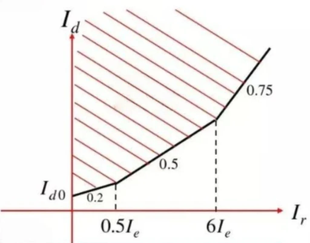
The differential pickup threshold
The bias slope characteristic (Slope 1 and Slope 2)
Harmonic restraint status (for inrush detection)
Zero-sequence compensation (if applicable)
When the differential current exceeds the operating threshold under the restraint conditions, the relay issues a trip command, activates alarms, and records fault data for post-event analysis.
Basic Differential Current Concept
At its core, transformer differential protection is based on comparing currents entering and leaving the protected zone:
Idiff=∣I1−I2∣
Under normal conditions, I₁ and I₂ are balanced, so Idiff is near zero. Under internal faults, this balance is disrupted and Idiff increases.
In a numerical relay, the currents are normalized and compensated before the differential characteristic is evaluated. This includes adjustments for CT ratio, transformer ratio, and vector group phase displacement to ensure accurate comparison.
Vector Group Compensation in Numerical Transformer Differential Protection
A numerical 87T relay can compensate for the phase displacement associated with the transformer’s vector group through software configuration. This eliminates the need for external CT connection adjustments and simplifies protection engineering.
Why Vector Group Compensation Is Required
Transformers with different vector groups introduce a phase shift between HV and LV currents. The relay must align both currents to a common phase reference before calculating differential current. Without correct compensation, the relay will see a persistent differential current under normal load conditions.
Common Vector Groups and Protection Considerations
The following table illustrates common vector groups and their compensation requirements. The actual phase relationship varies by vector group and must be correctly configured in the relay.
| Transformer Vector Group | Protection Consideration |
|---|---|
| Yy0 | No phase displacement |
| Dyn11 | Vector group compensation required |
| Yd1 | Vector group compensation required |
| Yd11 | Vector group compensation required |
Important Consideration
The actual phase relationship and relay compensation must be configured according to the transformer nameplate vector group and relay manufacturer’s documentation. Do not assume a fixed compensation method for all transformers with similar winding connections. Always verify the vector group from the nameplate and apply the compensation settings specified by the relay manufacturer.
CT Ratio and CT Saturation Compensation
CT Ratio Compensation
CT ratio compensation scales the measured secondary currents from both sides of the transformer to a common reference. Because CT ratios on the HV and LV sides are selected based on different primary current levels, the relay must compensate for these differences to ensure that, under normal load conditions, the currents are balanced before differential calculation. The compensation values are configured in the relay based on the actual CT nameplate ratings and transformer ratio.
CT Polarity Verification
CT polarity determines whether the secondary current is in phase with the primary current. Correct polarity is essential for differential protection. If a CT is connected with reversed polarity, the secondary current will be 180° out of phase, causing a persistent differential current under normal load. Polarity should be verified during commissioning using primary injection tests.
CT Saturation
CT saturation occurs when the CT core becomes magnetically saturated under high fault currents. This distorts the secondary current waveform and introduces measurement errors. During external faults, saturated CTs can produce apparent differential currents that may affect protection security. Proper CT sizing and selection of appropriate accuracy class and knee-point voltage help limit saturation effects.
Digital Restraint Against External Faults
Numerical relays use percentage restraint and, depending on the relay design, additional CT saturation detection or stabilization algorithms to improve security during external faults. The bias slope characteristic increases the operating threshold as through-current rises, helping the relay remain stable even when CT saturation occurs. The availability and implementation of additional CT saturation detection features vary by relay manufacturer and model.
Percentage-Biased Differential Protection in Numerical 87T Relays
Percentage bias is a protection characteristic where the relay’s operating threshold increases with through-current, ensuring stability during external faults while maintaining sensitivity for internal faults.
It is needed because CT errors and saturation generate residual differential currents that rise with fault current, which could otherwise cause misoperation. The relay compares differential current against a threshold derived from restraint current.
Dual-slope characteristics are often used, with a lower slope for the low-current region to maintain sensitivity and a higher slope for the high-current region to provide additional stability during severe external faults.
Harmonic Restraint in Numerical Transformer Differential Protection
Numerical relays use digital signal processing to analyze the harmonic content of differential currents. This enables them to distinguish between internal faults and non-fault conditions such as transformer energization or overexcitation, applying restraint when harmonic signatures are detected. The transformer differential relay harmonic restraint technology is the key to avoiding false tripping of transformer protection.
Transformer Magnetizing Inrush
When a transformer is energized, the core may saturate, producing a magnetizing inrush current that flows only on the energized side. This current creates an apparent differential current that could cause false tripping. Numerical relays detect the distinctive harmonic content of inrush and apply restraint to block tripping during this condition.
Second-Harmonic Restraint
Second-harmonic restraint is the primary method used to prevent false tripping during inrush. During inrush, the current waveform is highly distorted, with a prominent second harmonic component. Numerical relays calculate the ratio of the second harmonic to the fundamental frequency component using digital Fourier analysis. When this ratio exceeds the configured threshold, the relay applies restraint for the affected phase.
Overexcitation and Fifth-Harmonic Detection
Overexcitation of a transformer can occur during system overvoltage conditions or low-frequency operation. This produces a current waveform with elevated fifth harmonic content. Some numerical relays include fifth-harmonic detection to apply additional restraint during overexcitation, depending on the relay model and application. Digital harmonic analysis allows the relay to detect this condition and respond accordingly.
Digital Harmonic Analysis
Numerical relays perform harmonic analysis using digital signal processing techniques such as the Fast Fourier Transform (FFT) or discrete Fourier transform. These algorithms extract the harmonic components from the sampled current waveforms in real time. The relay can then evaluate harmonic ratios and apply restraint or blocking logic when specific harmonic patterns are detected. This digital approach provides greater accuracy, flexibility, and consistency compared to analog harmonic filtering methods.
Testing Numerical 87T Protection
Commissioning of a numerical 87T protection relay typically involves a structured test program to verify that all functions operate correctly according to the approved settings.
The following aspects are normally verified:
| Test Item | Description |
|---|---|
| CT polarity and CT ratio | Confirmed through primary injection tests to ensure correct phase relationship and scaling |
| Vector group configuration | Verified to confirm that phase compensation is correctly applied |
| Differential characteristic | Secondary injection tests to verify pickup threshold and bias slope(s) |
| Harmonic restraint | Inrush blocking function verified using harmonic injection |
| Trip logic | Confirmation that trip contacts, alarms, and output relays operate as configured |
| Binary inputs and outputs | Checked for correct signal mapping and response |
Testing usually includes both secondary injection (for relay internal functions) and primary injection (for complete CT-to-relay validation), following site commissioning procedures and the relay manufacturer’s test recommendations.
Core Functions of a Numerical Transformer Differential Relay
| Function | Purpose |
|---|---|
| 87T Differential | Internal transformer fault protection |
| Percentage Bias | Stability during external faults |
| Harmonic Restraint | Inrush discrimination |
| REF | Sensitive earth fault protection |
| Overcurrent | Backup protection |
| Overexcitation | V/Hz protection |
| Breaker Failure | Backup trip logic |
| Oscillography | Fault analysis |
| Event Recording | Sequence analysis |
| Self-Monitoring | Relay health monitoring |
Communication and Substation Integration
Modern numerical 87T relays are designed for seamless integration into digital substations and SCADA systems. They support a range of communication protocols and data interfaces that enable remote monitoring, control, and fault analysis. As a mature digital transformer differential relay, it has excellent compatibility with digital substation systems.
IEC 61850
IEC 61850 is the international standard for communication in substation automation. It provides a unified data model and communication framework for intelligent electronic devices (IEDs). Numerical 87T relays with IEC 61850 support can exchange protection and monitoring data across the substation network using standardised data objects and services.
GOOSE
GOOSE (Generic Object Oriented Substation Event) is a fast peer-to-peer communication service defined within IEC 61850. It allows the 87T relay to transmit trip commands, status signals, and interlocking information to other IEDs without the need for hardwired connections. This reduces wiring, improves response speed, and simplifies substation logic.
MMS
MMS (Manufacturing Message Specification) is used within IEC 61850 for client-server communication between IEDs and control systems. It supports functions such as setting read/write, event retrieval, and remote control. Substation operators and SCADA systems use MMS to access relay parameters and monitor protection status.
Modbus / IEC 60870-5-103
Modbus is widely used for simple, reliable communication between relays and SCADA systems. It is often used for data exchange with legacy equipment. IEC 60870-5-103 is another serial communication standard commonly used for protection device integration. Support for these protocols allows 87T relays to be deployed in both modern and existing substation environments.
Event and Fault Records
Numerical relays store detailed event logs and fault records. These records include time-stamped sequence of events (SOE), waveform capture (COMTRADE format), and pre/post-fault current data. This information is essential for post-event analysis, fault diagnosis, and protection performance verification. Remote access to these records is typically available via communication interfaces.
SCADA Integration
SCADA systems require reliable and secure communication with protection relays. The 87T relay supports integration through standard protocols, providing real-time data such as currents, status indications, alarms, and fault reports. This integration enables remote supervision, control, and coordination of transformer protection functions from a central control room.
Numerical vs Electromechanical Transformer Differential Protection
| Feature | Electromechanical | Numerical |
|---|---|---|
| Differential calculation | Hardware-based | Digital algorithm |
| Ratio compensation | Hardware / CT arrangement | Software configurable |
| Vector compensation | CT wiring | Software configurable |
| Bias characteristic | Hardware | Programmable |
| Harmonic restraint | Hardware | Digital processing |
| Event recording | Limited | Built-in |
| Communication | Limited | Multiple protocols |
| Additional functions | Separate devices | Often integrated |
Evolution of Transformer Differential Relays
The technology used for transformer differential protection has evolved through several generations. The following table provides a brief comparison of the key stages.
| Aspect | Electromechanical | Static | Numerical |
|---|---|---|---|
| Core Technology | Moving coils / induction disc | Solid-state analog circuits | Microprocessor-based digital processing |
| Compensation Method | Fixed CT connections / auxiliary CTs | CT connections / analog circuits | Software-configurable |
| Setting Adjustment | Physical adjustment / taps | Potentiometers / analog settings | Digital interface / software |
| Recording | Limited (target indicators) | Minimal | Comprehensive event / fault recording |
| Communication | None | Limited | Advanced protocol support |
| Flexibility | Low | Moderate | High |
This progression has enabled significant improvements in protection accuracy, setting flexibility, disturbance recording capability and communication integration. Numerical relays are now the predominant technology for transformer differential protection applications.
Applications of Numerical Transformer Differential Protection
| Application | Key Requirement | Benefit |
|---|---|---|
| Utility Substations | High-speed main protection for grid transformers | SCADA integration, selective tripping, event recording |
| Industrial Power Systems | Protect critical transformers in manufacturing/process plants | Fast fault isolation, minimize downtime |
| Renewable Energy Plants | Protect step-up transformers in wind and solar farms | Harmonic restraint suits frequent energization; plant SCADA support |
| Generator Step-Up Transformers | Fast differential protection for generator-connected transformers | Prevent damage, support generator protection coordination |
| Transformer Retrofit Projects | Upgrade aging conventional schemes | Reduce wiring and panel space, add fault recording and communication |
How to Select a Numerical Transformer Differential Relay
Selecting a numerical transformer differential relay requires careful evaluation of the transformer characteristics, protection requirements, and project-specific needs. The following factors should be considered:
| Selection Factor | Description |
|---|---|
| Transformer rating | MVA rating determines the required protection range and CT sizing |
| HV and LV voltages | Defines the voltage levels and insulation requirements for the relay application |
| CT ratio and secondary current | CT primary rating must match transformer currents; secondary rating (1A or 5A) must be compatible with relay inputs |
| Vector group | Must be supported by the relay’s vector group compensation settings |
| 87T characteristic | Single or dual-slope bias characteristic to match application needs |
| Harmonic restraint | Second harmonic (and optionally fifth harmonic) restraint for inrush and overexcitation security |
| REF / backup functions | Restricted earth fault or backup overcurrent functions may be integrated for additional protection |
| Communication protocols | IEC 61850, Modbus, IEC 60870-5-103, or other protocols required by substation automation or SCADA systems |
| Event recording | Fault recording and waveform capture for post-event analysis |
| Project standards | Compliance with applicable utility, industry, or EPC project specifications |
For a specific 87T relay product, see our Transformer Differential Protection Relay.
Numerical Transformer Differential Protection – Q&A
Q1. What is a numerical transformer differential relay?
A numerical transformer differential relay is a microprocessor-based protection device that uses digital signal processing to compare currents entering and leaving a transformer. It detects internal faults and provides high-speed tripping while maintaining stability during external faults, inrush, and other disturbances.
Q2. What is the difference between a numerical 87T relay and an electromechanical differential relay?
A numerical 87T relay uses digital processing, software-configurable settings, and advanced communication capabilities. An electromechanical relay uses physical coils and moving parts with fixed characteristics. Numerical relays offer higher accuracy, flexibility, and diagnostic functions such as fault recording.
Q3. How does a numerical 87T relay compensate for transformer vector groups?
The relay is configured with the transformer’s vector group (e.g., Yd11, Dyn11). Using software algorithms, it applies phase rotation and magnitude correction to align currents from both sides before differential calculation.
Q4. Can a numerical transformer differential relay compensate for CT ratio differences?
Yes. CT ratio compensation is performed internally by scaling the measured secondary currents to a common reference based on the CT ratios entered during configuration.
Q5. Why does a numerical 87T relay use percentage bias?
Percentage bias raises the operating threshold as through-current increases, ensuring stability during external faults when CT errors or saturation may produce residual differential current.
Q6. How does harmonic restraint prevent transformer inrush tripping?
During inrush, the current contains a high second harmonic component. The relay detects this harmonic content and applies restraint or blocks tripping, preventing false operation during transformer energization.
Q7. What is dual-slope differential protection?
Dual-slope protection uses two bias slopes: a lower slope for the low-current region to maintain sensitivity, and a higher slope for the high-current region to provide additional stability during severe external faults.
Q8. What communication protocols can numerical transformer differential relays support?
Common protocols include IEC 61850 (with GOOSE and MMS), Modbus RTU/TCP, and IEC 60870-5-103. Protocol support depends on the relay model.
Q9. What additional protection functions can be integrated into a numerical 87T relay?
Depending on the relay model, additional functions may include restricted earth fault (REF) protection, overcurrent protection, thermal overload protection, and breaker failure protection.
Q10. How is a numerical 87T relay tested?
Testing includes secondary injection to verify pickup, slope, harmonic restraint, and trip logic, as well as primary injection to validate the complete CT-to-relay path. CT polarity and vector group settings are also verified.
Q11. What CT information is required when configuring a numerical 87T relay?
Required CT information includes CT ratio (primary/secondary), secondary rated current (1A or 5A), connection type (star or delta), and polarity orientation.
Q12. What should be checked when selecting a numerical transformer differential relay?
Key selection criteria include transformer MVA rating, voltage levels, CT parameters, vector group, required protection functions, communication protocols, event recording capability, and compliance with project standards.



About Author

Hello, I'm Leno Zhang. I have 15 years of experience in the power relay protection industry with extensive pre-sales and after-sales project experience. Our company specializes in various complete sets of relay protection and automation equipment. I can assist customers in solving all practical on-site project challenges and provide optimal integrated solutions.
Tell Us Your Requirement
High Quality
Stable performance, reliable design, ensuring safe operation for power system protection and grid stability.
Fast Delivery
Timely delivery to support your urgent orders and project schedules efficiently and professionally at any time.
Best Warranty
Professional Warranty: Reliable after-sales support for stable relay protection and long-term customer satisfaction.