

-
Leon Zhang sales consultant
-
Email: zxl635973785@gmail.com
-
Phone/WhatsApp: +86 13655813266
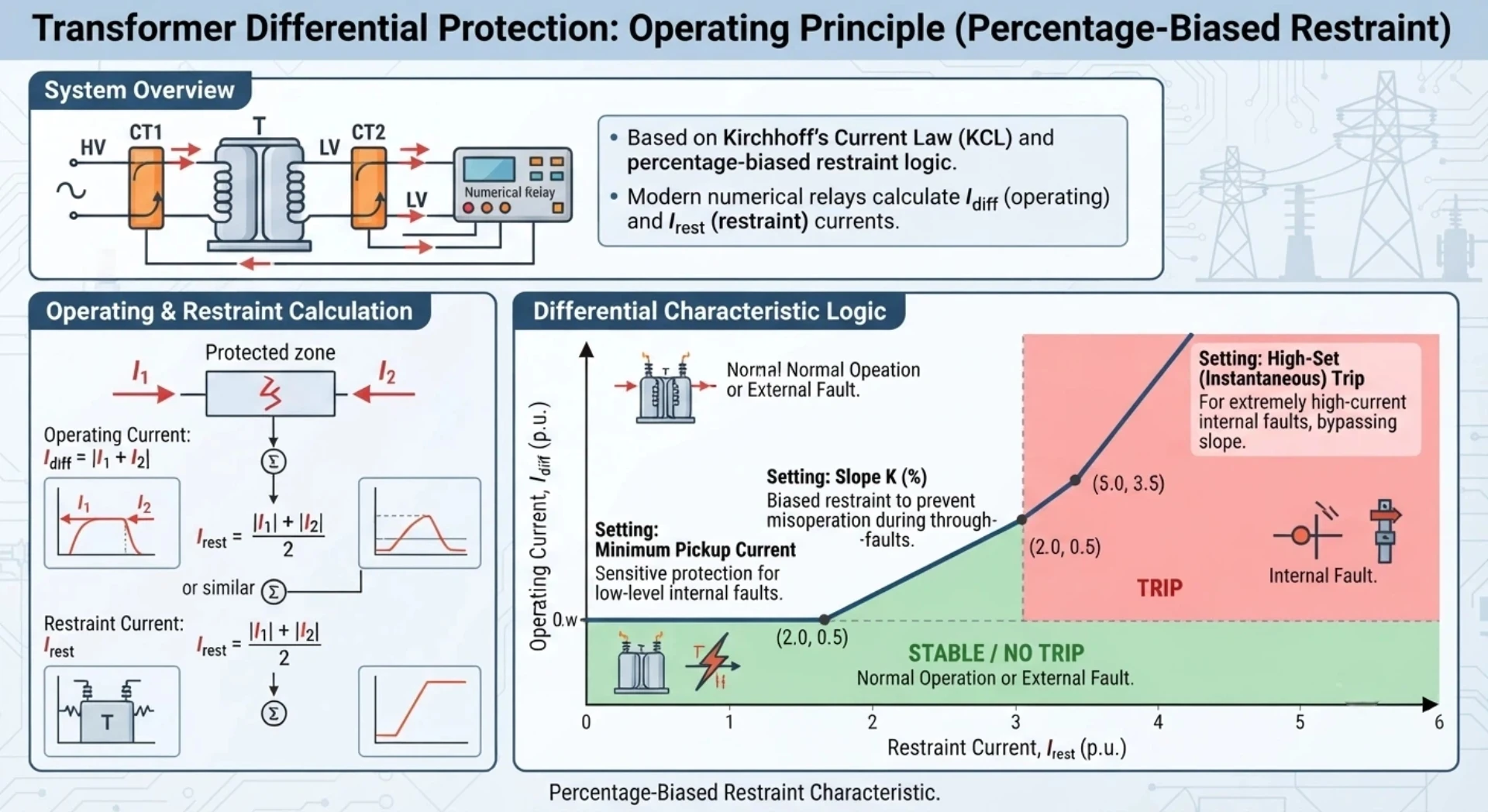
Transformer Differential Protection Working Principle: How 87T Protection Works
Introduction
Differential protection of a transformer is a high-speed protection method used to detect faults within the defined protection zone of a power transformer. An ANSI 87T relay compares the currents entering and leaving the transformer after accounting for transformer ratio, phase displacement and current transformer characteristics.
Under normal load and external fault conditions, the compensated currents should remain sufficiently balanced and the relay remains restrained. When an internal transformer fault produces a significant differential current, the 87T relay operates and issues a trip command.
This guide explains the Transformer Differential Protection Working Principle, including differential current, restraint current, percentage bias, CT compensation and harmonic restraint.
What Is Differential Protection of a Transformer?
Transformer differential protection, designated under the ANSI/IEC code 87T, is a fast and selective protection scheme designed to detect electrical faults occurring within the transformer’s protected zone. The principle is based on a current balance comparison: under normal conditions and external faults, the current entering the transformer approximately equals the current leaving it. The relay continuously monitors this balance. When an internal fault occurs, the balance is disrupted, creating a differential current that initiates a trip signal to isolate the transformer.
Protection Zone and Operating Principle
The protection zone is defined by the location of the current transformers on both sides of the transformer. Any fault occurring between these CTs is considered an internal fault. This method provides high-speed protection with a clearly defined boundary, making it inherently selective and capable of isolating faults without unnecessary delays.
Internal Fault Detection
Transformer differential protection is designed to detect faults within its protection zone, subject to the protection scheme, CT performance, and relay configuration. The types of internal faults that the system is designed to respond to include:
- Phase-to-phase short circuits
- Phase-to-ground faults
- Winding faults (including turn-to-turn faults)
- Internal lead and terminal faults
Under external fault conditions, currents remain balanced through the zone, so the relay remains stable. This inherent stability ensures that the protection operates only for faults inside the transformer, providing fast and selective clearing while maintaining system security.
How Does Differential Protection of a Transformer Detect Internal Faults?
HV-side CT → Current compensation → LV-side CT → Compare currents → Differential current → Internal fault? → 87T trip
The 87T relay compares currents from CTs on the transformer HV and LV sides. After ratio and vector group compensation, it calculates the differential current. Under normal conditions and external faults, the currents balance and the differential current is near zero. When an internal fault occurs, this balance is disrupted, the differential current exceeds the setting, and the 87T relay trips. This defines the protection zone and operating principle.
Transformer Differential Protection Zone
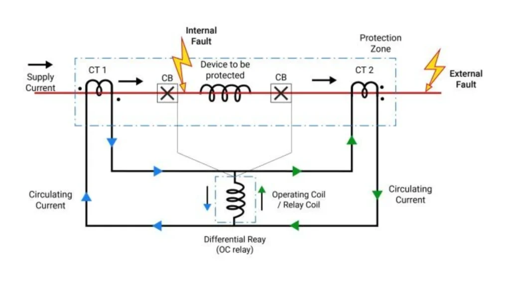
In differential protection of a transformer, the protection zone is normally defined between the CTs installed on the transformer sides. Faults inside this zone are treated as internal faults, while external faults should normally be restrained.
Zone Boundary and Operation
The differential protection zone is generally defined by the locations of the CTs. Faults inside the protected zone produce differential current, while faults outside the zone should normally be restrained.
- Internal Fault (Within Zone) – A fault occurring between CT1 and CT2 (inside the transformer) disrupts the current balance. The currents entering and leaving the zone become unequal, producing a differential current that causes the relay to trip.
- External Fault (Outside Zone) – A fault occurring outside the CT locations (e.g., on the connected busbar or outgoing feeders) does not disturb the current balance. The currents through CT1 and CT2 remain approximately equal, and the relay remains stable.
Key Principle
The CT locations define the protected zone. The relay compares currents at the zone boundaries; any imbalance indicates a fault inside the zone, while balance indicates normal or external fault conditions.
How Differential Protection of a Transformer Works
1. Current Measurement
The relay measures currents from the CTs installed on each side of the transformer. These currents represent the actual instantaneous values of current entering and leaving the protected zone. The measured values serve as the raw input for all subsequent protection calculations.
2. Current Compensation
Before any comparison can be made, the measured currents must be compensated to a common reference. This includes:
- Amplitude compensation – adjusting for differences in CT ratios and transformer voltage ratios
- Phase compensation – correcting for phase displacement introduced by the transformer vector group (e.g., YNd11, Dyn11)
Compensation ensures that, under normal load conditions, the currents from both sides are equal in magnitude and properly aligned in phase before comparison.
3. Differential Current Calculation
Once compensation is applied, the differential current is calculated as the vector difference between the compensated currents from both sides:
Idiff=∣I1−I2∣
Under normal conditions, I₁ and I₂ are approximately equal, so I_diff is small. Under internal fault conditions, I_diff becomes large, indicating a fault within the protected zone.
4. Restraint Current Calculation
In differential protection of a transformer, the relay evaluates the compensated current difference and restraint current to distinguish internal faults from external fault conditions.
Restraint current (or bias current) represents the through-current flowing across the transformer. It is calculated from the compensated currents and used to stabilise the relay during external faults.
A common definition is:
Irest=2∣I1∣+∣I2∣
Different relay manufacturers may use different restraint current definitions. The restraint current allows the relay to increase its operating threshold as the through-current increases.
5. Biased Differential Characteristic
The biased differential characteristic defines the relationship between differential current and restraint current. It consists of:
- A minimum pickup threshold – the lowest differential current required for operation
- Slope 1 – a moderate slope covering the lower restraint current region
- Slope 2 – a steeper slope covering the high restraint current region
The relay operates only when the differential current exceeds the characteristic curve defined by the restraint current and slope settings.
6. Trip Decision
The trip decision is made when the differential current exceeds the operating threshold defined by the characteristic curve, subject to additional security checks such as:
- Harmonic restraint – preventing operation during transformer inrush
- CT saturation detection – providing additional stability during severe external faults
When all operating conditions are met, the relay issues a trip command to isolate the transformer from the system.
Restraint Current
Restraint current provides stability during external faults and measurement errors. It is a stabilizing quantity that increases the relay’s operating threshold as the through-current through the transformer rises.
Why Restraint Current Is Required
During an external fault, the fault current flows through the transformer but remains outside the protection zone. In theory, the differential current should be zero. However, in practice, factors such as CT errors and CT saturation during high-current faults produce a residual differential current. Restraint current ensures that the relay remains stable under these conditions.
How Restraint Current Works
The following sequence illustrates the role of restraint current during an external fault:
External Fault Occurs
- High through-current flows through the transformer and CTs
CT Error / Saturation
- CT performance deteriorates under high fault current
- A small residual differential current appears
High Restraint
- The relay calculates a high restraint current based on the through-current
- The operating threshold is raised proportionally
87T Remains Stable
- The small residual differential current remains below the raised threshold
- The relay does not trip
Core Principle
The relay does not trip based on differential current alone. Instead, it compares the differential current against a threshold that increases with the restraint current. This principle allows the relay to remain stable during high-current external faults while maintaining sensitivity for internal faults.
Percentage-Biased Differential Protection Logic
What Is Percentage Bias?
Percentage-biased protection is widely used in differential protection of power transformers because it improves relay stability during external faults while maintaining sensitivity to internal faults.
Percentage bias, also known as percentage restraint, is a protection characteristic where the operating threshold increases in proportion to the through-current flowing through the transformer. Instead of operating at a fixed differential current level, the relay requires the differential current to exceed a percentage of the restraint current before tripping is permitted.
In a percentage-biased relay, the operate characteristic is expressed as:
Idiff>K×Irest+Ipickup
Where K is the bias slope, I_rest is the restraint current, and I_pickup is the minimum operating threshold.
Why Is Bias Required?
Under ideal conditions, the differential current during normal load and external faults should be zero. In practice, however, several factors generate a residual differential current:
- CT ratio errors and mismatch between HV and LV CTs
- CT saturation under high fault currents
- Transformer tap changer variations (OLTC)
- Measurement inaccuracies in the relay
If the protection operated at a fixed threshold, these error currents could cause unwanted tripping during external faults, especially when fault currents are high. Percentage bias addresses this by raising the operating threshold as the through-current increases, ensuring that the relay remains stable under all external fault conditions while preserving sensitivity for internal faults.
How Does the Slope Characteristic Work?
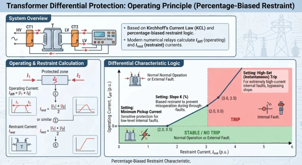
The bias slope defines the rate at which the operating threshold increases with restraint current. A typical characteristic consists of:
- Minimum Pickup – A fixed lower threshold below which the relay does not operate, regardless of restraint current
- Slope Region – The operating threshold rises linearly with restraint current according to the defined slope
- High-Current Region – The slope may increase at higher restraint current levels to accommodate CT saturation effects
The steeper the slope, the more restraint is applied, increasing stability during external faults but reducing sensitivity for internal faults. The characteristic is designed to ensure that the relay operates for internal faults across all fault current levels, while remaining stable for external faults within the CT performance limits.
Important Note:
Bias slope implementation, definitions of differential and restraint currents, and characteristic curve shapes vary between relay manufacturers. Always refer to the specific relay manual for the exact operating characteristic and setting definitions applicable to your relay.
Harmonic Restraint in Transformer Differential Protection
Transformer Energization
When a transformer is energized, the sudden application of voltage can drive the transformer core into saturation. This results in a magnetizing inrush current that flows only on the energized side of the transformer. Because this current is not balanced by current on the other side, the relay sees a large differential current.
Magnetizing Inrush
Inrush current can reach several times the transformer rated current and, if not properly handled, would cause the differential protection to operate incorrectly during normal energization. However, inrush current has distinct waveform characteristics that allow the relay to distinguish it from actual internal faults.
Harmonic Components
During inrush, the current waveform is highly distorted and contains significant harmonic content. The second harmonic component is particularly prominent, typically ranging from 15% to 40% of the fundamental frequency component. This harmonic signature is the key feature used by the relay to identify inrush conditions.
Relay Recognition
The relay continuously measures the harmonic content of the differential current. It calculates the ratio of the second harmonic to the fundamental component. When this ratio exceeds the set threshold, the relay recognises the condition as inrush rather than an internal fault.
Restraint / Blocking
Upon recognising inrush, the relay applies restraint by raising the operating threshold or blocking the trip output entirely for the affected phase. Some relays also apply cross-blocking, where detection of inrush on one phase restrains operation on all three phases. This ensures that the transformer can be safely energized without the differential protection tripping, while full protection remains available immediately after inrush subsides.
Why Does It Restrain?
Harmonic restraint is applied because the harmonic content during inrush provides a reliable indicator that the differential current is not caused by an internal fault. Internal faults typically produce currents with low harmonic content, allowing the relay to respond quickly when a true fault occurs. The restraint is therefore a security measure that prevents false tripping during a normal operational condition, without compromising protection dependability for actual faults.
Role of CTs in Transformer Differential Protection
CTs provide the current measurements essential for differential protection. Three key aspects must be considered.
| Aspect | Description |
|---|---|
| CT Ratio Matching | Ensures secondary currents match primary currents on each side. The relay compensates for ratio differences. Incorrect entries cause persistent differential current. |
| CT Polarity | Determines phase relationship between primary and secondary currents. Reversed polarity produces differential current even under normal load. Verified through primary injection testing. |
| CT Saturation | Occurs under high fault currents, causing distorted secondary waveforms. May produce spurious differential currents during external faults. Bias slope helps mitigate this effect by raising the operating threshold. |
For detailed CT selection and testing, see our transformer differential protection testing and CT testing resources.
What Causes Unwanted Differential Current?
Under ideal conditions, the differential current during normal operation and external faults should be near zero. In practice, however, various factors can produce an unwanted differential current that may affect relay performance if not properly addressed.
CT Ratio Mismatch
CTs on the HV and LV sides are selected based on different primary current ratings. If the CT ratios do not correctly match the transformer voltage ratio, or if the relay settings do not compensate for the difference, a persistent differential current will appear under normal load.
CT Polarity Error
If one CT is connected with reversed polarity, the secondary currents from both sides will be 180° out of phase. This creates a differential current even during normal load conditions and may cause the relay to trip incorrectly.
CT Saturation
During high-current through-faults, CT cores may become saturated, causing distorted secondary current waveforms. This distortion introduces errors in the current measurement and can produce a spurious differential current even though the fault is outside the protection zone.
Transformer Ratio / Vector Compensation Error
The relay must compensate for the transformer voltage ratio and vector group phase displacement. If the vector group setting is incorrect or phase compensation is not properly applied, the compensated currents will not be aligned, resulting in a differential current under normal operating conditions.
OLTC Tap Position
Transformers equipped with on-load tap changers (OLTC) operate at turns ratios that vary from the nominal value. If the relay compensation is based on the nominal ratio only, tap changes will introduce a differential current that increases with the tap deviation.
Wiring Errors
Errors in CT wiring, such as incorrect connections, open circuits, or short circuits, can cause current signals to be missing, misrouted, or distorted. These wiring issues often result in significant differential current and may cause protection misoperation.
Standards Related to Transformer Differential Protection
- IEC 60255: Numerical protection relay testing and performance requirements
- IEC 60076: Power transformer design, protection and operation specifications
- IEC 61869: Current transformer technical requirements and testing methods
- IEEE C37.110:Transformer differential protection industry practice standard
All commissioning processes cover FAT (Factory Acceptance Test) and SAT (Site Acceptance Test) full-link verification, meeting international project delivery requirements.
Field Commissioning Best Practices
- Verify transformer vector group before confirming all relay settings
- Never rely solely on design drawings; conduct on-site CT polarity and ratio recheck
- Complete CT testing first, then relay parameter calibration
- Test each differential protection zone independently to avoid missing defects
- Reserve relay disturbance files and test reports for project archives
- Simulate actual fault and inrush current conditions for full-coverage testing
- Form standardized SAT documents to ensure traceability
Transformer Differential Protection – Q&A
Q1. What is differential protection of a transformer?
Differential protection of a transformer is a high-speed protection method that compares the compensated currents on the transformer sides to detect internal faults within the protected zone. It is commonly implemented using an ANSI 87T differential protection relay.
Q2. How does transformer differential protection work?
The protection measures currents on both sides of the transformer, compensates for CT ratio differences and phase displacement, and calculates the differential current. Under normal and external fault conditions, the differential current is near zero. When an internal fault occurs, the differential current increases and causes the relay to trip.
Q3. What is the ANSI code for transformer differential protection?
The ANSI code for transformer differential protection is 87T.
Q4. What is differential current in transformer protection?
Differential current is the vector difference between the compensated currents from the HV and LV sides of the transformer. Under normal conditions, differential current is near zero. Under internal faults, it becomes significant and initiates the tripping logic.
Q5. What is restraint current?
Restraint current (or bias current) is a stabilizing quantity used to prevent unwanted tripping during external faults. It is derived from the through-current and increases the relay’s operating threshold as fault current rises.
Q6. Why does transformer differential protection use percentage bias?
Percentage bias is used to maintain stability during external faults. While differential current should ideally be zero, practical factors such as CT errors and saturation generate residual differential currents. Percentage bias raises the operating threshold as through-current increases, ensuring the relay remains stable while maintaining sensitivity for internal faults.
Q7. Why is CT polarity important in differential protection?
CT polarity determines the phase relationship between primary and secondary currents. Correct polarity ensures that currents entering and leaving the transformer are properly aligned for differential calculation. Reversed polarity causes a persistent differential current even under normal load, leading to possible misoperation.
Q8. How does transformer vector group affect differential protection?
The vector group defines the phase displacement between HV and LV windings. The relay must be configured with the correct vector group to properly align currents before differential calculation. Incorrect vector group settings result in phase mismatch and persistent differential current.
Q9. Why does differential protection not trip during external faults?
During external faults, the fault current flows through the transformer but remains outside the protection zone. The currents entering and leaving the zone remain balanced, so the differential current remains near zero. The relay remains stable and does not trip, even under high fault current conditions.
Q10. Why can transformer energization cause differential current?
Transformer energization produces magnetizing inrush current that flows only on the energized side, creating an apparent differential current. Without special measures, this would cause the relay to trip. Harmonic restraint is used to distinguish inrush from internal faults and prevent false tripping.
Q11. What is harmonic restraint in transformer differential protection?
Harmonic restraint is a feature that prevents the relay from tripping during transformer energization. During inrush, the current contains significant second harmonic content. The relay detects this harmonic signature and applies restraint or blocks the trip output until the inrush subsides.
Q12. What is the difference between differential protection and overcurrent protection?
Differential protection compares currents on both sides of the transformer and provides fast, selective clearing of internal faults with a defined protection zone. Overcurrent protection responds to excessive current magnitude and is typically used as backup protection, responding to faults anywhere in the system but with less selectivity and longer time delays.
Q13.What is the working principle of differential protection of a transformer?
The working principle is based on current comparison. Under normal operating conditions and external faults, the compensated currents entering and leaving the transformer are approximately balanced. For an internal fault, the current balance is disturbed and a differential current develops, causing the 87T protection element to operate when the configured conditions are met.



About Author

Hello, I'm Leno Zhang. I have 15 years of experience in the power relay protection industry with extensive pre-sales and after-sales project experience. Our company specializes in various complete sets of relay protection and automation equipment. I can assist customers in solving all practical on-site project challenges and provide optimal integrated solutions.
Tell Us Your Requirement
High Quality
Stable performance, reliable design, ensuring safe operation for power system protection and grid stability.
Fast Delivery
Timely delivery to support your urgent orders and project schedules efficiently and professionally at any time.
Best Warranty
Professional Warranty: Reliable after-sales support for stable relay protection and long-term customer satisfaction.