

-
Leon Zhang sales consultant
-
Email: zxl635973785@gmail.com
-
Phone/WhatsApp: +86 13655813266
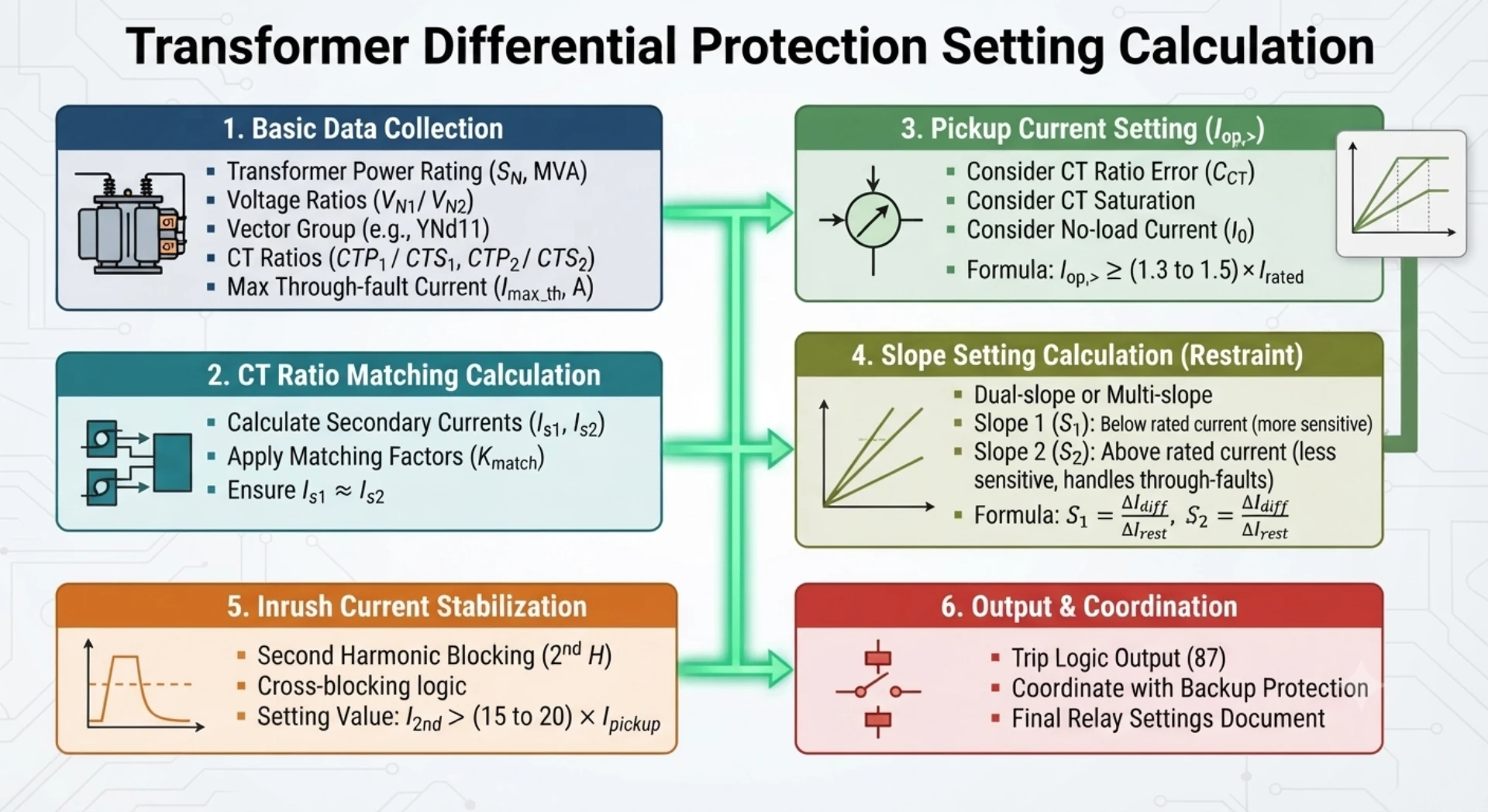
Transformer Differential Protection Setting: Parameters, Calculation and Guidelines
Introduction
Transformer differential protection setting defines the operating parameters used to distinguish internal transformer faults from normal load, external faults, and transformer energization conditions. The main parameters include differential pickup, percentage bias or restraint slope, harmonic restraint, CT ratio, transformer vector group compensation, and related trip or alarm settings.
These settings must be coordinated with the transformer rating, CT characteristics, system fault conditions, relay model, and protection philosophy. The ANSI 87T differential protection function is one of the main applications of this setting process.
This guide explains the main transformer differential protection settings, what each parameter does, and how engineers can verify the settings before commissioning. For detailed mathematical calculations, see our Differential Protection Relay Setting Calculation guide.
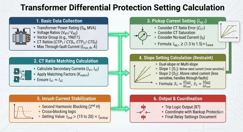
What Is Transformer Differential Protection Setting?
Transformer differential protection setting is the process of defining the relay’s operating parameters to ensure it correctly distinguishes between internal transformer faults and all other system conditions. The primary purpose of setting is to establish a secure operating region where the relay remains stable during normal load, magnetizing inrush, and external faults, while maintaining sufficient sensitivity to detect internal faults such as winding short circuits and core failures. Proper setting calculation involves determining pickup thresholds, bias slopes, and harmonic restraint values based on transformer nameplate data, CT parameters, and system fault levels.
For a detailed explanation of the operating principle, see Transformer Differential Protection Working Principle.
Differential Pickup Setting
Differential Pickup Current Setting
The differential pickup current (Idiff> or minimum operating current) is the threshold above which the differential protection element initiates its tripping logic, subject to the relay’s characteristic.
Effects of Improper Setting
Too Low
If the pickup is set too low, the relay may maloperate due to spurious differential currents caused by:
- CT mismatch and ratio errors
- Measurement errors
- OLTC tap variations
- Residual current during external faults
Too High
If the pickup is set too high, the relay may fail to detect:
- Small internal faults
- Turn-to-turn winding faults with low fault current
- Incipient faults
Engineering Principle
The pickup setting must be selected within a defined design window:
- Lower limit: Above the maximum expected unbalanced current under normal and external fault conditions (ensures stability)
- Upper limit: Below the minimum differential current expected for any internal fault requiring clearance (ensures sensitivity)
The final pickup value should provide sufficient sensitivity for the minimum internal fault while remaining above the expected maximum unbalanced current.
Typical Range
For practical applications, the differential pickup is typically set between 15% and 40% of transformer rated current, depending on:
- CT accuracy class
- Transformer tap range
- Application requirements
- Relay type
Bias / Slope Setting
What Is Bias Slope?
Bias slope (also known as percentage restraint slope) defines how the relay’s operating threshold increases as the through-current flowing through the transformer rises. It establishes the relationship between differential current and restraint current, forming the characteristic curve that determines the relay’s operating boundary.
Why Is Bias Slope Required?
Under ideal conditions, differential current should remain near zero during external faults. However, practical factors such as CT ratio errors, CT saturation, and measurement inaccuracies generate spurious differential currents that increase with fault current magnitude. The bias slope allows the relay to tolerate these errors by raising the operating threshold proportionally with the through-current, ensuring stability during high-current external faults while maintaining sensitivity for internal faults.
Slope 1 – Low-Current Region
Slope 1 applies to the low restraint current region, typically corresponding to normal load and light through-fault conditions. In this region, steady-state errors such as CT ratio mismatch and tap changer variations are the dominant sources of unbalance. A lower slope setting provides high sensitivity for detecting minor internal faults, as the differential current required for operation increases only gradually with restraint current.
Slope 2 – High Through-Fault Region
Slope 2 applies to the high restraint current region, typically associated with severe external faults and heavy through-fault conditions. In this region, CT saturation becomes the dominant error source, introducing substantial differential current during the first few cycles of fault. A higher slope setting increases the operating threshold significantly, ensuring relay stability during severe external faults when CT performance is compromised.
Setting Considerations
The bias slope setting must balance sensitivity and stability across the full range of operating conditions:
- Slope 1 is typically set between 20% and 35%, providing sufficient coverage for steady-state errors while maintaining high sensitivity.
- Slope 2 is typically set between 50% and 80%, accommodating CT saturation effects during high-current external faults.
The final slope settings depend on CT performance characteristics, transformer impedance, fault levels, and the specific relay type. Always refer to the manufacturer’s manual for the exact characteristic curve and setting procedure.
Typical Setting Considerations
When configuring a transformer differential protection relay, several key parameters must be carefully selected based on the specific application. The following table outlines the primary settings and their engineering considerations.
| Parameter | Engineering Consideration |
|---|---|
| Differential Pickup | Must balance sensitivity and stability |
| Slope 1 | Determines restraint in lower through-current region |
| Slope 2 | Provides greater stability under high through-fault current |
| 2nd Harmonic Restraint | Used to prevent unwanted operation during magnetizing inrush |
| 5th Harmonic Restraint | May be used for overexcitation detection/restraining depending on relay |
| Time Delay | Usually coordinated with the protection philosophy |
Important Note:
Typical values vary by relay model and project requirements. Always use the setting definitions and permissible ranges specified in the selected relay manufacturer’s manual. The table above is for reference only and should not be used as a substitute for formal setting calculations and manufacturer-specific guidance.
Transformer Differential Protection Harmonic Restraint Setting
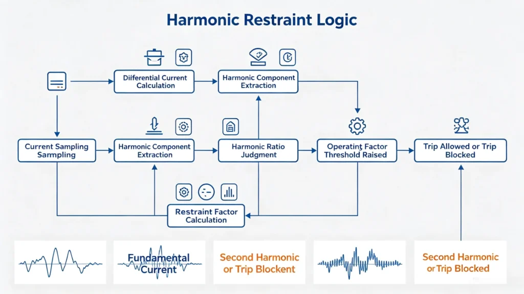
Harmonic restraint is a stabilizing feature used in transformer differential protection to prevent unwanted tripping during conditions that produce high levels of harmonic distortion in the current waveform. The relay detects specific harmonic components and increases the operating threshold or blocks the trip output when these components exceed a preset percentage of the fundamental current.
2nd Harmonic Restraint
The second harmonic component is the primary harmonic used for restraining differential protection during transformer magnetizing inrush. When a transformer is energized, the inrush current contains a significant second harmonic content, typically ranging from 15% to 40% of the fundamental frequency component. The relay measures this ratio and applies restraint when the second harmonic exceeds the set threshold, preventing false tripping.
Typical Setting Range: 10% to 25% (relay-specific)
5th Harmonic Restraint
Some relays provide a fifth harmonic restraint feature, which may be used in applications where overexcitation conditions are a concern. Overexcitation produces a current waveform with elevated fifth harmonic content, and the relay can apply restraint to avoid maloperation during such events. However, the availability and implementation of fifth harmonic restraint depend on the specific relay model and manufacturer’s algorithm. Not all transformer differential relays employ this feature, and the method of application varies significantly between different protection platforms.
Important Note:
Harmonic restraint settings, including the selection of harmonic order and the method of application, vary between relay manufacturers. Always refer to the specific relay manual for available harmonic restraint functions, setting definitions, and permissible ranges. The typical values and descriptions provided above are for general reference only.
CT Ratio Setting
CT Ratio Setting for Transformer Differential Protection
The CT ratio setting defines the relationship between the primary current flowing through the transformer and the secondary current delivered to the relay. This setting must match the actual CT nameplate ratings installed on site for both the HV and LV sides of the transformer.
Key Elements:
- CT Primary Ratio – The primary current rating of the CT, selected based on the transformer rated current and expected fault levels
- CT Secondary Rating – Typically 1A or 5A, which must match the relay’s analog input design
- HV CT – The CT installed on the high-voltage side of the transformer
- LV CT – The CT installed on the low-voltage side of the transformer
Important Considerations:
- CT Mismatch – The CT ratios on the HV and LV sides are often different due to the transformer voltage ratio. The relay must compensate for this difference internally through its setting parameters.
- CT Saturation – Under high fault currents, CT saturation can occur, causing distorted secondary currents. Proper CT sizing and relay settings help mitigate the impact of saturation.
Critical Requirement:
CT ratio settings must match the actual CT nameplate ratings on site. Incorrect CT ratio entries will result in erroneous current measurements and may compromise protection performance.
For step-by-step calculations, see our CT secondary current calculation example.
Transformer Vector Group Setting
Transformer Vector Group and Phase Compensation Setting
The transformer vector group setting defines the phase displacement and magnitude relationship between currents on the HV and LV sides. Correct configuration of this setting is essential for the relay to correctly calculate differential current under normal load and through-fault conditions.
Phase Displacement
Transformers with different vector groups introduce a phase shift between primary and secondary currents. Common vector groups include:
- YNd11 – 30° phase displacement
- Dyn11 – 30° phase displacement
- Yy0 – 0° phase displacement
- Yd1 – 30° phase displacement
The relay must compensate for this phase shift to ensure that currents from both sides are properly aligned before differential current is calculated.
Amplitude Compensation
In addition to phase displacement, the relay must also compensate for differences in current magnitude between the HV and LV sides. This compensation is typically based on the transformer ratio and CT ratios, allowing the relay to compare currents on a common reference basis.
Compensation Method – Important Consideration
For a YNd11 transformer, the relay must correctly account for the transformer phase displacement and current magnitude relationship. Whether compensation is performed internally by the numerical relay or through external CT connections depends on the relay design.
Some relays perform full compensation through software settings, where the user simply enters the vector group and CT parameters. Other relays may require specific CT connection configurations to achieve proper compensation. The implementation varies significantly across manufacturers and relay models.
Critical Requirement
Always consult the specific relay manual to confirm:
- Whether vector group compensation is handled internally or externally
- The correct setting parameters for the transformer vector group
- Any special CT connection requirements for the relay
Incorrect vector group settings will result in phase mismatch, persistent differential current, and potential relay maloperation.
What Is Zero-Sequence Current?
Zero-sequence current flows when a ground fault occurs in a system that has a grounded neutral. The magnitude and path of this current depend on the transformer winding configuration and the system grounding arrangement.
Transformer Winding Connection Impact
- In a star-connected winding with a grounded neutral, zero-sequence current can flow through the neutral path and appears as phase current on that side.
- In a delta-connected winding, zero-sequence current is trapped within the delta and does not appear in the line currents.
When a transformer has one star-grounded winding and one delta winding, a ground fault on the star side produces zero-sequence current that appears on the star side phase currents but is not present in the delta side line currents. If the relay calculates differential current without compensation, this imbalance may be seen as a false differential current.
Relay Compensation
Numerical relays can apply zero-sequence compensation to remove the zero-sequence component from the measured currents before differential calculation. This ensures that only the positive- and negative-sequence components are compared, avoiding maloperation during ground faults.
Important Note:
Function availability depends on relay model and transformer connection. Not all relays provide zero-sequence compensation, and the method of implementation varies between manufacturers. Always confirm the available functions and correct compensation settings in the specific relay manual for your application.
Transformer Inrush Restraint Setting
Why Transformer Inrush Causes Differential Current
When a transformer is energized, the sudden application of voltage can produce a magnetizing inrush current that is rich in harmonics and may be several times the transformer rated current. Because inrush current flows only on the energized side of the transformer, the relay sees a large differential current that resembles an internal fault. Without special measures, the differential protection would trip incorrectly during transformer energization.
2nd Harmonic Restraint
The most common method used to prevent inrush tripping is second harmonic restraint. During inrush, the current waveform is highly distorted and contains a significant second harmonic component, typically ranging from 15% to 40% of the fundamental. The relay measures the ratio of the second harmonic to the fundamental frequency component. When this ratio exceeds the set threshold, the relay restrains operation for that phase.
Cross-Blocking / Phase Blocking
Some relays provide cross-blocking, where the detection of inrush on one phase can be used to restrain the differential protection on all three phases. This can be beneficial during inrush conditions where one phase exhibits a lower second harmonic content than the others. Function availability depends on the specific relay model.
How to Verify Inrush Restraint
Verification of inrush restraint settings typically involves:
- Simulating inrush conditions using a secondary injection test set with harmonic injection capability
- Checking that the relay correctly identifies inrush and applies restraint
- Confirming that the relay does not trip when inrush currents are simulated
For detailed test procedures, see our transformer differential protection testing guide.
Protection Setting Table
| Setting Parameter | Purpose | Typical Consideration |
|---|---|---|
| Differential Pickup | Minimum operating threshold | Sensitivity vs stability |
| Bias Slope 1 | Low-current restraint | CT mismatch / normal errors |
| Bias Slope 2 | High-current restraint | External fault stability |
| 2nd Harmonic | Inrush restraint | Transformer energization |
| 5th Harmonic | Overexcitation-related restraint/alarm | Relay dependent |
| CT Ratio | Current scaling | Match actual CT |
| Vector Group | Phase compensation | Match transformer nameplate |
| Zero-Sequence Compensation | Ground-fault compensation | Application dependent |
| Trip Delay | Operation timing | Protection coordination |
Transformer Differential Protection Setting Example
The following table provides an example of typical transformer differential protection settings. The actual values must be determined based on the transformer rating, CT parameters, fault conditions, relay characteristics, and project requirements.
| Parameter | Example Setting |
|---|---|
| Differential Pickup | Project-specific |
| Slope 1 | Project-specific |
| Slope 2 | Project-specific |
| 2nd Harmonic Restraint | Project-specific |
| CT Ratio | 400/1A / 1200/1A |
| Vector Group | YNd11 |
Important Note:
All settings shown above are project-specific and must be calculated based on transformer nameplate data, CT ratios, fault studies, and relay manufacturer requirements. The values provided are for illustrative purposes only and should not be used as final settings.
See the complete calculation process in our Differential Protection Relay Setting Calculation guide.
Common Transformer Differential Protection Setting Problems
The following table identifies common operational issues that may arise during transformer differential protection and their potential root causes related to incorrect settings.
| Problem | Possible Setting Cause |
|---|---|
| False trip during energization | Incorrect harmonic restraint |
| Differential current during load | Wrong CT ratio / vector group |
| External fault maloperation | Insufficient bias / slope |
| Internal fault not detected | Pickup too high |
| Ground fault sensitivity reduced | Incorrect zero-sequence compensation |
Important Note:
These issues may also result from non-setting-related factors such as CT wiring errors, hardware faults, or external system conditions. A systematic investigation should be conducted to identify the root cause before modifying any relay settings.
How to Verify Transformer Differential Protection Settings
| Verification Step | What to Check |
|---|---|
| Parameter Check | Confirm CT ratio, vector group, pickup, slope, and harmonic restraint values match calculation results |
| CT Ratio and Polarity Check | Confirm CT ratios match nameplate ratings; verify CT polarity connections are correct |
| Pickup Test | Verify relay operates at the set pickup threshold |
| Bias / Slope Test | Verify relay operates correctly on the bias characteristic |
| Harmonic Restraint Test | Verify relay remains stable during simulated inrush conditions |
| Trip Logic Verification | Verify trip command and alarms operate correctly |
Functions of Transformer Differential Protection Relay
The transformer differential protection relay is a numerical relay designed to provide high-speed main protection for power transformers. It operates on the bias differential principle, ensuring stability during external faults and through-fault conditions while maintaining sensitive detection of internal winding faults. The relay supports flexible CT ratio and phase compensation, with harmonic restraint to prevent false tripping during transformer energization.
Key 87T relay functions include transformer differential protection, percentage-biased differential protection, high-set differential protection, harmonic restraint, CT ratio compensation, vector group compensation, and fast trip output for internal transformer faults.
Advanced event and fault recording functions enable detailed post-event analysis, while multiple communication interfaces allow integration into modern substation automation systems.
| 87T Relay Features | Purpose |
|---|---|
| Differential Protection | Detect internal transformer faults |
| Percentage Bias / Restraint | Maintain stability during external faults |
| High-Set Differential | Provide fast operation for severe internal faults |
| 2nd Harmonic Restraint | Prevent false tripping during transformer inrush |
| 5th Harmonic Restraint | Provide restraint or alarm for overexcitation where supported |
| CT Ratio Compensation | Correct current magnitude differences |
| Vector Group Compensation | Correct phase displacement between transformer windings |
| Trip Logic | Rapidly isolate the transformer during internal faults |
FAQ
Q1. What is transformer differential protection setting?
Transformer differential protection setting is the process of defining the relay’s operating parameters to ensure correct operation for internal faults and stability for external faults, inrush, and overexcitation. The setting defines the actual values entered into the relay.
Q2. What Are the Main Transformer Differential Protection Settings?
The main transformer differential protection settings include differential pickup, bias slope, harmonic restraint, CT ratio, vector group compensation, zero-sequence compensation where applicable, and trip-related parameters. The exact settings depend on the transformer, CT characteristics, relay model, and project requirements.
Q3. How is differential pickup selected?
Differential pickup is selected to be above the maximum expected unbalanced current under normal and external fault conditions, while remaining below the minimum differential current expected for internal faults. This ensures both stability and sensitivity.
Q4. What is the purpose of bias slope in transformer differential protection?
Bias slope raises the operating threshold as through-current increases, allowing the relay to remain stable during external faults when CT errors and saturation may produce spurious differential currents. Slope 1 covers the low-current region, while Slope 2 addresses high through-fault conditions.
Q5. How should 2nd harmonic restraint be set?
The 2nd harmonic restraint is set to a percentage of the fundamental current, typically within the range specified by the relay manufacturer. The setting must be high enough to prevent blocking during internal faults with harmonic content, yet low enough to secure restraint during inrush.
Q6. How Does Transformer Vector Group Affect Differential Protection Settings?
The transformer vector group determines the phase displacement between winding currents. The differential protection relay must compensate for this phase displacement before calculating differential current. Incorrect vector group configuration can produce persistent differential current and cause protection maloperation.
Q7. How does CT ratio affect transformer differential protection settings?
CT ratio determines the secondary current magnitude seen by the relay. An incorrect CT ratio entry leads to incorrect compensated currents, affecting all derived values including differential and restraint currents.
Q8. What is the difference between differential protection setting and setting calculation?
Setting calculation is the analytical process of determining the appropriate values based on transformer data, CT parameters, and fault studies. The setting is the final step where those calculated values are entered into the relay. Calculation defines the values; setting applies them.
Q9. How should transformer differential protection settings be verified?
Verification includes parameter checks, CT ratio and polarity checks, secondary injection tests for pickup and slope, harmonic restraint tests, and trip logic verification.
Q10. Can Transformer Differential Protection Settings Be Customized for a Project?
Yes. Transformer differential protection settings should be determined according to the transformer nameplate data, CT characteristics, system fault levels, transformer vector group, relay characteristics, and project protection requirements. The final values should be verified through calculation and relay testing before commissioning.
Q11. What are the main 87T relay functions?
The main 87T relay functions include transformer differential protection, percentage-biased differential protection, high-set differential protection, harmonic restraint, CT ratio and vector group compensation, and fast tripping for internal transformer faults. These functions allow the relay to detect internal transformer faults while remaining stable during external faults and transformer energization.
Conclusion
Transformer differential protection settings must be coordinated with the transformer nameplate data, CT characteristics, vector group, relay model and system protection requirements. The key 87T parameters include differential pickup, bias slope, harmonic restraint, CT ratio and phase compensation.
The final settings should be verified through protection calculations, relay testing and commissioning procedures before the transformer is placed into service.
For a detailed calculation example, see our Differential Protection Relay Setting Calculation guide. For the relay itself, see our Transformer Differential Protection Relay product page.



About Author

Hello, I'm Leno Zhang. I have 15 years of experience in the power relay protection industry with extensive pre-sales and after-sales project experience. Our company specializes in various complete sets of relay protection and automation equipment. I can assist customers in solving all practical on-site project challenges and provide optimal integrated solutions.
Tell Us Your Requirement
High Quality
Stable performance, reliable design, ensuring safe operation for power system protection and grid stability.
Fast Delivery
Timely delivery to support your urgent orders and project schedules efficiently and professionally at any time.
Best Warranty
Professional Warranty: Reliable after-sales support for stable relay protection and long-term customer satisfaction.