

-
Leon Zhang sales consultant
-
Email: zxl635973785@gmail.com
-
Phone/WhatsApp: +86 13655813266
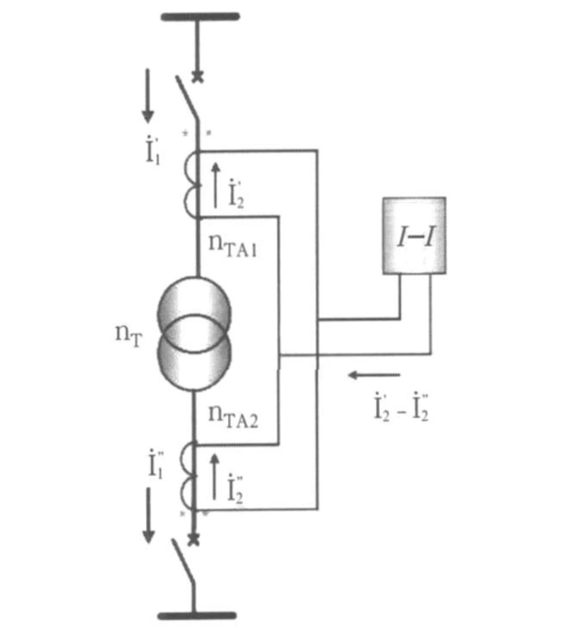
Power Transformer Protection: Schemes, Relays and Protection Functions
Power transformer protection is the coordinated set of electrical, mechanical and thermal functions that detect internal faults, abnormal operating conditions and external faults. Most schemes pair 87T differential with overcurrent and earth-fault backup, then add Buchholz, winding temperature and pressure devices where the transformer is oil-filled.
Written by Leon Zhang, Protection Application Engineer · Technical review by Li Ming, Electrical Engineer · Last reviewed September 2026
The two ends of the range look nothing alike. A 2 MVA dry-type unit in a factory usually needs overcurrent, earth fault and winding temperature monitoring, and nothing more. A 110/33/11 kV three-winding generator step-up transformer needs 87T on all three windings, backup overcurrent per winding, Buchholz, pressure relief and overexcitation.
What Faults and Abnormal Conditions Must the Scheme Cover?
Fault duty decides the scheme. Match each fault type to a function before choosing a relay.
Transformers are subject to various faults and abnormal conditions that require different protection functions for reliable detection and clearance. Understanding these conditions is essential for correct application of protection schemes and rational configuration of transformer protection devices.
Internal Electrical Faults
Internal electrical faults occur within the transformer tank and pose a high risk of damage. These include:
- Phase-to-phase faults – Short circuits between phases within the windings, producing large fault currents
- Phase-to-ground faults – Short circuits between a phase winding and the transformer tank or grounded core
- Winding faults – Electrical breakdown within the winding structure
- Inter-turn faults – Short circuits between turns of the same winding, often producing relatively low fault currents but causing localized overheating
- Bushing faults – Flashover or breakdown of transformer bushings
Internal faults are typically detected by transformer differential protection (87T) and gas/oil protection devices.
External System Faults
External faults occur outside the transformer but still affect its operation. These include:
- Downstream short circuits – Faults on connected feeders or downstream equipment, causing high through-current
- External earth faults – Ground faults on the system outside the transformer zone
- Through-fault current – High fault current flowing through the transformer during external system faults
External faults do not cause differential current but produce high through-current that can stress the transformer and CTs.
Abnormal Operating Conditions
Abnormal operating conditions are not immediate faults but may develop into more serious issues if not addressed:
- Overload – Extended operation above rated capacity, causing excessive temperature rise and insulation aging
- Overexcitation – Excessive voltage/frequency ratio, leading to core saturation and increased magnetizing current
- Overheating – High operating temperatures from overloads, cooling failures or other causes
- Low oil level – Reduced oil level in the tank, exposing winding insulation and reducing cooling
- Gas generation – Gas production due to partial discharges or thermal decomposition of oil and paper insulation
- Abnormal pressure – Pressure build-up within the tank due to internal faults or gas accumulation
Matching Each Fault Type to a Function
Different faults and abnormal conditions require different protection functions to ensure selective and reliable clearance. Internal faults typically require fast tripping, while abnormal conditions may initiate alarms or delayed tripping to allow corrective action. Reasonable matching of transformer protection functions is the core of reliable fault disposal.
Power Transformer Protection Schemes: Main and Backup
A power transformer protection scheme normally combines several transformer protection functions to detect internal faults, external faults, and abnormal operating conditions.
| Protection Function | ANSI | Main Purpose | Typical Application |
|---|---|---|---|
| Differential Protection | 87T | Internal electrical faults | Medium/large transformers |
| Overcurrent | 50/51 | Backup / fault protection | Most transformer schemes |
| Earth Fault | 50N/51N | Ground faults | Grounded systems |
| REF | 64REF / 87N* | Sensitive earth-fault protection | Transformer winding |
| Overload | 49 | Thermal overload | Transformer thermal protection |
| Overexcitation | 24 | V/Hz abnormality | Large transformers |
| Gas / Buchholz | 63 | Internal faults / gas accumulation | Oil-immersed transformers |
| Temperature | 49 | Winding/oil overheating | Oil and dry-type transformers |
| Pressure Relief | 63 | Rapid pressure increase | Oil-immersed transformers |
| Oil Level | 71 | Low oil condition | Oil-immersed transformers |
Transformer Protection Relays: Main and Backup Functions
Main and backup answer different questions. Main protection, normally 87T, clears internal faults with no intentional delay and sees only the zone closed by its CTs. Backup, normally 50/51 or 50N/51N, sits outside that zone, waits a graded time and clears what the main element misses. Both are needed. A scheme with only one has a hole.
The table below lists the usual split of duties.
| Protection | Role |
|---|---|
| 87T Differential | Main electrical protection |
| REF | Sensitive earth-fault protection where applicable |
| Buchholz | Main non-electrical protection for oil-filled transformers |
| 50/51 | Backup / supplementary protection |
| 50N/51N | Earth-fault backup |
| 49 | Thermal monitoring |
| 24 | Overexcitation |
How Main and Backup Share the Clearing Duty
Main protection, such as 87T differential, provides fast and selective clearing for faults within the defined protection zone. Backup protection, such as 50/51 overcurrent, operates with time delays and provides coverage for faults that may not be detected by the main protection or when the main protection fails.
Non-electrical protection, such as Buchholz and thermal monitoring, covers conditions that are not detected by electrical protection, including gas accumulation, low oil level, and overheating.
Application Considerations
The exact combination of protection functions depends on transformer size, voltage level, winding configuration, grounding and applicable standards. Larger and more critical transformers typically require more full protection schemes, while smaller distribution transformers may have simpler arrangements.
Dry-Type Transformer Protection
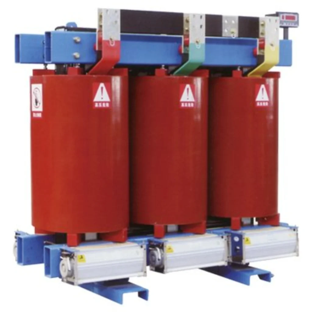
Dry-type transformers lack oil-based protection devices, so protection relies on electrical and thermal monitoring. Commonly applied functions include:
- Overcurrent and short-circuit protection – 50/51 elements for phase and earth faults
- Earth fault protection – Sensitive ground fault detection depending on neutral grounding
- Winding temperature monitoring – Continuous hot-spot monitoring via embedded sensors
- Thermal overload protection – Alarm and trip based on temperature or thermal models
- Fan control – Automatic cooling control based on winding temperature
- Enclosure and interlock protection – Safety monitoring for compartment access and operating sequences
Protection thresholds should follow the transformer manufacturer’s data and project protection study.
Oil-Immersed Transformer Protection
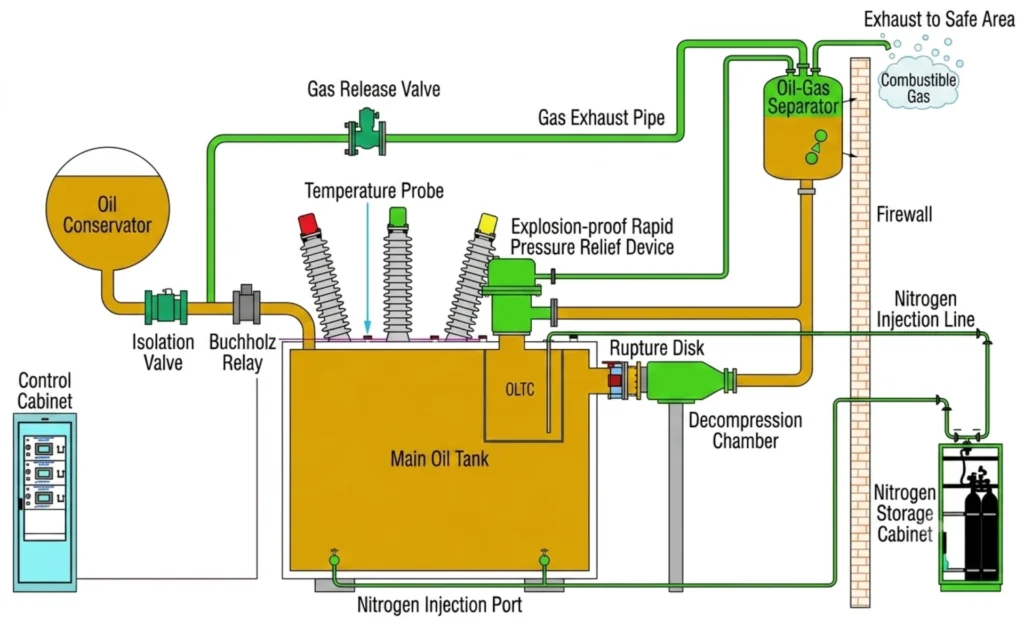
Oil-immersed transformers require a combination of electrical, mechanical and non-electrical protection functions to address a wide range of fault types and operating conditions.
The protection scheme typically includes the following functions.
Electrical Protection
Electrical protection covers faults and abnormal conditions detected through electrical quantities:
- 87T Differential Protection – Main protection for internal winding and terminal faults
- 50/51 Overcurrent Protection – Backup protection for phase faults
- 50N/51N Earth Fault Protection – Backup protection for ground faults
- REF (Restricted Earth Fault) – Sensitive earth-fault protection where applicable
- 24 Overexcitation Protection – Protection against excessive voltage/frequency ratio
- 49 Thermal Overload Protection – Thermal monitoring based on current-derived or direct temperature measurement
Mechanical and Non-Electrical Protection
Mechanical and non-electrical protection covers physical and thermal conditions within the transformer tank:
- Buchholz Relay – Detects gas accumulation and rapid oil movement caused by internal faults
- Pressure Relief Device – Releases excess pressure to prevent tank rupture during internal faults
- Oil Temperature Monitoring – Measures top-oil temperature for thermal monitoring and cooling control
- Winding Temperature Monitoring – Measures or calculates hot-spot temperature for thermal protection
- Oil Level Monitoring – Detects low oil level that may expose windings or impair cooling
- Cooling System Control – Controls cooling fans and pumps based on oil and winding temperature
Application Note:
The exact combination of protection functions depends on transformer size, voltage level, criticality, and applicable project standards.
Larger transformers typically include more full protection schemes.
Transformer Differential Protection (ANSI 87T)
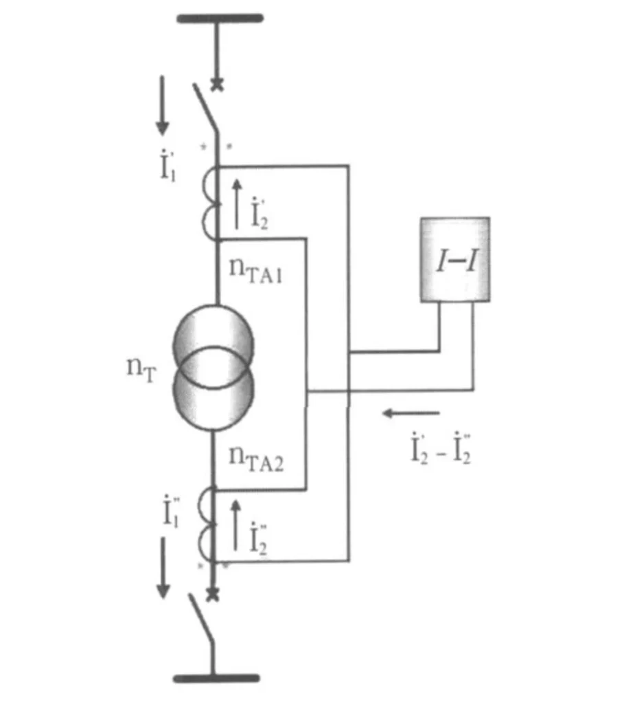
ANSI 87T is the standard designation for transformer differential protection. It is one of the primary transformer protection functions for detecting internal faults within the protected transformer zone.
What Does 87T Protect?
The 87T relay detects internal electrical faults, including:
- Phase-to-phase and phase-to-ground faults
- Winding faults, including inter-turn short circuits
- Internal lead and bushing faults
Why Is 87T the Primary Protection?
The relay operates on the principle of current balance. Under normal and external fault conditions, currents entering and leaving the zone are balanced. When an internal fault occurs, the balance is disrupted and the relay trips. A dedicated 87T differential relay covers only the zone closed by its CTs.
Anything beyond those CTs still needs backup.
To ensure security, the relay uses:
- Percentage restraint – Raises the operating threshold as through-current increases, ensuring stability during external faults
- Harmonic restraint – Uses second harmonic detection to block tripping during transformer energization (inrush)
Position in the Protection Scheme
The 87T relay is the first line of defense, providing fast clearance for internal faults. It is typically supported by backup protection (overcurrent, earth fault), non-electrical protection (Buchholz, temperature, pressure), and thermal monitoring.
For practical application guidance, refer to the following resources:
CT Requirements for Transformer Protection
Proper CT selection is critical to reliable transformer protection, particularly for differential protection and external fault conditions.
| Requirement | Description |
|---|---|
| CT Ratio | Primary rating must match transformer current; secondary rating (1A or 5A) must be compatible with relay inputs |
| Accuracy | High accuracy required for reliable differential protection; class must suit fault level and application |
| Saturation | CTs must have adequate knee-point voltage to maintain performance under maximum fault current |
| Polarity | Correct polarity essential for proper differential calculation; verify during commissioning |
| Burden | CT must drive connected burden (relay + wiring) within rated output |
| Secondary Wiring | Correctly sized to avoid excessive voltage drop and increased burden |
CT requirements should be verified during the protection study and relay application design. For detailed calculation methods, refer to the Differential Protection Relay Setting Calculation guide.
Scheme Examples by Rating and Voltage Class
The following examples show how transformer protection requirements change according to transformer rating, voltage level, winding configuration, and application.
Case 1: Small Industrial Dry-Type Transformer
| Item | Description |
|---|---|
| Typical Rating | 1–5 MVA, 11kV/0.4kV |
| Application | Factory or commercial facility |
| Protection Functions | Overcurrent (50/51), earth fault (50N/51N), winding temperature monitoring, fan control |
| Why | Dry-type transformers have no oil, so non-electrical protection is limited to temperature monitoring. Differential protection is often not applied due to cost and available fault level. |
Case 2: 33/11kV Substation Transformer (Two-Winding)
| Item | Description |
|---|---|
| Typical Rating | 10–30 MVA, 33kV/11kV |
| Application | Distribution substation |
| Protection Functions | 87T differential protection, 50/51 overcurrent (HV and LV), 50N/51N earth fault, Buchholz relay (gas and oil flow), oil temperature monitoring, pressure relief, winding temperature monitoring |
| Why | This is a common configuration for distribution transformers. 87T provides fast main protection for internal faults. Buchholz and temperature devices cover non-electrical faults and abnormal conditions. Overcurrent provides backup protection. |
Case 3: 110/33/11kV Three-Winding GSU Transformer
| Item | Description |
|---|---|
| Typical Rating | 50–200 MVA, 110kV/33kV/11kV |
| Application | Generator step-up (GSU) or transmission substation |
| Protection Functions | Multi-winding 87T differential protection, restricted earth fault (REF), backup overcurrent protection (50/51) on all windings, fault recorder (COMTRADE), IEC 61850 communication with GOOSE and MMS, SCADA integration |
| Why | Large GSU and transmission transformers require full protection. Multi-winding 87T provides differential protection covering all three windings. REF offers sensitive earth fault protection. Communication integration supports substation automation and remote supervision. |
Scheme Examples Are Not a Design Basis
The protection schemes shown above are examples only. Final protection design must be based on transformer manufacturer data, fault studies, system grounding arrangements, relay coordination studies, and applicable project standards.
Always consult a qualified protection engineer for specific applications.
Protection by Transformer Type
| Transformer Type | Typical Protection Considerations |
|---|---|
| Dry-Type Transformer | Overcurrent, earth fault, temperature, thermal protection |
| Oil-Immersed Transformer | 87T, Buchholz, temperature, pressure, oil level, backup protection |
| Two-Winding Transformer | 87T + backup protection |
| Three-Winding Transformer | Multi-side differential + backup protection |
| Generator Step-Up Transformer | 87T + generator/transformer coordinated protection |
| Autotransformer | Differential + REF + backup protection |
| Distribution Transformer | Protection based on rating, voltage and network requirements |
Transformer Protection Functions for Different Applications
Transformer protection requirements vary substantially depending on the application, system configuration, and operational environment.
The following sections describe typical protection considerations for common applications.
Utility Substations
Transformers in utility substations are critical to grid reliability and typically require full protection schemes.
| Feature | Consideration |
|---|---|
| 87T Differential Protection | Main protection for internal transformer faults |
| REF (Restricted Earth Fault) | Sensitive earth fault detection where applicable |
| Buchholz Protection | Gas and oil flow detection for oil-immersed transformers |
| Backup Protection | Overcurrent and earth fault protection (50/51, 50N/51N) |
| SCADA Integration | Remote monitoring and control capability |
| IEC 61850 Communication | GOOSE and MMS for substation automation and interoperability |
Industrial Power Plants
Industrial transformers supply power to manufacturing processes. Protection must minimize downtime and coordinate with plant distribution.
- 87T Differential Protection – Main protection for critical transformers
- REF Protection – Sensitive earth fault detection where applicable
- Overcurrent Protection (50/51) – Backup protection for phase and earth faults
- Thermal Protection – Winding temperature and overload monitoring
- Interlocking – Coordination with process protection and motor control
Solar Power Plants
Solar plants use step-up transformers to connect inverter output to the medium-voltage or high-voltage grid.
Protection must handle variable generation and frequent energization.
- 87T Differential Protection – Main protection for step-up transformers
- Overcurrent Protection (50/51) – Backup and fault protection
- Harmonic Restraint – Important for inverter-generated harmonics
- Frequent Energization Capability – Inrush restraint suitable for daily start/stop operation
Wind Power Plants
Wind farms have multiple step-up transformers, often with collection networks. Protection must coordinate with wind turbine control and grid connection requirements.
- 87T Differential Protection – Main protection for step-up transformers
- Overcurrent and Earth Fault Protection – Backup protection for collection network faults
- Voltage and Frequency Protection – For grid code compliance and islanding detection
- IEC 61850 Communication – For farm-wide monitoring and control
Generator Step-Up Transformers
Generator step-up (GSU) transformers connect generators to the transmission system. Protection must coordinate with generator protection and handle high fault current contributions.
- 87T Differential Protection – Main protection for GSU transformers
- REF Protection – Sensitive earth fault detection on the generator side
- Overcurrent Protection – Backup protection coordinated with generator protection
- Transient Monitoring – For short-circuit stress and high inrush effects
- Trip Coordination – Must interface with generator protection and circuit breakers
Application Lists Open the Design, They Do Not Close It
The protection functions and scheme design depend on transformer rating, voltage level, system grounding, and project-specific requirements. Always refer to the protection study and applicable standards for final scheme design.
How to Select a Power Transformer Protection Relay
Selecting the appropriate relay is only one part of designing a complete transformer protection system. The required protection functions should first be determined from the transformer rating, voltage level, winding configuration, grounding method, and protection requirements. Work through the selection factors below, then check the shortlist against the relay selection criteria.
| Step | Selection Factor | Key Consideration |
|---|---|---|
| 1 | Transformer Rating | MVA rating determines protection scope and fault current capability |
| 2 | Voltage Level | Relay inputs and insulation must suit HV/LV levels |
| 3 | Winding Configuration | Two-winding, three-winding, or auto-transformer support required |
| 4 | Transformer Type | Oil-immersed or dry-type affects non-electrical protection needs |
| 5 | CT Inputs | Check secondary rating (1A/5A), CT sets, and ratio compensation |
| 6 | Protection Functions | Define 87T, 50/51, 50N/51N, REF, thermal, overexcitation (24) as required |
| 7 | Binary I/O | Sufficient I/O for trip, alarm, blocking, and control signals |
| 8 | Communication Protocol | IEC 61850, Modbus, or IEC 60870-5-103 per project/SCADA needs |
| 9 | Fault Recording | COMTRADE waveform capture and SOE for post-event analysis |
| 10 | IEC / Project Standards | Compliance with IEC 60255 and project specifications |
| 11 | Panel Integration | Form factor, mounting, and dimensions must fit panel layout |
| 12 | FAT / SAT Requirements | Confirm factory and site acceptance testing and documentation |
Common Transformer Protection Problems
| Problem | Possible Causes | Recommended Check |
|---|---|---|
| Differential trip during energization | Inrush / protection configuration | Check inrush restraint and settings |
| Differential unbalance | CT ratio/polarity/vector compensation | Verify CT circuit and relay configuration |
| Overtemperature alarm | Sensor/cooling/load | Check sensor and cooling system |
| Earth-fault trip | Internal/external fault or CT issue | Check fault records and protection zone |
| Relay communication failure | Protocol/network configuration | Check address, wiring and protocol |
Transformer Protection – Q&A
Q1. What is power transformer protection?
Power transformer protection is a coordinated system of protection functions used to detect and isolate transformer faults and abnormal operating conditions.These transformer protection functions may include differential, overcurrent, earth-fault, REF, thermal, overexcitation, Buchholz, and pressure protection.
Q2. What protection is required for a power transformer?
Protection requirements depend on transformer size, voltage level, and application. Typical protection includes differential protection (87T), overcurrent protection (50/51), earth fault protection, non-electrical protection (such as Buchholz and temperature monitoring), and backup protection.
Q3. What is the main protection for a power transformer?
The main protection for a power transformer is typically differential protection (ANSI 87T), which provides fast and selective detection of internal electrical faults within the transformer protection zone.
Q4. What is the difference between main and backup transformer protection?
Main protection provides fast, selective clearing for faults within its designated zone. Backup protection operates with time delays and covers faults that may not be detected by the main protection or when the main protection fails.
Q5. What is ANSI 87T transformer differential protection?
ANSI 87T is the standard device number for transformer differential protection. It compares currents entering and leaving the transformer and trips when a differential current indicates an internal fault.
Q6. What protection is used for oil-immersed transformers?
Oil-immersed transformers typically use differential protection (87T), overcurrent and earth fault protection (50/51, 50N/51N), Buchholz relay, oil and winding temperature monitoring, pressure relief, and oil level monitoring.
Q7. What protection is used for dry-type transformers?
Dry-type transformers rely on overcurrent protection (50/51), earth fault protection, winding temperature monitoring, thermal overload protection, fan control, and enclosure/interlock protection, as they do not have oil-based protection devices.
Q8. What protection is required for a three-winding transformer?
A three-winding transformer requires differential protection with CT inputs on all three windings, plus backup overcurrent protection on each winding, and non-electrical protection appropriate for the transformer type.
Q9. What is the role of Buchholz protection?
Buchholz protection detects gas accumulation and rapid oil movement within oil-immersed transformers. It provides alarm for slow gas generation and trip for rapid gas evolution or oil surge caused by internal faults.
Q10. Why is overexcitation protection used for power transformers?
Overexcitation protection (ANSI 24) is used to protect transformers against excessive voltage/frequency ratio (V/Hz), which can cause core saturation, increased magnetizing current, overheating, and possible core or winding damage.
Q11. What should be considered when selecting a transformer protection relay?
Key factors include transformer rating, voltage level, winding configuration, transformer type, CT inputs, required protection functions, binary I/O, communication protocol, fault recording capability, and compliance with project standards.
Q12. Does transformer protection relay support IEC 61850?
Support for IEC 61850 depends on the relay model. Many modern transformer protection relays support IEC 61850, including GOOSE and MMS services, for integration into substation automation systems.
Conclusion
Power transformer protection combines 87T differential with Buchholz, earth-fault, and thermal backup. Match the scheme to transformer size and application, then coordinate settings with upstream protection.
Technical References
| Source | What it covers | Type | Edition |
|---|---|---|---|
| IEEE C37.91 | Guide for protecting power transformers: fault types, scheme selection, CT behaviour during system faults | Guide | 2021 |
| IEC 60255-187-1 | Functional requirements for differential protection of motors, generators and transformers | Standard | 2021 |
| IEC 61869-2 | Instrument transformers: additional requirements for current transformers | Standard | 2012 |
| ANSI/IEEE C37.2 | Device function numbers, acronyms and contact designations (87T, 50/51, 63, 49, 71) | Standard | 2022 |
| IEC 60255-1 | Measuring relays and protection equipment: common requirements | Standard | 2022 |
| IEC 60076-11 | Power transformers: dry-type transformers | Standard | 2018 |
Check each edition against the project specification before issue. Relay makers publish their own application manuals, and those take precedence where a function is implemented in a vendor-specific way.
Related Reading



About Author

Hello, I'm Leno Zhang. I have 15 years of experience in the power relay protection industry with extensive pre-sales and after-sales project experience. Our company specializes in various complete sets of relay protection and automation equipment. I can assist customers in solving all practical on-site project challenges and provide optimal integrated solutions.
Tell Us Your Requirement
High Quality
Stable performance, reliable design, ensuring safe operation for power system protection and grid stability.
Fast Delivery
Timely delivery to support your urgent orders and project schedules efficiently and professionally at any time.
Best Warranty
Professional Warranty: Reliable after-sales support for stable relay protection and long-term customer satisfaction.