

-
Leon Zhang sales consultant
-
Email: zxl635973785@gmail.com
-
Phone/WhatsApp: +86 13655813266
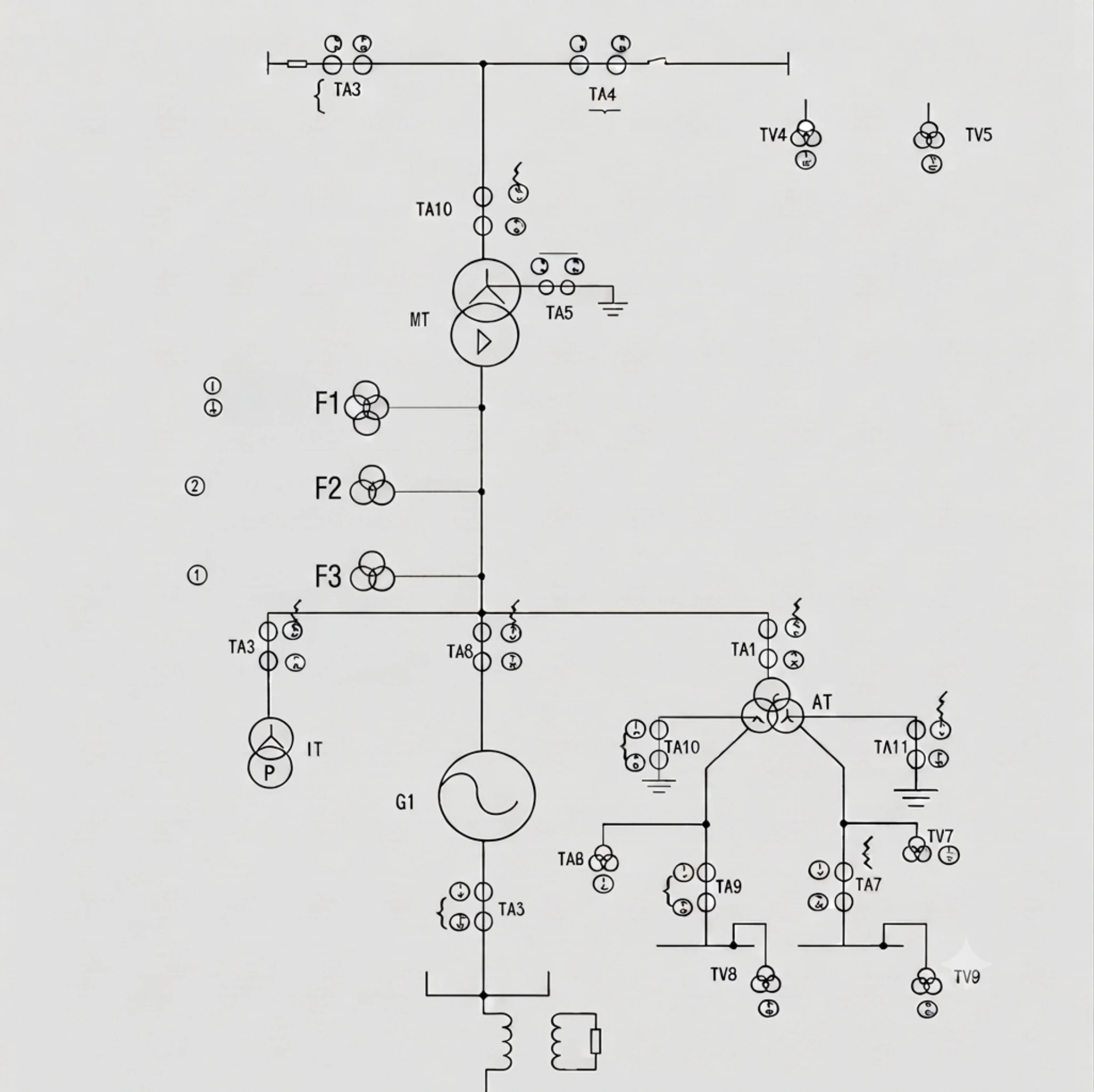
Generator Transformer Unit Protection Scheme for Power Plants
Generator transformer unit protection is a comprehensive protection scheme designed for generator-transformer blocks in power plants. It protects the generator, step-up transformer and connection equipment against internal faults, abnormal operating conditions and external system disturbances.
A generator-transformer unit typically requires coordinated protection functions including differential protection (87GT), overcurrent backup protection, earth fault protection, overexcitation protection and abnormal operation protection.
What Is Generator Transformer Unit Protection?
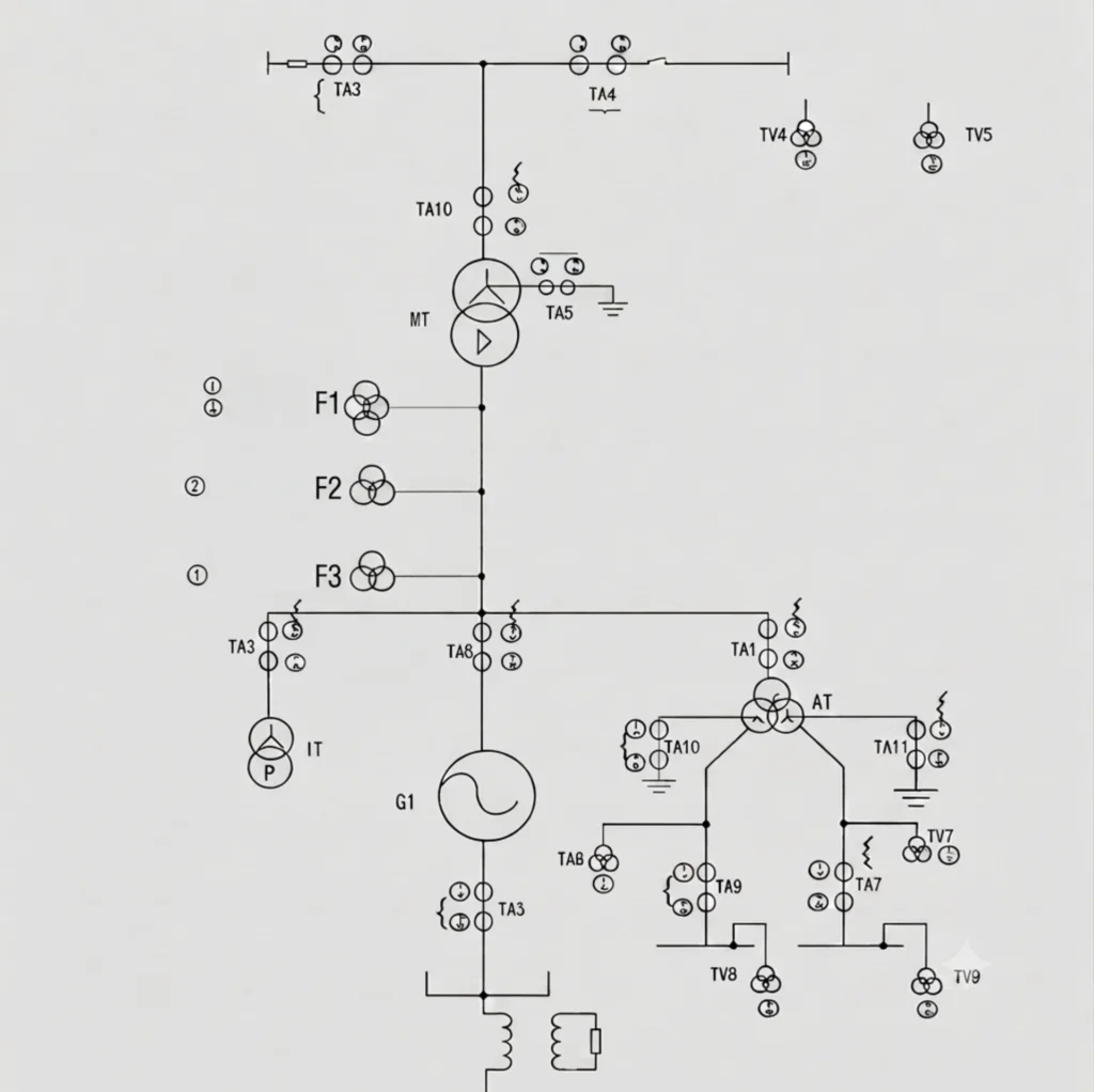
Generator Transformer Unit Protection is an integrated protection scheme designed for a generator and its directly connected step-up transformer, treating them as a single electrical unit.
In most power plants, the generator and transformer are linked without a circuit breaker between them, meaning they share a common electrical zone where a fault on either machine can rapidly affect the other. For example, an internal fault in the transformer will cause the generator to continue feeding current into the fault, while a generator fault can stress the transformer windings and damage its core. Additionally, the connection zone between the two machines—such as busducts or cables—is not covered by standalone generator or transformer protection.
By applying coordinated unit protection, typically through an 87GT relay that combines generator differential (87G) and transformer differential (87T) functions, any fault within this interconnected system can be detected and cleared with a single, simultaneous trip command. This unified approach ensures comprehensive protection, prevents cascading damage, reduces plant downtime, and safeguards the substantial capital investment represented by both critical assets.
Generator Transformer Protection Functions
| ANSI Code | Protection Function | Purpose |
|---|---|---|
| 87GT | Generator Transformer Differential | Internal fault protection |
| 50/51 | Overcurrent Protection | Backup protection |
| 64 | Earth Fault Protection | Ground fault detection |
| 24 | Overexcitation | V/Hz protection |
| 49 | Thermal Protection | Overheating protection |
| 32 | Reverse Power | Generator motoring |
| 40 | Loss of Excitation | Field failure |
Brief Function Descriptions
| ANSI Code | Function | Description |
|---|---|---|
| 87GT | Generator Transformer Differential | Compares currents on both sides of the generator and transformer windings. Any significant difference indicates an internal fault, triggering an instantaneous trip. This is the primary protection for the generator-transformer unit. |
| 50/51 | Overcurrent Protection | Provides backup protection for external faults and overloads. 50 is instantaneous for severe short circuits; 51 is time-delayed for coordination with downstream protections. |
| 64 | Earth Fault Protection | Detects ground faults in the generator stator or transformer windings. Early detection prevents escalation to phase-to-phase faults and major equipment damage. |
| 24 | Overexcitation | Monitors the V/Hz ratio to prevent core saturation in both the generator and transformer. Excessive V/Hz causes rapid heating and can damage the iron core. |
| 49 | Thermal Protection | Monitors winding and core temperatures using thermal models or direct RTD inputs. Prevents insulation degradation and extends equipment life by tripping or alarming before overheating occurs. |
| 32 | Reverse Power | Detects power flow reversal, indicating the generator is motoring due to prime mover failure. Protects turbines and gearboxes from mechanical damage. |
| 40 | Loss of Excitation | Detects excitation system failure. Loss of field causes the generator to draw reactive power from the grid, leading to voltage instability and rotor overheating. |
Protection Tiers for Generator Transformer Units
| Protection Level | Functions Included | Best For |
|---|---|---|
| Basic | 50/51 + 64 | Small or non-critical units |
| Standard | 50/51 + 64 + 87GT | Most industrial applications |
| Comprehensive | 87GT + 50/51 + 64 + 24 + 49 + 32 + 40 | Large, utility-critical units |
How Generator Transformer Unit Protection Works
Generator Transformer Unit Protection operates on the current balance principle. The relay continuously compares currents measured by CTs on both sides of the protected zone to determine whether the system is healthy or faulted.
Normal Condition
| Aspect | Status |
|---|---|
| Generator side CT | Measures normal current |
| Transformer side CT | Measures equal current |
| Differential current | ≈ 0 |
| Relay action | No trip – normal operation continues |
Under normal conditions, the current entering the transformer equals the current leaving the generator. The differential current is near zero, and the relay remains inactive.
Internal Fault
When an internal fault occurs within the protected zone (generator windings, transformer windings, or connection zone), the current balance is broken.
| Aspect | Status |
|---|---|
| Generator side CT | High fault current |
| Transformer side CT | Mismatched current |
| Differential current | Exceeds threshold |
| Relay action | Trip circuit breakers |
Common Internal Faults:
- Winding short circuit
- Phase fault (phase-to-phase or three-phase)
- Insulation failure (ground or phase faults)
Relay Response:
The fault current flows only within the protected zone, creating a significant differential current. The relay detects this imbalance and issues a simultaneous trip command to both the generator breaker and the transformer high-voltage breaker, isolating the entire unit from the grid within milliseconds.
Summary Table
| Condition | Generator CT | Transformer CT | Differential Current | Relay Action |
|---|---|---|---|---|
| Normal | Normal | Equal | ≈ 0 | No trip |
| Internal Fault | High fault | Mismatched | > Threshold | Trip both breakers |
This simple yet effective principle—comparing currents at both ends of the protected zone—ensures fast fault detection, minimizes damage, and protects both generator and transformer assets.
Applications of Generator Transformer Unit Protection
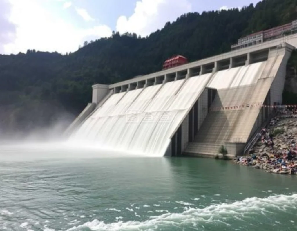
Generator Transformer Unit Protection is essential across all power generation applications where generators are directly connected to step-up transformers without a breaker between them.
Hydropower Plant
| Aspect | Description |
|---|---|
| Typical Capacity | 1MW – 800MW+ |
| Key Protection Focus | 87GT, 32, 81, 40, 24 |
| Why Needed | Frequent start/stop cycles, over-speeding risks, water flow variations affect both generator and transformer |
Thermal Power Plant
| Aspect | Description |
|---|---|
| Typical Capacity | 100MW – 1000MW+ |
| Key Protection Focus | 87GT, 50/51, 64, 49, 24, 40, 32 |
| Why Needed | Continuous high-load operation, large fault currents, critical grid interconnection requiring high reliability |
Gas Power Plant
| Aspect | Description |
|---|---|
| Typical Capacity | 10MW – 400MW |
| Key Protection Focus | 87GT, 50/51, 81, 24, 40, 32 |
| Why Needed | Rapid start/stop cycles, high sensitivity to frequency deviations, fast fault clearance required |
Industrial Power Generation
| Aspect | Description |
|---|---|
| Typical Capacity | 1MW – 100MW |
| Key Protection Focus | 87GT, 50/51, 64, 32, 27/59, 81 |
| Why Needed | Continuous production depends on reliable power; faults can halt entire production lines |
Summary Table
| Application | Capacity | Voltage | Key Functions |
|---|---|---|---|
| Hydropower | 1–800MW | 400V–13.8kV | 87GT, 32, 81, 40, 24 |
| Thermal | 100–1000MW+ | 11kV–24kV | 87GT, 50/51, 64, 49, 24, 40, 32 |
| Gas | 10–400MW | 6.6kV–13.8kV | 87GT, 50/51, 81, 24, 40, 32 |
| Industrial | 1–100MW | 400V–11kV | 87GT, 50/51, 64, 32, 27/59, 81 |
Why Unit Protection is Critical Across All Applications
- Protects generator, transformer, and connection zone
- Single trip command clears faults fast
- Prevents fault propagation between machines
- Reduces downtime and protects capital investment
Difference Between 87G, 87GT and 87T Protection
Although generator protection and generator transformer protection sound similar in name, they differ fundamentally in protection scope and protected equipment.
| Protection | Protected Equipment | Scope of Protection |
|---|---|---|
| 87G | Generator stator | Internal stator winding faults only |
| 87T | Transformer | Transformer winding faults only |
| 87GT | Generator-transformer unit | Generator + step-up transformer + connection zone |
87G – Generator Protection
87G (Generator Differential Protection) is the primary protection for the generator. It compares currents measured by CTs on the neutral side and line side of the generator stator windings to detect internal phase-to-phase faults. Its protection scope is limited to the generator itself, covering the stator winding zone between the neutral CT and the line CT. When an internal fault is detected, 87G issues an immediate trip command, disconnecting only the generator from the system.
Typical Application: Standalone generators, or as the primary protection for the generator within a generator-transformer unit.
👉 [Learn more about 87G Generator Differential Protection Relay →]87G
87T – Transformer Protection
87T (Transformer Differential Protection) is specifically designed to protect the transformer itself. It compares currents measured by CTs on the high-voltage and low-voltage sides of the transformer to detect internal winding faults. Its protection scope is limited to the transformer tank interior and does not cover the generator or the connection zone between them.
👉 [Learn more about 87T Transformer Differential Protection Relay →]87T
87GT – Generator Transformer Unit Protection
87GT (Generator Transformer Differential Protection) adopts a holistic protection approach, treating the generator, generator step-up transformer (GSU), and the connection zone between them as a single unified protection unit. Since there is typically no circuit breaker between the generator and the step-up transformer, they are electrically directly connected and share a common electrical zone. A fault in either machine will rapidly affect the other, requiring coordinated and unified protection.
87GT protection compares currents from CTs on the generator line side, the transformer high-voltage side, and the transformer neutral point. This provides comprehensive coverage of the generator, transformer, and the connection zone between them. Any differential current indicates an internal fault within the unit, triggering a simultaneous trip command that disconnects the entire generator-transformer unit from the grid. This coordinated approach forms the core of an effective Generator Transformer Protection System, ensuring that all components within the unit are safeguarded against internal faults.
Typical Application: Generator-transformer units in hydro, thermal, and gas power plants.
👉 [Learn more about 87GT Generator Transformer Protection Relay →]87GT
Why Do We Need to Distinguish Between Them?
| Protection Type | Protection Scope | Fault Response |
|---|---|---|
| 87G | Generator only | Trips only the generator |
| 87T | Transformer only | Trips only the transformer |
| 87GT | Generator + Step-up transformer + Connection zone | Trips both generator and transformer simultaneously |
The key difference is: 87G protects an isolated piece of equipment, while 87GT protects the complete generator-transformer unit. Because there is no circuit breaker separating the generator and transformer within the unit, any internal fault requires simultaneous isolation of both machines—and this is precisely the core value of 87GT protection. For plant operators, implementing dedicated Generator Step Up Transformer Protection is essential to secure the critical link between generation and transmission.
Related Generator Transformer Protection Products
For comprehensive protection of generator-transformer units, we offer the following key products:
87GT Generator Transformer Protection Relay
The 87GT Generator Transformer Protection Relay is specifically designed for generator-transformer units, providing integrated differential protection that covers the generator, step-up transformer, and the connection zone between them. This relay combines generator differential (87G) and transformer differential (87T) functions with harmonic restraint to prevent tripping on transformer inrush current, making it the ideal choice for hydro, thermal, and gas power plants.
Generator Protection Relay
For standalone generator applications or as the generator-specific component within a unit protection scheme, our Generator Protection Relays deliver comprehensive protection including 87G differential, overcurrent (50/51), loss of excitation (40), reverse power (32), and negative sequence protection (46), suitable for a wide range of generator applications.
👉 Learn more about Generator Protection Relay →
Generator Protection Relay Solution
From small diesel generators to large utility-scale turbines, our Generator Protection Relay Solutions deliver end-to-end engineering services including relay setting assistance, protection scheme design, and SCADA communication configuration, ensuring your critical generation assets remain reliably protected.
👉 Explore Generator Protection Relay Solutions →
Commissioning & Testing Complete Guide
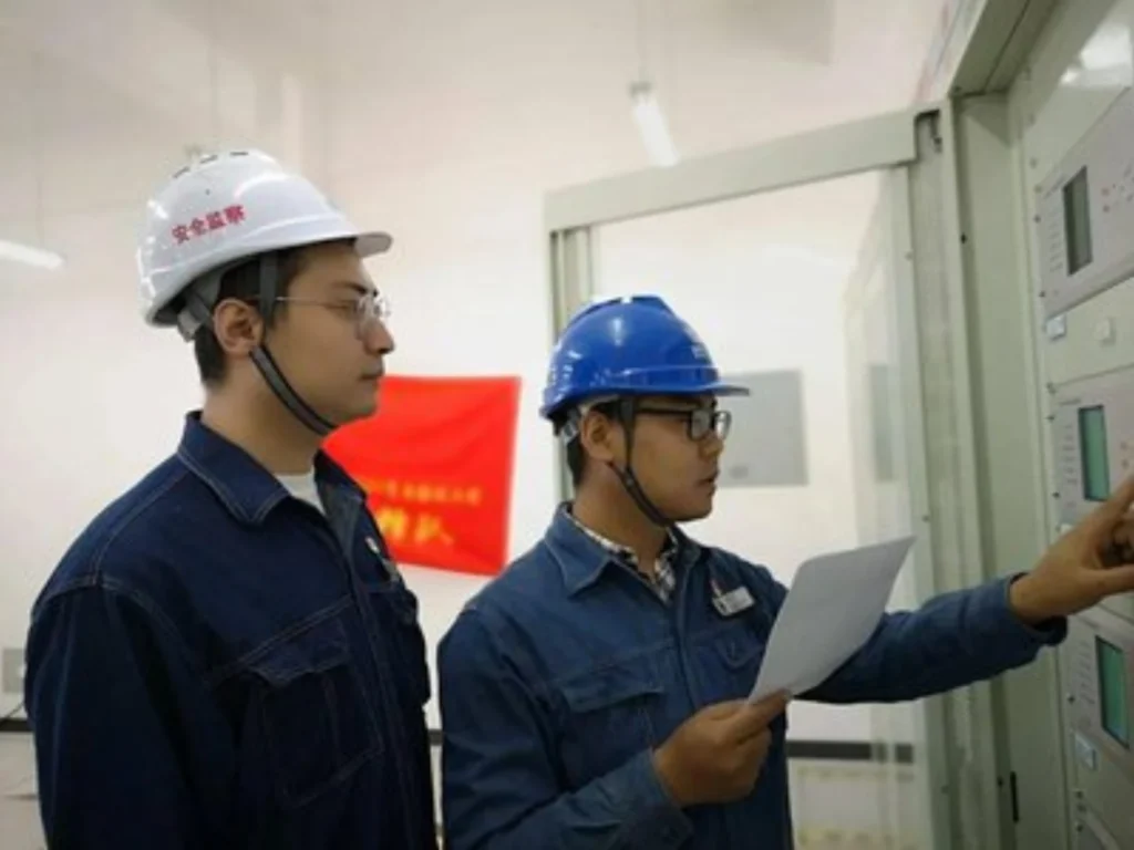
Standard commissioning and testing are the guarantee of long-term stable operation of the relay. The whole process covers pre-operation inspection and professional testing:
Pre-Commissioning Checklist
- Check CT/VT wiring polarity and ratio consistency
- Verify the accuracy of all protection parameter settings
- Test communication connection and alarm signal output
Core Testing Items
- Secondary Injection Test: Simulate various fault signals to verify relay action accuracy
- Primary Injection Test: On-load test to check actual protection operation effect
- End-to-End Test: Verify linkage between relay and breaker trip circuit
FAT (Factory Acceptance Test) and SAT (Site Acceptance Test) must be completed before project delivery to ensure zero fault operation.
Generator Transformer Unit Protection – FAQ
Q1: What is generator transformer unit protection?
A: An integrated protection scheme that treats the generator, step-up transformer, and connection zone as a single unit. Since no circuit breaker separates them, a fault anywhere requires simultaneous tripping of both machines, typically via an 87GT relay.
Q2: What is the purpose of 87GT protection?
A: To provide primary high-speed protection for the entire generator-transformer unit by detecting internal faults and issuing a simultaneous trip command to both breakers, preventing fault propagation and minimizing damage.
Q3: What is the difference between 87G and 87GT?
| 87G | 87GT | |
|---|---|---|
| Protects | Generator only | Generator + Transformer + Connection zone |
| Trip | Generator only | Both generator and transformer |
Q4: What protection functions are required for generator transformer units?
A: Key functions include:
| Function | ANSI | Purpose |
|---|---|---|
| Differential | 87GT | Primary internal fault protection |
| Overcurrent | 50/51 | Backup protection |
| Earth Fault | 64 | Ground fault detection |
| Overexcitation | 24 | V/Hz protection |
| Thermal | 49 | Overheating protection |
| Reverse Power | 32 | Prevents motoring |
| Loss of Excitation | 40 | Excitation failure detection |
Q5: Where is generator transformer unit protection used?
A: In hydro, thermal, gas, and industrial power plants where generators are directly connected to step-up transformers.
Q6: How does Generator Step Up Transformer Protection work?
A: Operates on the current balance principle:
| Condition | CT Readings | Differential Current | Relay Action |
|---|---|---|---|
| Normal | Equal | ≈ 0 | No trip |
| Internal Fault | Unequal | > Threshold | Trip both breakers |
Internal faults include winding short circuits, phase faults, and insulation failure.
Conclusion
The safe operation of power generation equipment relies on accurate fault prediction and rapid response to various risks. 87GT Protection enables sensitive detection of internal faults by comparing currents on both sides of the generator-transformer unit. A well-designed generator transformer protection scheme not only safeguards the security of critical assets but also upholds the long-term value of reliable and continuous power delivery.
For the selection of transformer protection relays, please refer to the relevant selection content.



About Author

Hello, I'm Leno Zhang. I have 15 years of experience in the power relay protection industry with extensive pre-sales and after-sales project experience. Our company specializes in various complete sets of relay protection and automation equipment. I can assist customers in solving all practical on-site project challenges and provide optimal integrated solutions.
Tell Us Your Requirement
High Quality
Stable performance, reliable design, ensuring safe operation for power system protection and grid stability.
Fast Delivery
Timely delivery to support your urgent orders and project schedules efficiently and professionally at any time.
Best Warranty
Professional Warranty: Reliable after-sales support for stable relay protection and long-term customer satisfaction.