Contact Form Demo

87GT Generator Transformer Protection Relay

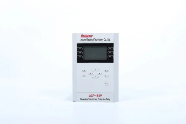
The 87GT generator-transformer protection relay is equipped with a differential protection scheme and specially developed for generator-transformer units. It is applicable to medium and small generator-transformer units with a capacity of no more than 10 MW and realizes the overall differential protection of the complete generator-transformer unit.

Send your requirements, we will quote for you within 12 hours​
TEL: +86 13655813266
Whatsapp: +86 13655813266
zxl635973785@gmail.com

Description

Table of Contents

What Is a Generator Transformer Protection Relay?

A Generator Transformer Protection Relay is a dedicated protection device used to safeguard the generator step-up transformer that connects the generator to the transmission or distribution network.

The relay provides comprehensive protection against internal faults (winding short circuits, core faults, turn-to-turn faults), external system disturbances, and abnormal operating conditions (overload, overexcitation, through-faults), ensuring fast fault clearing to prevent equipment damage.

It typically integrates multiple protection functions, with 87GT differential protection as the primary element, supplemented by overcurrent, earth fault, and thermal overload protection.

In summary, the relay ensures safe and reliable transformer operation, reducing the risk of equipment damage and unplanned outages.

What Is 87GT Protection?

87GT is the ANSI device number commonly used for generator-transformer differential protection (also referred to as overall differential protection).

This protection compares currents on the generator side and the transformer high-voltage side to detect internal faults within the protection zone. When an internal fault occurs, the differential current becomes unbalanced, and the relay issues a trip command to isolate the transformer.

Protection Zone:

  • Generator step-up (GSU) transformer

  • Generator bus duct / isolated phase bus

  • Associated circuit breaker and connecting components

Key Features:

  • High-speed fault clearance

  • High sensitivity to internal winding faults

  • Harmonic restraint to prevent misoperation during inrush current

  • Good selectivity between internal and external faults

Note: The exact protection zone and implementation of 87GT may vary by project and manufacturer. The actual protection scheme should always be consulted.

How Does 87GT Generator Transformer Differential Protection Work?

The differential protection of generator transformer unit continuously monitors current on both sides of the generator-transformer unit.:

  • Generator side current (Input)
  • Transformer side current (Output)

Differential Protection Operating Characteristic Curve

Normal Operation (No Fault)

Under normal operating conditions, the current measured by the generator-side CT and the transformer-side CT are nearly equal (taking into account the transformer turns ratio and vector group correction). The 87GT relay calculates the differential current as the vector difference between these two currents. In a healthy system, the differential current is close to zero (only a small magnetizing current is present), and the relay remains stable.

Internal Fault (Fault Inside the Transformer)

When a fault occurs inside the generator transformer (e.g., winding short circuit, core fault, or turn-to-turn fault), the fault current is supplied from both sides. The current entering from the generator side and the current leaving from the transformer side are no longer balanced. The differential current increases significantly. Once the differential current exceeds the preset threshold, the 87GT relay operates and issues a trip command to isolate the transformer from the system.

External Fault or Through-Fault (Fault Outside the Protected Zone)

When a fault occurs on the system side (outside the transformer), a large fault current flows through the transformer from the generator side to the transformer side. Both CTs measure high but balanced currents. The differential current remains near zero, and the 87GT relay restrains (does not operate). This ensures selective tripping of downstream protection without tripping the generator transformer.

Transformer Energization (Inrush Current)

When the transformer is energized, a high magnetizing inrush current flows into the transformer from the generator side. This current contains a significant second-harmonic component. The 87GT relay includes harmonic restraint logic that detects this second-harmonic content and blocks tripping during inrush conditions, preventing false operation.

Summary of Operating Logic:

Condition Generator-side CT Transformer-side CT Differential Current Relay Response
Normal operation Balanced Balanced Near zero Restrain
Internal transformer fault High current (fault supplied) High current (fault supplied) High Trip
External fault (through-fault) High current (through) High current (through) Near zero Restrain
Transformer energization (inrush) High current (inrush) Low current (unloaded) High (but with 2nd harmonic) Restrain (harmonic restraint)

In summary, the 87GT relay compares the currents at the two ends of the generator transformer. Under normal and external fault conditions, the currents remain balanced and the relay restrains. Under internal fault conditions, the imbalance triggers the relay to operate, ensuring fast and selective fault clearance.

What Does 87GT Protect?

87GT protection covers the generator-transformer unit, providing overall differential protection for the zone from the generator terminals to the transformer high-voltage terminals, as defined by CT locations on both sides.

Typical Protected Zone:

  • Generator terminals

  • Generator bus duct / isolated phase bus

  • Generator step-up (GSU) transformer

  • Transformer high-voltage side (up to HV terminals or associated breaker)

Protection Zone Definition:

  • Generator-side CTs define the start of the zone

  • Transformer-side CTs define the end of the zone

  • All equipment between these CTs is protected

Note: The exact protection boundary may vary by system configuration and CT arrangement. In our application, 87GT protects the generator-transformer unit from the generator side to the transformer side.

87GT vs 87T vs 87G

Protection Protected Equipment Main Purpose
87G Generator Generator differential protection
87T Power Transformer Transformer differential protection
87GT Generator-transformer unit Generator-transformer differential / overall protection

87GT Generator Transformer Protection Functions

The 87GT generator transformer protection relay integrates multiple protection functions to ensure comprehensive coverage for the generator-transformer unit. The key functions are listed below, with the most critical ones presented first.

Generator Transformer Differential Protection – 87GT

This is the primary protection element for the generator-transformer unit. It continuously compares currents on the generator side and the transformer side. When an internal fault occurs, the differential current rises above the preset threshold, and the relay issues a fast trip command to isolate the transformer. This provides high-speed, sensitive protection for winding short circuits, core faults, and turn-to-turn faults.

Percentage Biased Differential Protection

This function enhances the differential protection by providing bias (restraint) based on the through-current magnitude. During external faults or heavy load conditions, the high through-current may cause CT saturation or ratio errors. The percentage bias characteristic increases the trip threshold as the through-current increases, ensuring stability during external faults while maintaining high sensitivity for internal faults.

2nd Harmonic Restraint

During transformer energization, a large magnetizing inrush current flows into the transformer. This inrush current contains a significant second-harmonic component. The 2nd harmonic restraint function detects this harmonic content and blocks tripping during inrush conditions. This prevents the differential relay from misoperating when the transformer is energized, ensuring reliable operation without false trips.

CT Broken Circuit Detection

Current transformer circuits may experience open-circuit conditions due to wiring issues or CT failure. CT broken circuit detection continuously monitors the CT circuits and raises an alarm when a broken circuit is detected. This prevents the differential relay from operating incorrectly due to unbalanced currents caused by CT open circuits, and alerts operators for timely maintenance.

Backup Overcurrent Protection

This function provides backup protection for the generator transformer in case the primary differential protection fails to operate. It includes definite-time and inverse-time overcurrent elements, protecting against phase-to-phase faults and overload conditions. It serves as a reliable backup to ensure fault clearance even if the main protection is unavailable.

Earth Fault Protection

Earth fault protection detects ground faults in the transformer winding or associated connections. It is typically implemented as sensitive earth fault protection using residual current measurement (core balance CT or neutral CT), providing fast detection and clearance of earth faults. This function protects the transformer against single-phase-to-ground faults and reduces the risk of core damage.

Generator Transformer Temperature Protection

This function monitors transformer winding temperature and oil temperature (for oil-filled transformers) using PT100 sensors or other temperature measurement devices. When temperature exceeds preset alarm or trip thresholds, the relay issues an alarm or initiates a trip command to prevent thermal overload damage. This function protects the transformer insulation from accelerated aging caused by excessive temperature and extends transformer service life.

Percentage Differential Protection for Generator Transformers

87GT Generator Transformer Differential Protection Working Principle

Percentage-biased differential protection enhances standard differential protection by improving stability during external faults and CT errors while maintaining high sensitivity to internal faults.

How It Works

The relay calculates both differential current (vector difference) and through-current (restraining current). When through-current is low, the trip threshold is low for high sensitivity. When through-current is high, the threshold increases via the bias slope, preventing false tripping due to CT saturation or errors.

Key Performance Factors

Factor Importance
Adjustable multi-slope bias Matches protection to transformer and CT characteristics
CT saturation stability Prevents false tripping during external faults
2nd harmonic restraint Blocks tripping during transformer inrush current
Overexcitation detection (5th harmonic) Restrains tripping during overexcitation
High sensitivity Detects low-magnitude internal faults

Why Percentage Differential Protection Is Preferred

  • Stable during external faults and through-faults

  • Sensitive to internal winding faults

  • Compensates for CT ratio errors and saturation

  • Reliable during transformer energization (inrush blocking)

Summary

Percentage differential protection is the core protection for generator transformers, offering an optimal balance between sensitivity and stability, with multi-slope characteristics, harmonic restraint, and CT saturation immunity.

Key Considerations When Applying 87GT Protection

When applying 87GT generator transformer differential protection, several technical factors must be carefully considered to ensure reliable, stable, and sensitive operation. The following are the most important considerations for successful implementation.

CT Ratio Matching

The current transformers on the generator side and transformer side often have different ratios due to the voltage transformation. The relay must compensate for these ratio differences to ensure that the currents are balanced during normal operation. This is typically achieved through software settings within the relay or by using interposing CTs. Correct CT ratio matching ensures that the differential current remains near zero under healthy conditions.

CT Saturation

During high current events such as external faults, CTs may saturate, causing distorted secondary currents that can lead to false differential currents. The protection relay must be designed to remain stable during CT saturation. Percentage biased differential protection and transient blocking features help mitigate this risk, ensuring the relay does not misoperate during external faults even if CT saturation occurs.

Transformer Ratio Compensation

The generator transformer has a turns ratio that steps up the voltage from the generator level to the transmission level. The relay must compensate for this ratio to correctly compare primary currents on both sides. Compensation settings are configured based on the transformer nameplate data, ensuring accurate current balancing during normal operation.

Phase Shift Compensation

Generator transformers typically have a vector group that introduces a phase shift between the primary and secondary windings (e.g., YNd1, YNd11). This phase shift must be compensated in the relay logic to correctly align the currents for comparison. Without proper phase shift compensation, the relay would see a standing differential current under normal load conditions, leading to misoperation.

Magnetizing Inrush Restraint

When the transformer is energized, a large magnetizing inrush current flows into the transformer. This current contains a high second harmonic component. The relay must include harmonic restraint (2nd harmonic blocking) to prevent tripping during inrush conditions. This ensures the protection remains secure during transformer energization and does not cause unnecessary outages.

Differential Protection Bias/Slope

The bias characteristic (slope) of the differential protection determines the stability of the relay during external faults and CT saturation. An appropriate bias slope must be selected based on the transformer characteristics, CT performance, and system conditions. Typical settings include minimum pickup, slope 1, and slope 2 (or more), providing an optimal balance between sensitivity and stability.

Summary

Consideration Key Action
CT Ratio Matching Compensate ratio differences to balance currents
CT Saturation Apply percentage bias and transient blocking
Transformer Ratio Compensation Set based on transformer nameplate data
Phase Shift Compensation Correct for transformer vector group
Magnetizing Inrush Restraint Enable 2nd harmonic blocking
Differential Protection Bias/Slope Select appropriate slope settings for stability/sensitivity balance

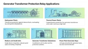
Generator Transformer Protection Relay Applications

Generator Transformer Protection Relay Applications

The 87GT generator transformer protection relay is widely applied across various power generation configurations where a generator is connected to the grid via a step-up transformer. The following are the key application areas.

Hydropower Plants

In hydroelectric power plants, generators are often connected to the transmission network through step-up transformers. The generator transformer protection relay provides reliable protection for the transformer against internal faults, overloading, and system disturbances, ensuring continuous and stable power generation. Its high sensitivity and inrush restraint are particularly valuable in hydro applications where transformers may be frequently energized and de-energized.

Thermal Power Plants

Thermal power plants typically employ large-capacity generators and transformers operating under continuous high load. The 87GT protection relay ensures comprehensive protection for the generator transformer unit, covering winding faults, earth faults, and thermal overload. Its robust performance under high fault current conditions and CT saturation makes it well suited for thermal power plant environments.

Medium and Small Generator-Transformer Units

For medium and small generator-transformer units (e.g., industrial generators, distributed generation, and small utility plants), the protection relay provides cost-effective yet comprehensive protection. It integrates multiple protection functions into a single device, reducing panel space and wiring complexity while ensuring reliable transformer protection.

Generator Transformer Substations

In substations where generator transformers connect the generating plant to the high-voltage grid, the protection relay serves as a critical protection element. It coordinates with other substation protection schemes (e.g., busbar protection, line protection) to ensure selective fault clearance and system stability.

Power Plant Generator Bays

Within the generator bay of a power plant, the generator transformer protection relay is installed as part of the overall generator protection system. It provides unit-type protection for the generator-transformer combination, covering the generator leads, bus duct, and the transformer itself. This centralized protection approach simplifies coordination and ensures fast fault clearing for the entire generator bay.

How to Select a Generator Transformer Protection Relay

Selecting the right generator transformer protection relay requires careful evaluation of technical parameters, protection requirements, and system integration needs. Key factors to consider:

Selection Factor Considerations
Generator Capacity Determines required sensitivity and fault current handling (MVA/MW)
Generator Voltage CT ratio selection and relay voltage compatibility (e.g., 11kV, 13.8kV)
Transformer Voltage Ratio Ratio compensation settings (e.g., 11/220kV, 15.75/400kV)
CT Ratios Must ensure adequate secondary currents under normal and fault conditions
CT Class Accuracy class and saturation immunity (e.g., C200, 5P20)
Transformer Vector Group Phase shift compensation (e.g., YNd1, YNd11)
Protection Zone Define whether it covers generator leads, transformer, or entire unit
Differential Protection Slope Select minimum pickup, slope 1 and slope 2 based on transformer/CT characteristics
Harmonic Restraint 2nd harmonic for inrush blocking; 5th harmonic for overexcitation (if required)
Communication Protocol IEC 61850, Modbus, IEC 60870-5-103/104, DNP 3.0
SCADA Integration Remote monitoring, alarm management, and control capability

CTA:

Contact us for 87GT relay selection and protection setting support. Our engineering team can help you choose the right relay and configure settings for your specific application.

Our 87GT Protection Features

Serial No. Protection Function ANSI Code
1 Instantaneous Differential Protection 87
2 Percentage Differential Protection 87T/87GT
3 2nd Harmonic Restraint 87 Restraint
4 CT Broken Circuit Block for Percentage Differential 60CT interlock 87
5 CT Broken Circuit Alarm 60CT
6 Differential Overcurrent Alarm 87 Alarm
7 Stage I Phase Overcurrent 51P
8 Stage I Overcurrent with Undervoltage Block 51P/27
9 Stage I Overcurrent with Negative Sequence Block 51P/46
10 Stage II Phase Overcurrent 51P
11 Stage II Overcurrent with Undervoltage Block 51P/27
12 Stage II Overcurrent with Negative Sequence Block 51P/46
13 Stage III Phase Overcurrent 51P
14 Stage III Overcurrent with Undervoltage Block 51P/27
15 Stage III Overcurrent with Negative Sequence Block 51P/46
16 Inverse Time Overcurrent 51
17 Inverse Time Overcurrent with Undervoltage Block 51/27
18 Inverse Time Overcurrent with Negative Sequence Block 51/46
19 Overload Protection 49
20 Stage I Negative Sequence Overcurrent 46
21 Stage II Negative Sequence Overcurrent 46
22 Stage I Zero Sequence Overcurrent 51N
23 Stage I Self-produced Zero Sequence Overcurrent 51N
24 Stage II Zero Sequence Overcurrent 51N
25 Stage II Self-produced Zero Sequence Overcurrent 51N
26 Stage III Zero Sequence Overcurrent 51N
27 Stage III Self-produced Zero Sequence Overcurrent 51N
28 Zero Sequence Overcurrent Blocked by Zero Voltage 51N/59N
29 Overvoltage Protection 59
30 Undervoltage Protection 27
31 Zero Sequence Overvoltage Protection 59N
32 PT Broken Circuit Detection 60VT
33 Current Protection Tripped on PT Breakage 60VT interlock 51
34 Undervoltage Protection Blocked on PT Breakage 60VT interlock 27
35 Control Circuit Break Alarm 74TC
36 System Loss of Voltage 27
37 Main Transformer Cabinet Door Open Alarm 74
38 Load Control Function 90
39 Light Gas Alarm 74 Gas Alarm
40 Heavy Gas Trip Protection 74 Gas Trip
41 Temperature Rise Alarm 49T
42 Excessive Temperature Trip 49T
43 Thermal & Cooling System Fault Alarm 74 Cooling Fault
44 Excitation System Fault Protection 40
45 General Electrical Fault Alarm 74 General Fault

FAQ

Q1. What is a Generator Transformer Protection Relay?

A Generator Transformer Protection Relay is a dedicated protection device that safeguards the generator step-up transformer against internal faults, external disturbances, and abnormal operating conditions. It typically integrates differential protection (87GT) as the primary element, along with backup functions such as overcurrent, earth fault, and thermal protection, ensuring fast fault clearance and reliable transformer operation.

Q2. What is 87GT protection?

87GT is the ANSI device number commonly used for generator-transformer differential protection (also referred to as overall differential protection). It compares currents on the generator side and the transformer side to detect internal faults within the protected zone. When the differential current exceeds the preset threshold, the relay issues a trip command to isolate the transformer from the system.

Q3. What does 87GT protect?

87GT protects the generator-transformer unit, covering the zone from the generator terminals to the transformer high-voltage terminals. The protected zone is defined by CT locations on both sides and typically includes the generator bus duct, the step-up transformer, and associated connections. The exact boundary may vary based on system configuration and CT placement.

Q4. How does generator transformer differential protection work?

The relay continuously monitors currents on both sides of the generator transformer via CTs. Under normal conditions, the currents are balanced and the differential current is near zero. When an internal fault occurs, the balance is broken and the differential current rises. Once it exceeds the threshold, the relay trips. During external faults or inrush, the relay restrains via percentage bias or harmonic blocking logic.

Q5. What is the difference between 87GT, 87T and 87G?

Device Number Protection Function Protected Zone
87G Generator differential protection Generator stator winding
87T Transformer differential protection Transformer only
87GT Generator-transformer overall differential protection Generator + transformer unit (between generator-side and transformer-side CTs)

87GT provides combined protection for the entire generator-transformer unit, while 87G and 87T cover only the generator or the transformer individually.

Q6. Why does 87GT differential protection require CT compensation?

CT compensation is required to balance the currents measured on the generator side and the transformer side during normal operation. Compensation addresses:

  • CT ratio differences (due to different CT ratings)

  • Transformer turns ratio differences

  • Phase shift caused by the transformer vector group (e.g., YNd1, YNd11)

Without proper compensation, the relay would see a false differential current under normal load and may misoperate.

Q7. Can an 87GT relay integrate with SCADA systems?

Yes. Modern 87GT relays support standard communication protocols for seamless SCADA integration, including IEC 61850, Modbus, IEC 60870-5-103, and IEC 60870-5-104. This enables remote monitoring, event logging, alarm management, and control functions, making them suitable for modern digital substations and automated power plants.

Other Generator Protection Equipment

64R Rotor Earth Fault Protection Relay | Voltage Injection

87G/50/51 Generator Protective Relay

Digital generator differential protection relay 

Ping-Pong Type Rotor Earth Fault Protection Relay

Generator Protection Relay Panel

1 review for 87GT Generator Transformer Protection Relay

  1. Jack

    The product performs excellently with complete functions and reliable quality, maintaining stable operation in projects.

Add a review

Your email address will not be published. Required fields are marked *

High Quality

Stable performance, reliable design, ensuring safe operation for power system protection and grid stability.

Fast Delivery

Timely delivery to support your urgent orders and project schedules efficiently and professionally at any time.

Best Warranty

Professional Warranty: Reliable after-sales support for stable relay protection and long-term customer satisfaction.