-
Leon Zhang sales consultant
-
Email: zxl635973785@gmail.com
-
Phone/WhatsApp: +86 13655813266


Ping-Pong Type Rotor Earth Fault Protection Relay 64R
The rotor earth fault protection relay (50N/51N ) is suitable for protecting generators with hydro turbine capacities not exceeding 10 MW and steam turbine generator capacities not exceeding 100 MW.
Protection Configuration
The generator rotor is grounded at one point
Two-point grounding of the generator rotor
Communication Mode
Optional: RS-485, CAN bus, Ethernet, IEC 60870-5-103 (IEC-103)
In-house Factory & Technical Team, OEM ODM Custom Electrical Equipment
Send your requirements, we will quote for you within 12 hours
Description
Product Overview
- The rotor earth fault protection relay 50N/51N is suitable for protecting generators with hydro turbine capacities not exceeding 10 MW and steam turbine generator capacities not exceeding 100 MW.
- Together with generator differential protection and generator backup protection, it forms a comprehensive generator protection system. It can be installed in a centralized panel or distributed across multiple locations.
Generator Rotor Grounding Protection Device Technical Specification Table
| Category | Function/Parameter Item | Specification Details |
|---|---|---|
| Protection Configuration | Generator Rotor Grounding Protection | Supports one-point grounding protection and two-point grounding protection for generator rotor |
| Measurement and Control Functions | Analog Signal Measurement | Supports measurement of Ue, Rg, K analog signals |
| Measurement and Control Functions | Digital Input Channels | Configurable with 21 channels of active AC/DC 220 V or DC 110 V digital input (specify when ordering) |
| Measurement and Control Functions | Relay Output Channels | Equipped with 12 protection outputs, 1 signal output, and 1 power failure output |
| Communication Mode | Supported Communication Interfaces & Protocols | Optional: RS-485, CAN bus, Ethernet, IEC 60870-5-103 (IEC-103) |
| Time Synchronization Function | Time Synchronization Modes | 1. Supports communication-based time synchronization, SNTP, and message-based time synchronization
2. Features configurable dedicated B-code time synchronization interface (switchable to use RS-485 port) 3. Supports IRIG-B time synchronization |
| Printing Function | Printer Support & Print Content | Supports serial communication dot-matrix printers; can print setpoints, event logs and other relevant content |
Device storage capacity
- Trip Reports: The device cyclically stores up to 128 latest trip records.
- Operation Log: It cyclically records up to 128 recent operation events.
- Device Self-Test: Up to 32 groups of latest self-test data are saved in cyclic mode.
- Fault Recording: The device cyclically keeps 32 recent fault recording events.
Environmental Conditions
- Operating temperature range: -10°C to 55°C
- Operating temperature range: -40°C to 70°C
- Storage temperature: -40°C to 80°C
- Relative humidity: 5%–90% (no condensation inside the product)
- Altitude: ≤2000 m; for altitudes above 2000 m, adjustments shall be made using the altitude correction factor.
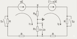
Schematic
Protection Setting Sheet
| No. | Setting Name | Setting Range | Unit | Default Value | Remark |
|---|---|---|---|---|---|
| 1 | One-point Ground Fault Setting | 0.1–100 | kΩ | 10 | Unit: kΩ (kiloohm) |
| 2 | One-point Ground Fault Time Delay | 0–100.00 | s | 5 | Adjustable on-site as required |
| 3 | One-point Ground Fault Mode | 0–2 | — | 2 | 0=Disabled, 1=Trip, 2=Alarm |
| 4 | Two-point Ground Fault Setting | 0.050–0.999 | % | 30% | 0.3, position deviation between one-point and two-point grounding |
| 5 | Two-point Ground Fault Time Delay | 0–100 | s | 2 | |
| 6 | Ground Protection Starting Voltage | 10–500 | V | 50 | Default: 50V; set according to actual excitation voltage |
Dimensions and Cutout Sizes


FAQ
Q:What are the two working principles of the Rotor Earth Fault Protection Relay for generator rotor grounding protection?
A:The principles of generator rotor grounding can be divided into two types: the ping-pong type and the injection type. These two methods must not be used interchangeably.
Q:How is relay protection for generator rotors typically used?
A:Generator rotor ground protection generally serves two functions: single-point ground protection and two-point ground protection. When a single-point ground occurs in the generator rotor, the protection device issues an alarm; when a two-point ground occurs, the protection device trips immediately.
Q:Under what conditions does generator rotor grounding occur?
A:Generator rotor grounding occurs when the rotor winding insulation becomes damaged due to aging, mechanical wear, moisture, overheating or foreign debris, connecting live conductors to the grounded metal rotor shaft.
Additional information
| Rated Voltage | 3.0kV, 3.6kV, 7.2kV, 12kV, 12.7kV, 24kV, 25.2kV, 36kV, 40.5kV, 72.5kV, 126kV, 252kV, 363kV, 550kV, 800kV |
|---|
2 reviews for Ping-Pong Type Rotor Earth Fault Protection Relay 64R
Related products


High Quality
Stable performance, reliable design, ensuring safe operation for power system protection and grid stability.
Fast Delivery
Timely delivery to support your urgent orders and project schedules efficiently and professionally at any time.
Best Warranty
Professional Warranty: Reliable after-sales support for stable relay protection and long-term customer satisfaction.
xiao zhang –
Rotor earth fault relay (ANSI 64R) monitors generator rotor winding insulation damage. High measuring precision, adjustable sensitivity and standard communication, widely used for turbo & hydro generators.
Jack –
Clear LED indicators provide quick status checks at a glance.