

-
Leon Zhang sales consultant
-
Email: zxl635973785@gmail.com
-
Phone/WhatsApp: +86 13655813266
How to Select a Protection Relay for a Power System
Introduction
Effective protection relay selection relies on a comprehensive analysis of on-site system parameters, protected equipment characteristics, CT/PT performance, fault conditions, protection coordination rules, and post-operation communication requirements. Ignoring any of these factors can lead to unplanned downtime, equipment burnout, improper fault isolation, or even entire grid instability. For EPC projects, industrial power systems, and utility substations, mastering standard protective relay selection workflows is critical to ensuring long-term system safety and operational reliability.
This article systematically summarizes practical relay selection criteria for industrial and utility power systems, combining standard industry specifications and real project experience to deliver a fully actionable selection guide for engineering practitioners.
What Is Protection Relay Selection?
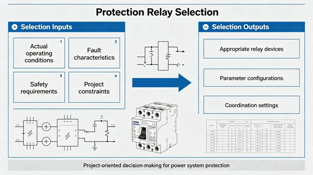
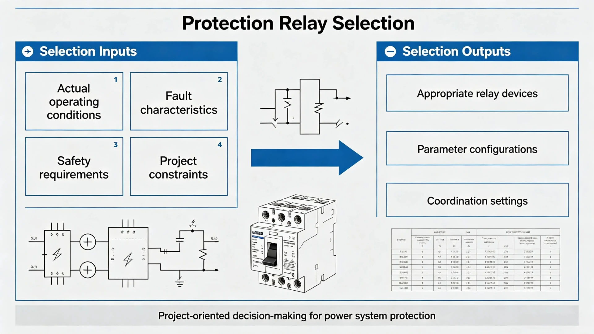
Protection relay selection is the targeted engineering process of matching appropriate protective relay devices and parameter configurations according to the actual operating conditions, fault characteristics, and safety requirements of a specific power system. Unlike general knowledge of relay types or working principles, this process focuses entirely on project-oriented decision-making rather than theoretical introduction.
What Does Protection Relay Selection Involve?
A complete protection relay selection workflow covers all core engineering parameters and application scenarios, including:
- Type and operating characteristics of protected power equipment
- System rated voltage, operating frequency, and auxiliary power supply mode
- Normal continuous load current, peak current, and temporary overload margin
- Maximum and minimum short-circuit fault current of the system
- Matching CT/PT ratio, accuracy class, and anti-saturation performance
- Power system grounding mode and fault type distribution
- Required protection functions and ANSI code configurations
- Primary and backup protection coordination strategies
- Substation communication protocols and automation integration requirements
- On-site environmental conditions and installation specifications
Why Proper Relay Selection Matters
Reasonable protective relay configuration directly determines the safety, stability, and economy of power system operation, with core engineering values reflected in six dimensions:
- Accurate fault detection: Reliably identifies short-circuit, overload, and grounding faults to avoid missed trips
- Selective tripping: Isolates faulty equipment only without affecting the normal operation of healthy circuits
- Dual-layer protection guarantee: Matches primary and backup protection to form a redundant safety barrier
- Equipment damage reduction: Cuts off fault currents quickly to minimize damage to transformers, motors, and lines
- System stability maintenance: Prevents fault diffusion and large-scale grid outages
- Lower operation costs: Effectively avoids nuisance tripping and reduces later maintenance and troubleshooting difficulty
Key Factors to Consider in Protection Relay Selection
This section outlines the core relay selection criteria adopted by mainstream EPC contractors and power utilities, covering all hard parameters that must be confirmed in actual projects.
Identify the Equipment Being Protected
Different power equipment has distinct operating characteristics and fault types, which fundamentally determine the required relay protection functions. There is no universal relay model applicable to all scenarios. The following table summarizes standard protection configurations for typical power equipment:
| Protected Equipment | Common Standard Protection Functions |
|---|---|
| Transformer | Differential protection, overcurrent protection, earth fault protection, overtemperature protection, overload protection |
| Motor | Overload protection, short-circuit protection, phase loss protection, earth fault protection, negative sequence protection |
| Generator | Differential protection, reverse power protection, loss of excitation protection, stator earth fault protection, over/undervoltage protection |
| Distribution Feeder | Instantaneous/time overcurrent protection, earth fault protection, directional overcurrent protection |
| Transmission Line | Distance protection, line differential protection, overcurrent backup protection |
| Busbar | Bus differential protection, breaker failure protection, overcurrent backup protection |
| Capacitor Bank | Overvoltage, undervoltage, overcurrent, unbalance protection |
Verify System Voltage and Frequency Parameters
System voltage and frequency are basic boundary conditions for relay selection, but engineers must distinguish between system main circuit voltage and relay auxiliary supply voltage—two independent parameters that cannot be confused.
Key verification indicators include:
- System rated voltage: Low voltage (0.4kV), medium voltage (6kV/10kV/33kV), high voltage (110kV+)
- System frequency: Fixed 50Hz or 60Hz according to project regional standards
- Relay auxiliary power: AC 220V/110V or DC 220V/110V, matching on-site power supply conditions
Medium and high-voltage systems require relays with stronger electromagnetic interference resistance and wider operating voltage ranges, while low-voltage distribution scenarios prioritize cost-effectiveness and compact installation.
Confirm Normal and Peak Load Current
Selecting a relay only according to the equipment rated current is a typical engineering mistake. Actual power systems have dynamic current fluctuations, which directly determine the relay pickup current setting and thermal withstand capacity.
Current parameters that must be counted:
- Continuous steady-state load current
- Maximum operating current under full-load conditions
- Transient inrush current (motor starting, transformer energization)
- Allowable temporary overload current and duration
- Future load expansion margin of the system
Reasonable pickup current settings must avoid misoperation caused by transient peak currents while ensuring sensitive action when real overload or fault occurs.
Calculate Available Short-Circuit Current
Short-circuit current is the core parameter determining relay fault detection range, CT matching, and protection sensitivity. Different fault types produce completely different fault current magnitudes, which directly affect relay selection and parameter tuning.
Engineers need to obtain and verify:
- Maximum three-phase short-circuit current (used to verify relay and CT withstand capacity)
- Minimum single-phase earth fault current (used to verify protection sensitivity)
- Phase-to-phase short-circuit current parameters
Excessively low protection sensitivity caused by ignoring minimum fault current will lead to un-tripped minor faults, while failure to consider maximum short-circuit current will cause CT saturation and relay malfunction under severe faults.
Match Relay with CT and PT Characteristics
CT/PT is the signal source of protective relays, and mismatched transformer parameters are the main cause of inaccurate sampling and protection failure. This is a key technical difficulty in on-site protective relay selection.
CT Ratio Matching
Common CT ratios for engineering applications include 100/5A, 200/5A, 400/5A, 600/5A, and 600/1A. The relay’s built-in sampling range must cover the CT secondary output current. If the CT ratio is too large, low-current faults cannot be accurately identified; if the ratio is too small, the relay will exceed the measuring range during peak loads.
CT Accuracy and Anti-Saturation Performance
Protection-level CTs (P class) must be used for relay signal sampling, not metering-level CTs. Key indicators include CT accuracy class, rated burden, and saturation resistance. In high short-circuit current systems, CT saturation will distort secondary current waveforms, leading to relay refusal or misoperation. Numerical relays with anti-saturation sampling algorithms are recommended for high-voltage systems.
PT/VT Application Requirements
Relays with voltage-dependent functions need to be matched with PT/VT signal input, including overvoltage, undervoltage, frequency monitoring, directional protection, distance protection, and synchronization check functions. The PT ratio and accuracy class must match the system voltage level to ensure accurate electrical parameter sampling.
Choose the Right Protection Functions (ANSI Code Based)
Functional selection should start with system fault characteristics rather than blind stacking functions. The following are the most commonly used core protection functions in industrial and utility projects, with clear applicable scenarios.
Overcurrent Protection (50/51)
The most basic and widely used protection function, suitable for feeders, distribution transformers, and motor circuits.
- ANSI 50: Instantaneous overcurrent protection, quickly cuts off severe short-circuit faults
- ANSI 51: Time-delay overcurrent protection, acts on overload and general short-circuit faults, with time curve coordination capability
Earth Fault Protection (50N/51N, 50G/51G)
Applicable to all grounded power systems. Selection depends on the system grounding mode (solidly grounded, resistance grounded, ungrounded).
Residual current sampling or zero-sequence CT sampling is adopted for low-current earth faults. Sensitive earth fault protection must be configured for resistance-grounded systems to avoid missing minor grounding faults.
Differential Protection (87)
High-precision main protection for core equipment, applicable to transformers, generators, large motors, busbars, and important transmission lines.
Differential protection has extremely high requirements for CT matching, polarity calibration, and wiring consistency. It can accurately identify internal equipment faults and avoid external fault interference, serving as the first-level main protection for key equipment.
Distance Protection (21)
Specialized protection for medium and high-voltage transmission and sub-transmission lines. It judges fault locations based on line impedance changes, with stable protection ranges and strong adaptability to line load changes.
Directional Protection (67/67N)
Mandatory for ring network power supply, parallel feeders, and distributed generation access systems. It distinguishes fault current directions to prevent cross-tripping of adjacent circuits and ensure selective fault isolation.
Auxiliary Protection Functions
Selectively configured according to project requirements: 27(undervoltage), 59(overvoltage), 46(negative sequence), 49(thermal overload), 81(frequency anomaly), 32(reverse power), 25(synchronism check).
Protection Coordination and Selectivity Requirements
A single qualified relay cannot guarantee system safety; overall protection coordination of the entire power grid is the core goal of standardized protection relay selection.
Relay Time-Current Curve Coordination
Coordinate pickup current, time multiplier setting (TMS), and instantaneous action threshold of upper and lower relays to ensure layered fault isolation. A reasonable coordination margin must be reserved to avoid simultaneous tripping of multiple switches.
Primary and Backup Protection Matching
Key equipment must configure dual protection: primary protection acts quickly for faults, and backup protection takes over to cut off faults when primary protection fails. Relay selection must meet the functional redundancy requirements of primary and backup systems.
Nuisance Tripping Prevention
Relay setting parameters must avoid misoperation caused by motor starting inrush, transformer energization transient current, temporary system overload, and normal switching operations. Reasonable time-delay and threshold settings are required to balance sensitivity and stability.
Electromechanical vs Static vs Numerical Protection Relays
For project procurement and design, relay type selection focuses on scenario adaptability rather than technical generation advantages. The comparative analysis of three mainstream relay types is as follows:
| Relay Type | Advantages | Limitations | Typical Application Scenarios |
|---|---|---|---|
| Electromechanical Relay | Simple structure, strong robustness, low failure rate, no complex configuration | Single function, fixed parameters, no communication capability, slow action speed | Old legacy power stations, simple low-voltage distribution systems |
| Static Relay | Fast response, compact size, stable performance | Single fixed function, poor expandability, unable to realize remote monitoring | Traditional medium-voltage simple protection scenarios |
| Numerical Relay | Multi-functional integration, flexible parameter setting, complete communication interface, remote monitoring, fault recording, strong scalability | Relatively complex configuration, higher technical requirements for debugging | Modern substations, EPC projects, new energy power generation, intelligent power distribution systems |
At present, numerical protection relays have become the mainstream choice for new projects and renovation projects due to their comprehensive performance and intelligent integration capabilities.
Communication and Automation Integration Requirements
Intelligent substation and automated power distribution systems have strict requirements for relay communication capabilities, which are easily overlooked in traditional selection processes.
Communication Protocol Matching
Select protocols according to substation automation standards: IEC 61850 (intelligent substation mainstream), Modbus RTU/TCP (industrial distribution mainstream), DNP3, IEC 60870-5-103/104 (utility grid standard).
Upper System Compatibility
Relays need to support data interaction with SCADA, PLC, HMI, and remote monitoring platforms to realize remote signal acquisition, fault alarm, and remote parameter adjustment.
Digital I/O Configuration
Confirm the number of binary inputs, trip outputs, alarm outputs, and breaker status acquisition interfaces to meet on-site control and signal feedback requirements.
Environmental and Installation Selection Criteria
Relay long-term operating stability depends on matching on-site environmental conditions:
- Installation location: Indoor control room, outdoor switchgear cabinet, substation field (different waterproof, dustproof, and anti-interference grades required)
- Environmental parameters: Operating temperature range, humidity resistance, vibration resistance, electromagnetic interference resistance
- Installation method: Panel mounting, rack mounting, DIN rail mounting (matching cabinet body design standards)
Practical Protection Relay Selection Checklist (Featured Snippet Ready)
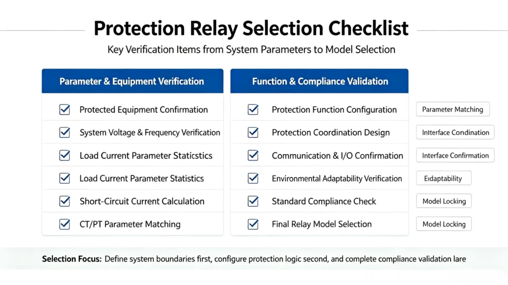
Confirm all items one by one before finalizing the relay model to avoid omissions:
- Confirm the type and protection demand of protected equipment
- Verify system rated voltage, frequency, and auxiliary power supply parameters
- Count steady-state load current, peak current, and overload margin
- Obtain maximum/minimum short-circuit current data of the system
- Match CT ratio, protection grade, and anti-saturation performance
- Confirm whether PT/VT voltage signal input is required
- Determine the required combination of protection functions and ANSI codes
- Check system grounding mode and earth fault protection configuration
- Complete upper and lower relay protection coordination verification
- Confirm directional/differential protection special requirements
- Match on-site communication protocol and automation integration requirements
- Verify digital input and output quantity configuration
- Check on-site environmental adaptability and installation mode
- Confirm compliance with industry standard specifications and certification requirements
- Reserve margin for future system expansion and upgrading
Engineering Case: Relay Selection for 33kV Distribution Feeder
Project Basic Parameters
- System voltage: 33kV, 50Hz
- System grounding: Solidly grounded system
- CT configuration: 400/5A protection class CT
- Maximum continuous load current: 280A
- Maximum short-circuit current: 12.5kA
- Communication requirement: Support Modbus TCP and IEC 61850
Step-by-Step Selection Process
- Confirm protection functions: Match feeder conventional protection, configure 50/51 overcurrent protection + 50N/51N earth fault protection
- Verify CT matching: 400/5A CT secondary current range matches relay sampling interval, with anti-saturation adaptation for 12.5kA short-circuit current
- Set current parameters: Pickup current set according to 280A maximum load current + 20% expansion margin, avoid inrush current misoperation
- Check short-circuit withstand: Relay meets 12.5kA short-time current withstand requirement
- Confirm communication: Select numerical relay with dual protocols to meet substation intelligent monitoring
- Complete coordination verification: Match time-current curve with upper substation relay to ensure selective tripping
Case Conclusion: 33kV feeder protection relay selection cannot rely only on voltage and current ratings. Function matching, CT adaptability, fault withstand capability, protection coordination, and communication expansion must be fully verified to ensure long-term reliable operation.
Common Mistakes in Protection Relay Selection
Summarize typical errors in engineering selection to help teams avoid project risks:
- Selecting only by rated parameters: Ignoring load fluctuation and fault characteristics leads to poor protection adaptability
- Neglecting CT saturation: Causes waveform distortion and protection failure under high short-circuit current
- Over-configuring protection functions: Excess functions increase configuration complexity and hidden misoperation risks
- Missing protection coordination design: Leads to non-selective tripping of the whole network
- Ignoring communication requirements: Results in inability to access automation systems and poor intelligent operation and maintenance
- Universal relay for all scenarios: Using the same relay model for different equipment leads to insufficient targeted protection
- No reserved expansion margin: Failing to adapt to future load growth and system renovation
Standard vs Multifunction Protection Relay: How to Choose
Project procurement needs to balance cost and performance, avoiding blind pursuit of full-function models:
| Application Requirement | Standard Single-Function Relay | Multifunction Numerical Relay |
|---|---|---|
| Simple low-voltage feeder protection | ✅ Recommended | Optional |
| Basic overcurrent/earth fault protection | ✅ Recommended | ✅ Recommended |
| Multiple composite protection functions | ❌ Not applicable | ✅ Mandatory |
| SCADA remote integration | Limited support | Full support |
| Fault recording and data analysis | No support | Full support |
| Complex substation core equipment protection | ❌ Not applicable | ✅ Mandatory |
Core principle: Select the most matching relay according to actual protection requirements and system architecture. Excess functions will increase procurement and debugging costs, while insufficient functions will bring hidden safety hazards.
Industry Standards and Certification Basis for Relay Selection
All selected protection relays must comply with international general electrical standards to ensure engineering qualification and operational safety. The core reference standards are as follows:
- IEC 60255: Universal standard for measuring relays and protection equipment, specifying relay performance, test methods, and environmental adaptability
- IEC 61850: International standard for substation communication and automation, governing relay digital communication and system integration
- IEEE/ANSI C37 series: American standard for power system protection, defining ANSI protection function codes and coordination rules
- IEC 61000 series: EMC electromagnetic compatibility standard, ensuring relay stable operation in complex electromagnetic environments
Final Standard Protection Relay Selection Flowchart
Conclusion
Qualified protection relay selection is never a simple model matching based on voltage and current parameters. It is a systematic engineering decision that integrates equipment characteristics, system fault parameters, transformer matching, protection logic, grid coordination, intelligent communication, and on-site environment. Standardized protective relay selection and strict implementation of relay selection criteria are the key to ensuring safe, stable, and economical operation of industrial and utility power systems.
Whether you are undertaking EPC substation projects, industrial power distribution renovation, or new energy power system construction, our professional team can provide customized protection relay selection schemes, parameter debugging suggestions, and system coordination optimization services according to your on-site system voltage, CT ratio, load parameters, and protection requirements.
Technical Reference & Data Sources
- IEC 60255-1:2021 Measuring relays and protection equipment – Part 1: General requirements
- IEC 61850-7-4:2018 Communication networks and systems for power utility automation
- IEEE C37.112-2018 Standard for Inverse Time Characteristic Equations for Overcurrent Relays
- IEC 61000-6-5:2019 Electromagnetic compatibility (EMC) – Power system immunity requirements
- International Council on Large Electric Systems (CIGRE) Working Group B5.04: Power System Protection Coordination Guidelines
FAQ
1. What factors should be considered in protection relay selection?
The main factors include the protected equipment, system voltage and frequency, load current, short-circuit current, CT and PT characteristics, required protection functions, protection coordination, communication requirements, auxiliary power supply, installation environment, and applicable standards.
2. How do I choose the right protection relay for a power system?
Start by identifying the equipment that needs protection, such as a transformer, feeder, motor, generator, or transmission line. Then determine the required protection functions, system and fault parameters, CT/PT configuration, coordination requirements, and communication interfaces. The relay should meet all of these requirements rather than being selected based only on voltage or current ratings.
3. What are the main relay selection criteria?
The main relay selection criteria include:
- System voltage and frequency
- Rated and maximum load current
- Maximum and minimum fault current
- CT ratio and accuracy class
- PT/VT requirements
- Required protection functions
- Protection coordination
- Communication protocols
- Digital inputs and outputs
- Auxiliary power supply
- Environmental conditions
- Applicable standards
4. Does CT ratio affect protection relay selection?
Yes. The CT ratio determines the current input available to the relay and directly affects protection sensitivity and setting ranges. CT accuracy, burden, and saturation characteristics should also be checked, particularly for differential and high-current protection applications.
5. Should I choose a multifunction numerical protection relay?
A multifunction numerical relay can be a good choice when a system requires several protection functions, event recording, measurement, communication, or SCADA integration. For a simple application with only basic overcurrent or earth-fault protection, a simpler relay may be more practical and cost-effective.
6. How does protection coordination affect relay selection?
Protection coordination determines how relays operate during faults and which circuit breaker should trip first. The selected relay must provide suitable pickup, time-delay, and instantaneous settings so that primary and backup protection can coordinate correctly.
7. What protection relay is suitable for a 33 kV feeder?
A 33 kV feeder commonly requires overcurrent and earth-fault protection, such as ANSI 50/51 and 50N/51N. Depending on the network configuration, directional overcurrent protection, communication, fault recording, and other functions may also be required. The final relay selection should be based on the feeder’s CT ratio, fault level, grounding system, coordination study, and control requirements.
8. What is the difference between protection relay selection and protective relay selection?
Protection relay selection and protective relay selection generally refer to the same engineering process: choosing a relay that matches the electrical system, protected equipment, fault conditions, protection functions, and coordination requirements. “Protection relay selection” is commonly used in technical discussions, while “protective relay selection” is a closely related search term.
9. What happens if the wrong protection relay is selected?
An unsuitable relay may have insufficient sensitivity, incorrect operating characteristics, poor coordination, incompatible CT/PT inputs, or inadequate communication capabilities. This can result in nuisance tripping, delayed fault clearance, failure to detect faults, or unnecessary equipment outages.
10. Can the same protection relay be used for transformers, motors, and feeders?
Not necessarily. Different electrical equipment has different protection requirements. For example, transformers may require differential and inrush-related protection, motors need protection against overload and phase-related faults, while feeders often rely on overcurrent and earth-fault protection. Relay selection should therefore be based on the specific application rather than using one relay type for every circuit.



About Author

Hello, I'm Leno Zhang. I have 15 years of experience in the power relay protection industry with extensive pre-sales and after-sales project experience. Our company specializes in various complete sets of relay protection and automation equipment. I can assist customers in solving all practical on-site project challenges and provide optimal integrated solutions.
Tell Us Your Requirement
High Quality
Stable performance, reliable design, ensuring safe operation for power system protection and grid stability.
Fast Delivery
Timely delivery to support your urgent orders and project schedules efficiently and professionally at any time.
Best Warranty
Professional Warranty: Reliable after-sales support for stable relay protection and long-term customer satisfaction.