

-
Leon Zhang sales consultant
-
Email: zxl635973785@gmail.com
-
Phone/WhatsApp: +86 13655813266

Motor Protection Relay Setting Calculation Guide
Motor Protection Relay Setting Calculation: What Gets Set
Motor protection relay setting calculation is the list of pickup values and time delays entered into a motor protection relay for ANSI 49 thermal, 51 overcurrent, 50 instantaneous, 51LR locked rotor, 46 negative sequence, 51N earth fault, 48 start supervision and 87M differential. Every value comes from the nameplate, the CT ratio and the upstream curve.
Start with the nameplate.
Everything else scales from it.
At a glance, the worked example further down this page (350 A motor, 12 s DOL start, 600/5 CT) lands on these eight values:
- 49 thermal: 350 A, which is 1.0 × FLA; Class 20 relay curve
- 51 time-overcurrent: 403 A, which is 1.15 × FLA; TMS set to trip in about 2 s at 6 × FLA
- 50 instantaneous: 2450 A, which is 7 × FLA; that clears the 6.5 × FLA starting current
- 51LR locked rotor: 1.05 × LRA pickup; 14.4 s delay, under the 20 s hot stall limit
- 48 start supervision: 16.8 s, which is 1.4 × the 12 s starting time
- 46 negative sequence: 15 % FLA pickup; trips at 12 % unbalance after 1 s
- 51N earth fault: 10 % FLA on a resistance-grounded system; 1 s delay
- 87M differential: 25 % Irated with 30 % and 70 % slopes; blocked during start
A starter overload relay sees current but has no reference for the starting curve. A circuit breaker sees magnitude only, so it clears a stalled motor after the winding has already heated. Neither device can tell a 12-second start from a sustained overload.
Device numbers follow ANSI/IEEE C37.2-2022. Table values for conductor and overload sizing follow NEC Article 430. The relay hardware itself falls under the IEC 60255 series, IEC 60255-1:2022 in particular.
This motor relay setting guide walks the same ground in commissioning order. Motor data first. Then the FLA. Each setting function gets its own section after that, then the CT conversion, the coordination check against the upstream breaker and the mistakes that show up most often on site.

Why Proper Motor Protection Relay Settings Matter
An incorrectly configured three-phase motor protection relay can be just as dangerous as having no protection at all. The hardware these settings run on is listed in the motor protection relays category. A motor protection relay setting calculation that ignores the starting curve is what produces that result.
Settings Too High
Possible consequences:
- Motor winding damage
- Bearing overheating
- Fire hazards
- Expensive motor replacement
Settings Too Low
Possible consequences:
- Frequent nuisance trips
- Production interruptions
- Reduced equipment availability
The goal is to protect the motor without affecting normal operation.
Motor Data Required for Relay Setting Calculation
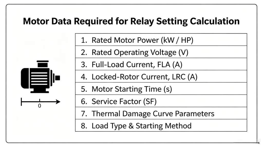
Accurate relay settings depend on complete and correct motor data. Missing or incorrect parameters can cause nuisance tripping or protection failure. The table below lists the key motor data required for setting calculation. Every later motor protection relay setting calculation inherits that error, so confirm the data before you calculate.
Essential Motor Data
| Parameter | Symbol | Description | Purpose |
|---|---|---|---|
| Rated Power | Pn | Nameplate power rating (kW/hp) | Determines protection requirements and relay selection |
| Rated Voltage | Un | Nameplate voltage (e.g., 380V, 6kV, 10kV) | Voltage protection settings and CT/PT ratio verification |
| Full Load Current | FLA/In | Nameplate full-load current (A) | Base value for all overcurrent, overload, and unbalance settings |
| Locked Rotor Current | LRA/Ist | Starting current, typically 6-8 × FLA | Sets instantaneous overcurrent pickup; must exceed starting current |
| Locked Rotor Time (Hot) | LRHOT | Maximum allowable stall time when hot (seconds) | Determines overload trip curve limit |
| Locked Rotor Time (Cold) | LRCOLD | Maximum allowable stall time when cold (seconds) | Determines cold start capability; affects start supervision setting |
| Starting Time | tst | Time to reach rated speed (seconds) | Sets start supervision and locked rotor time delay |
| Thermal Capacity / Damage Curve | I²t | Motor thermal withstand curve (current vs. time) | Defines damage limit; relay curve must fall below this curve |
| Service Factor | SF | Typically 1.0 or 1.15 | Adjusts overload pickup setting |
| Motor Design Type | NEMA/IEC | NEMA A/B/C/D or IEC classification | Determines starting characteristics; affects coordination |
| Insulation Class | F/H | F, H, etc. | Defines maximum allowable temperature rise |
| Starts Per Hour | starts/h | Maximum allowable cold/hot starts per hour | Sets starts-per-hour protection (66); prevents thermal stress |
| Cooling Time Constant | τ | Thermal cooling time constant | Required for thermal model accuracy during cooling |
| CT Ratio | n/5A | Primary/secondary ratio (e.g., 100/5A) | Converts primary current to relay input |
| PT Ratio (if applicable) | n/100V | e.g., 10kV/100V | Converts primary voltage to relay input |
Additional Data for Motors with RTD Sensors
| Parameter | Description | Purpose |
|---|---|---|
| RTD Type | PT100, PT1000, or Ni120 | Determines temperature input configuration |
| RTD Locations | Windings (3) + Bearings (2-3) | Identifies monitoring points and alarm/trip thresholds |
| Alarm Temperature | Typically 120-140°C for Class F | Early warning |
| Trip Temperature | Typically 140-160°C for Class F | Immediate shutdown |
Verification Checklist
- □ Nameplate data is complete and matches the actual motor
- □ CT ratio matches relay input range
- □ Starting method is confirmed (DOL/Star-Delta/Soft-Starter/VFD)
- □ Motor damage curve has been obtained
- □ System grounding method is known
- □ Upstream protection device characteristics are available
Motor Full Load Current Calculation
Motor full-load current (FLC or FLA) is the foundation for all protection relay settings, conductor sizing, and switchgear selection. The motor protection relay setting calculation starts here, because almost every pickup below is a multiple of FLA. Accurate calculation ensures the motor starts reliably while protection devices trip correctly during faults.
Full-Load Current vs. Full-Load Amps
A critical distinction in motor calculations:
| Term | Source | Use For |
|---|---|---|
| FLC (Full-Load Current) | NEC/IEC standard tables | Branch-circuit conductor sizing, short-circuit protection, disconnecting switch rating |
| FLA (Full-Load Amps) | Motor nameplate rating | Overload protection settings, relay calibration |
Never use nameplate current for conductor sizing; always use table values per NEC 430.6(A)
Three-Phase Motor FLC Formula
When standard tables are unavailable, calculate FLC using:
I = P / (√3 × V × η × PF)
| Parameter | Symbol | Description |
|---|---|---|
| I | Full-load current | Calculated value (Amperes) |
| P | Rated power | Motor output power (Watts; multiply kW by 1000) |
| V | Line voltage | System voltage (Volts) |
| η | Efficiency | Motor efficiency (typically 0.90–0.96) |
| PF | Power factor | Typically 0.85 for induction motors |
Single-Phase Motor FLC Formula
I = P / (V × η × PF)
Approximate FLC from Standards
For quick reference, NEC Table 430.250 provides standard three-phase motor full-load currents:
| HP | 208V | 230V | 460V | 575V |
|---|---|---|---|---|
| 5 | 16.7 | 15.2 | 7.6 | 6.1 |
| 10 | 30.8 | 28 | 14 | 11 |
| 25 | 74.8 | 68 | 34 | 27 |
| 50 | 143 | 130 | 65 | 52 |
| 100 | 273 | 248 | 124 | 99 |
Application of FLC in Protection Sizing
Conductor Sizing (NEC 430.22)
Minimum conductor ampacity = FLC × 125%
Overload Protection (NEC 430.32)
- Motors with service factor ≥1.15: ≤125% of nameplate FLA
- All other motors: ≤115% of nameplate FLA
Instantaneous Overcurrent Pickup
Typically 6–8 × FLC (must exceed motor starting current)
Motor Protection Relay Setting Calculation Methods
Motor protection relay setting calculation is the process of determining the appropriate pickup values and time delays for each protection function to ensure the relay operates correctly during faults while allowing normal motor starting and running. The goal is to position the relay operating curve between the motor starting curve and the motor damage curve, providing maximum protection without nuisance tripping. This section outlines the calculation methods for key motor protection functions.
Motor Overload Relay Setting
Overload protection (ANSI 49) protects the motor against prolonged operation above rated current. The core motor protection setting formulas for 49 are pickup and trip class, both anchored on FLA. It uses a thermal model with an inverse-time characteristic, so the higher the current, the faster the trip.
Key Parameters Required:
- Motor FLA (full-load current)
- Service factor (typically 1.0 or 1.15)
- Trip class (Class 10/20/30 based on starting time)
- Motor thermal damage curve
- CT ratio
Calculation Method:
Pickup Setting (Overload Current Threshold):
The 49 thermal setting calculation is Pickup = FLA × 1.0 for motors with SF ≥ 1.15, and FLA × 0.90–0.95 for SF = 1.0.
- For motors with SF ≥ 1.15: Pickup = FLA × 1.0
- For motors with SF = 1.0: Pickup = FLA × 0.90–0.95
Trip Class Selection:
- Class 10: For motors starting within 10 seconds (typical for most LV motors)
- Class 20: For motors starting within 10–20 seconds (high-inertia loads)
- Class 30: For motors starting within 20–30 seconds (very high-inertia loads)
Thermal Model Settings:
- Hot/cold stall time ratio: Typically 0.7–0.8 (motor can withstand ~70-80% of cold stall time when hot)
- Cooling time constant: Set per motor manufacturer data (typical 15–30 minutes for LV motors, 30–60 minutes for MV motors)
- RTD bias: Enable RTD inputs for winding temperature correction (recommended for MV motors)
Example: 200kW, 380V Motor
- FLA = 350A, SF = 1.15, Starting time = 12 seconds
- Overload pickup = 350A × 1.0 = 350A (primary)
- Trip class = Class 20 (starting time 12s falls in 10–20s range)
- RTD alarm = 130°C, RTD trip = 145°C (Class F insulation)
Overcurrent Protection Setting
Overcurrent protection(ANSI 50/51) provides backup protection for phase-to-phase and phase-to-ground faults. The time overcurrent element (51) uses inverse-time characteristics, while the instantaneous element (50) provides high-speed clearing for severe faults.
Key Parameters Required:
- Motor FLA
- Motor starting current (6–8 × FLA)
- Motor starting time
- Upstream protection coordination
- CT ratio
Calculation Method:
Overcurrent Pickup (51):
- Set at 115–125% of FLA
- Must be below motor stator damage curve and above maximum continuous load
- Formula: Pickup = FLA × 1.15 (minimum)
Time Dial Setting:
- Select IEC or IEEE inverse curve based on system requirements
- Coordinate with upstream devices: ensure 0.2–0.3 second margin between operation curves
- Time dial should allow successful motor start but trip before motor damage occurs
Instantaneous Pickup (50):
- Typically set at 6–8 × FLA
- Must exceed maximum motor starting current to avoid nuisance tripping during start
- Formula: Pickup = LRA × 1.1–1.2 (must be below cable damage curve)
Example: 6kV, 1000kW Motor
- FLA = 120A, Starting current = 750A (6.25 × FLA)
- Time OC pickup = 120 × 1.15 = 138A
- Instantaneous pickup = 750 × 1.2 = 900A (7.5 × FLA)
- IEC standard inverse curve, time dial selected to trip at 2s for 6× FLA fault current
Locked Rotor Protection Setting
Locked rotor protection (ANSI 51LR) detects when the motor fails to start or becomes mechanically jammed during operation, drawing locked rotor current (6–8 × FLA) for an extended period.
Key Parameters Required:
- Locked rotor current (LRA)
- Locked rotor time (hot and cold)
- Motor starting time
- CT ratio
Calculation Method:
Pickup Setting:
- Set at 100–110% of LRA (or 6–8 × FLA)
- Must be above maximum normal starting current to avoid tripping during start
Time Delay Setting:
- Must exceed normal starting time
- Set at 1.1–1.2 × maximum starting time
- Must be less than locked rotor withstand time (from motor damage curve)
Start Supervision (ANSI 48):
- Set at 1.2–1.5 × normal starting time
- If motor still drawing locked rotor current after this time, relay trips
Example:
- LRA = 6.5 × FLA = 780A, Starting time = 15 seconds
- Locked rotor pickup = 780A × 1.05 = 819A (6.8 × FLA)
- Locked rotor time delay = 15 × 1.2 = 18 seconds
- Start supervision = 15 × 1.4 = 21 seconds
Stall Protection Setting
Stall protection monitors the motor current during starting. It protects against prolonged acceleration due to low voltage, high inertia, or mechanical overload.
Key Parameters Required:
- Starting current profile
- Normal starting time
- CT ratio
Calculation Method:
Start Monitoring:
- Monitors current drawn during starting sequence
- If current does not drop below 1.0–1.1 × FLA within the allowable starting time, relay trips
Setting Values:
- Trip after normal starting time × 1.2–1.5
- The stall current threshold is set at 100–120% of FLA; if current remains above this after normal start time, a stall condition is detected
Functional Principle:
- During a stalled condition, current remains high (approaching locked rotor level) for an extended period
- The timer starts when the motor is energized and continues until current falls below the stall threshold (typically 100–120% of FLA)
- If current remains above threshold when timer expires, relay trips
Phase Loss Protection Setting
Phase loss (or single-phasing) occurs when one phase of the three-phase supply is lost. This condition causes the motor to draw excessive current in the remaining phases, leading to rapid overheating and potential motor burnout.
Key Parameters Required:
- Motor FLA
- CT ratio
Calculation Method:
Negative Sequence Unbalance Setting (ANSI 46):
- Set at 10–20% of FLA
- Alarm threshold: Typically 8% unbalance
- Trip threshold: Typically 12% unbalance
Current Unbalance Calculation:
- Calculate unbalance using the phase currents:
- Average current = (IA + IB + IC) / 3
- Maximum deviation = Max |IA – Iavg|, |IB – Iavg|, |IC – Iavg|
- Unbalance (%) = (Maximum deviation / Average current) × 100
Typical Settings:
- Unbalance alarm: 10% with 2–3 second delay
- Unbalance trip: 15% with 0.5–1 second delay
- Phase loss trip: <20% of FLA with immediate trip
Motor Earth Fault Relay Setting
Earth fault protection (ANSI 50N/51N) detects ground faults that may not produce significant phase overcurrent, particularly in resistance-grounded systems where earth fault currents are limited.
Key Parameters Required:
- System grounding method
- Earth fault current level (from system study)
- CT ratio (including zero-sequence CT)
- CT cable shield grounding arrangement
Calculation Method:
Earth Fault Setting:
- For resistance-grounded systems: Set at 5–15% of FLA
- For solidly grounded systems: Set at 20–40% of FLA
- For ungrounded systems: Use sensitive earth fault (50N) at 2–5% of FLA
Zero-Sequence CT Selection:
- Must be sized for the available earth fault current
- CT ratio must provide sufficient secondary current at minimum fault level for reliable operation
Time Delay Setting:
- Alarm: 0.5–1 second delay
- Trip: 1–2 second delay (coordinate with upstream earth fault protection)
**Important: Cable shield grounding must be carefully implemented to avoid misoperation from shield currents. The shield should be grounded only at one point to prevent circulating currents through the CT.
Underload Protection Setting
Underload protection (ANSI 37) detects loss of load conditions such as pump dry running, broken fan belt, or loss of prime. It prevents equipment damage and energy waste.
Key Parameters Required:
- Motor normal running current at minimum load
- Motor FLA
- CT ratio
Calculation Method:
Underload Pickup Setting:
- Set at 40–70% of FLA (depending on application)
- For pumps: 50–70% of FLA (dry running protection)
- For fans: 40–60% of FLA (belt breakage detection)
- For compressors: 50–65% of FLA (loss of compression)
Time Delay Setting:
- Typically 3–10 seconds delay to avoid nuisance tripping during transient load reductions
- Must allow for normal load variations
Example:
- Pump motor FLA = 100A, Normal running current at minimum load = 55A
- Underload pickup = 55A × 0.9 = 50A (50% of FLA)
- Time delay = 5 seconds
Negative Sequence Protection Setting
Negative sequence protection (ANSI 46) protects the motor against unbalanced supply conditions that generate negative-sequence currents and cause excessive rotor heating.
Key Parameters Required:
- Motor FLA
- Motor K factor (derating factor for unbalance) from motor manufacturer
- CT ratio
Calculation Method:
Negative Sequence Pickup Setting:
- Set at 10–20% of FLA
- Formula: Pickup = FLA × 0.1–0.2
Time Delay Setting:
- Alarm: 3–5 seconds delay
- Trip: 1–2 seconds delay
K Factor Application:
The K factor (typically 2–8) determines the degree of additional heating caused by unbalance. A higher K factor means the motor is more sensitive to unbalance.
Example:
- FLA = 100A, K factor = 4
- Negative sequence pickup = 100 × 0.15 = 15A (15% of FLA)
- Trip delay = 1 second
Motor Differential Protection Setting
Differential protection (ANSI 87M)provides fast and sensitive protection for stator winding internal faults (phase-to-phase and turn-to-turn faults) in large motors (>2000kW). Cross-check the motor side against the 87M protection settings page before the setting sheet is released.
Key Parameters Required:
- Motor rated current
- CT ratio (line and neutral CTs)
- CT characteristics (5P20 or PX class recommended)
- Motor starting time
- Motor design data
Calculation Method:
Differential Pickup Setting:
- Set at 20–40% of rated current
- Must be above maximum unbalance current under normal conditions
- Formula: Pickup = Irated × 0.2–0.4
Slope Settings:
- Slope 1: 20–30% (for low through-fault currents)
- Slope 2: 60–80% (for high through-fault currents, external faults)
Start Blocking:
- Block differential during starting for 10–15 seconds (or until current drops below 2 × FLA)
- Prevents maloperation due to CT saturation during start
Example: 1.4MW, 11kV Motor
- Rated current = 90A
- Differential pickup = 90 × 0.2 = 18A (20% of rated)
- Slope 1 = 30%, Slope 2 = 70%
- Start blocking: 12 seconds
Three-Stage Current Protection Setting
Three-stage current protection provides progressive protection against different levels of fault current, using three independent overcurrent stages.
Stage 1: Instantaneous Overcurrent (ANSI 50)
| Parameter | Setting Rule | Purpose |
|---|---|---|
| Pickup | 6–8 × FLA | High-speed clearing of severe faults near the motor |
| Time Delay | 0–0.1 seconds | Instantaneous trip for high-magnitude faults |
Stage 2: Definite-Time Overcurrent
| Parameter | Setting Rule | Purpose |
|---|---|---|
| Pickup | 3–5 × FLA | Clearing moderate overcurrent conditions |
| Time Delay | 0.2–0.5 seconds | Fixed time delay for selectivity with other devices |
Stage 3: Inverse-Time Overcurrent (ANSI 51)
| Parameter | Setting Rule | Purpose |
|---|---|---|
| Pickup | 1.15–1.25 × FLA | Backup protection for faults with lower current levels |
| Time Dial | Coordinated with upstream/downstream curves | Inverse-time characteristic provides coordinated protection |
Coordination between Stages:
- Stage 1 should clear high-magnitude faults with no intentional delay
- Stage 2 should operate for moderate fault levels with a short time delay
- Stage 3 should provide backup protection for all other overcurrent conditions
Example:
- FLA = 200A, Starting current = 1200A
- Stage 1 pickup = 200 × 7 = 1400A (7 × FLA), delay 0s
- Stage 2 pickup = 200 × 4 = 800A (4 × FLA), delay 0.3s
- Stage 3 pickup = 200 × 1.2 = 240A (1.2 × FLA), IEC inverse curve, TMS = 0.1
Important Notes for All Settings:
- Always verify settings against motor manufacturer damage curves
- Coordinate with upstream protection devices (0.2–0.3 second margin)
- Test settings using fault simulation software
- On-site commissioning verification is essential
- Settings should be stored and documented per serial number for traceability
Motor Protection Relay Setting Calculation Example
This section provides a practical calculation example for a medium-voltage motor protection relay. Every number in it comes from the motor protection relay setting calculation steps above.
Motor Data
| Parameter | Value |
|---|---|
| Rated Power | 1.4 MW |
| Rated Voltage | 11 kV |
| Full Load Current (FLA) | 90 A |
| Locked Rotor Current (LRA) | 585 A (6.5 × FLA) |
| Starting Time | 12 seconds |
| LR Time (Hot / Cold) | 20s / 30s |
| Service Factor | 1.15 |
| CT Ratio | 150/5 A (30:1) |
Setting Summary
| Protection | ANSI | Primary Pickup | Secondary Pickup | Time Delay |
|---|---|---|---|---|
| Overload | 49 | 90 A (Class 20) | 3.00 A | Inverse-time |
| Overcurrent (51) | 51 | 103.5 A (1.15×FLA) | 3.45 A | IEC Inv, TMS=0.1 |
| Instantaneous OC | 50 | 630 A (7×FLA) | 21.0 A | 0 s |
| Locked Rotor | 51LR | 614 A (1.05×LRA) | 20.5 A | 14.4 s |
| Start Supervision | 48 | 90 A | 3.00 A | 16.8 s |
| Negative Sequence | 46 | 13.5 A (15% FLA) | 0.45 A | 1 s |
| Earth Fault | 51N | 9.0 A (10% FLA) | 0.30 A | 1.0 s |
| Differential | 87M | 22.5 A (25% Irated) | 0.75 A | Start blocked |
| Undervoltage | 27 | 8.8 kV (80%%) | n/a (voltage) | 2 s |
| Overvoltage | 59 | 12.65 kV (115%%) | n/a (voltage) | 1 s |
Key Setting Principles Applied
- Overload (49): Pickup = FLA × 1.0 (SF ≥1.15); Class 20 selected based on 12s starting time
- Overcurrent (51): Pickup = FLA × 1.15; TMS coordinated to operate at ~2s for 6×FLA fault current
- Instantaneous (50): Pickup = 7×FLA, must exceed starting current (6.5×FLA)
- Locked Rotor (51LR): Pickup = 1.05×LRA; delay = 12s × 1.2 = 14.4s (< hot stall 20s)
- Start Supervision (48): Delay = 12s × 1.4 = 16.8s
- Negative Sequence (46): Pickup = 15% FLA; trip at 12% unbalance with 1s delay
- Earth Fault (51N): Pickup = 10% FLA (resistance-grounded system); 1s delay
- Differential (87M): Pickup = 25% Irated; Slope1=30%, Slope2=70%; blocked during 12s start
- Under/Over Voltage: 80% / 115% of rated voltage with 2s / 1s delay
Coordination Verification
| Check | Result |
|---|---|
| Overcurrent vs. Starting | 2s trip at 6×FLA; motor reaches speed in 12s → no nuisance trip |
| Instantaneous vs. Starting | Pickup 630A > starting 585A → allows normal start |
| Locked Rotor vs. Damage | Trip at 14.4s < hot stall 20s → protects motor |
| Differential Start Blocking | Blocked for 12s → prevents CT saturation maloperation |
CT Ratio and Relay Setting Conversion
Current transformers (CTs) convert primary currents to manageable secondary levels for relays and instruments. Correct CT ratio selection and proper conversion between primary and secondary values are essential for accurate protection settings. Get the CT wrong and the whole motor protection relay setting calculation is off by that factor.
Why CT Ratio Matters
CT ratio determines the relationship between primary current (motor current) and secondary current (relay input). If the CT ratio is incorrect, all protection settings will be wrong, leading to nuisance tripping or failure to protect the motor.
Standard CT Ratios
| CT Ratio | Primary Current | Secondary Current | Application |
|---|---|---|---|
| 100/5 | 100A | 5A | Small LV motors |
| 200/5 | 200A | 5A | Standard LV motors |
| 400/5 | 400A | 5A | Large LV motors |
| 100/1 | 100A | 1A | MV motors (long cable runs) |
| 600/5 | 600A | 5A | MV motors |
| 1200/5 | 1200A | 5A | Large MV motors |
Standard secondary ratings: 5A (most common) or 1A (for long distances).
CT Ratio Selection
Step 1: Determine Primary Current Range
- CT primary rating should be approximately 125–150% of motor FLA
- Must handle motor starting current (6–8 × FLA) without saturation
CT Ratio Selection Rule:
CT Primary ≥ FLA × 1.25 (minimum)
CT Primary ≥ FLA × 1.5 (recommended)
Example:
- Motor FLA = 350A
- CT Primary = 350 × 1.5 = 525A
- Select standard CT: 600/5A
CT Saturation Considerations
CTs must remain accurate during high fault currents to ensure correct relay operation.
Saturation Check:
- CT must not saturate at maximum fault current
- CT knee-point voltage must exceed maximum secondary voltage at fault
- For differential protection, 5P20 or PX class CTs are recommended
Primary-to-Secondary Conversion
Formula:
Secondary Current = Primary Current × (CT Secondary / CT Primary)
Example:
- CT Ratio = 600/5A (ratio = 120:1)
- Motor FLA = 350A (primary)
- Secondary FLA = 350 × (5/600) = 350 / 120 = 2.92A
General Conversion:
| To Convert | Calculation |
|---|---|
| Primary → Secondary | Isecondary = Iprimary × (CTsec / CTpri) |
| Secondary → Primary | Iprimary = Isecondary × (CTpri / CTsec) |
Relay Setting Conversion
All relay settings must be converted from primary values to secondary values based on the CT ratio.
Conversion Steps:
- Calculate the relay setting in primary amps based on motor data
- Divide by CT ratio to obtain secondary amps for relay programming
Example:
| Setting | Primary Value | CT Ratio | Secondary Value |
|---|---|---|---|
| Overload Pickup | 90A | 600/5 | 90/120 = 0.75A |
| Overcurrent Pickup | 103.5A | 600/5 | 103.5/120 = 0.86A |
| Instantaneous Pickup | 630A | 600/5 | 630/120 = 5.25A |
Note: Most digital relays allow programming in both primary and secondary values, but always verify which unit is used.
Quick Reference Conversion Table
| CT Ratio | CT Factor | Conversion (A→A) |
|---|---|---|
| 100/5 | 20 | ÷20 |
| 150/5 | 30 | ÷30 |
| 200/5 | 40 | ÷40 |
| 300/5 | 60 | ÷60 |
| 400/5 | 80 | ÷80 |
| 500/5 | 100 | ÷100 |
| 600/5 | 120 | ÷120 |
| 800/5 | 160 | ÷160 |
| 1000/5 | 200 | ÷200 |
| 1200/5 | 240 | ÷240 |
Zero-Sequence CT for Earth Fault Protection
For sensitive earth fault protection, a zero-sequence CT (core-balance CT) is used.
Selection Rule:
- Primary rating: Typically 50–100% of motor FLA
- Must detect minimum earth fault current reliably (typically 5–15% of FLA)
Example:
- Motor FLA = 350A
- Select zero-sequence CT: 200/5A
- Earth fault pickup = 10% FLA = 35A (primary) → 35/40 = 0.88A (secondary)
Common Mistakes to Avoid
| Mistake | Consequence |
|---|---|
| Using wrong CT ratio | All settings off by factor |
| Forgetting to convert | Relay set incorrectly |
| CT saturation at faults | Relay fails to operate |
| Mixing 5A and 1A CTs | Incorrect scaling |
| Wrong CT polarity (differential) | Nuisance tripping |
Motor Protection Relay Setting Coordination
Protection coordination ensures that when a fault occurs, the correct protection device operates to isolate only the faulted section while keeping the rest of the system online. Without proper coordination, a fault on a motor circuit could trip the upstream feeder breaker, shutting down an entire production line unnecessarily. This section outlines the principles and methods for coordinating motor protection relay settings with upstream and downstream devices. The motor protection relay setting calculation is still unfinished until those curves are checked together.
What Is Protection Coordination?
Protection coordination is the systematic grading of protection device operating times and currents to achieve selective tripping. When a fault occurs at any point in the system, the protection device closest to the fault should operate first. Only if that device fails should upstream devices operate as backup.
The Selective Tripping Principle:
- Fault on motor circuit → Motor relay trips first
- Motor relay fails → Feeder relay trips as backup
- Feeder relay fails → Incoming relay trips as backup
Coordination Partners
Motor protection relays coordinate with:
| Device Type | Location | Role |
|---|---|---|
| Upstream protection | Feeder breaker, substation relay | Backup protection if motor relay fails |
| Downstream protection | Local switchgear, branch circuits | Must coordinate to avoid nuisance tripping |
| Other motor relays | Same bus, same feeder | Must coordinate to isolate only the faulted motor |
Note: Coordination is not limited to protection devices; it also applies to:
- Switchgear ratings: Must withstand fault current until protection operates
- Cable ratings: Must survive fault current for the clearing time
- CT ratings: Must remain accurate for the coordination time
Coordination Goals
| Goal | Description |
|---|---|
| Selectivity | The nearest device trips first; upstream devices provide backup only |
| Speed | Faults are cleared as quickly as possible to minimize damage |
| Security | Protection operates correctly for all fault types and locations |
| Stability | The system remains stable during and after fault clearing |
Coordination with Upstream Protection
The motor protection relay must coordinate with the upstream feeder relay to ensure selectivity.
Key Rule:
- The upstream relay must have a longer operating time than the motor relay for all fault current levels
- A minimum time margin of 0.2–0.3 seconds should be maintained
Coordination Method:
- Plot the motor relay operating curve
- Plot the upstream relay operating curve
- Ensure the upstream curve is to the right of the motor curve for all current values
- Check that the time margin is at least 0.2 seconds at maximum fault current
Example:
- Motor relay trip time at 6×FLA = 1.0 second
- Upstream relay trip time at same current must be ≥1.3 seconds (1.0 + 0.3)
Coordination with Motor Starting Curve
Protection settings must coordinate with the motor starting current and duration to avoid nuisance tripping.
Starting Current Profile:
- Inrush current: 6–8 × FLA at start, decaying to FLA as motor reaches speed
- Duration: 5–30 seconds depending on motor size and load inertia
Key Rules:
- Overcurrent relay curve must be above the motor starting curve
- Instantaneous pickup must be higher than the maximum starting current
- Locked rotor time delay must exceed the normal starting time
Coordination Check:
- Plot the motor starting current curve (current vs. time)
- Plot the protection relay operating curve
- Ensure the relay curve is above and to the right of the starting curve
- Verify sufficient margin to prevent nuisance tripping during start
Coordination with Motor Damage Curve
The protection relay must operate before the motor is damaged by overheating. The motor damage curve (thermal withstand curve) defines the safe operating limit.
Key Rules:
- The relay curve must be below and to the left of the motor damage curve
- The relay must trip before the motor reaches its thermal limit
Coordination Check:
- Obtain the motor damage curve from the motor manufacturer
- Plot the protection relay operating curve
- Ensure the relay curve is below the damage curve for all overload conditions
Coordination Time Margins
| Margin | Recommended Value | Purpose |
|---|---|---|
| Upstream-downstream | 0.2–0.3 seconds | Ensures selectivity between devices |
| Relay vs. starting curve | >0.1 seconds | Prevents nuisance tripping |
| Relay vs. damage curve | 10–20% margin | Ensures motor protection before damage |
Coordination Example: Motor Feeder
Consider a motor supplied from a feeder breaker with upstream protection.
| Device | Pickup (A) | Trip Time at 6×FLA |
|---|---|---|
| Motor Relay (51) | 103.5A (1.15×FLA) | 1.0 second |
| Feeder Relay (51) | 120A | 1.4 seconds |
| Incoming Relay (51) | 150A | 2.0 seconds |
Result:
- Motor fault → Motor relay trips at 1.0s (selective)
- Motor relay fails → Feeder relay trips at 1.4s (backup)
- Feeder relay fails → Incoming relay trips at 2.0s (backup)
Coordination Problems and Solutions
| Problem | Cause | Solution |
|---|---|---|
| Motor trips on start | Relay curve below start curve | Increase time dial or pickup |
| Motor fails to trip on fault | Relay curve above damage curve | Decrease time dial or pickup |
| Upstream trips for motor fault | Time margin too small | Increase upstream time delay |
| Relay trips on CT saturation | CT undersized | Use higher class CT |
Common Motor Protection Relay Setting Mistakes
Incorrect relay settings can leave motors unprotected or cause frequent tripping. Below are common mistakes and how to prevent them. Most of them trace back to one step of the motor protection relay setting calculation done too early or not at all.
Common Setting Mistakes Summary
| Mistake | Consequence | Prevention |
|---|---|---|
| Wrong CT ratio | All settings scaled incorrectly | Verify CT nameplate matches relay configuration |
| Overload setting too high | Motor runs overloaded without tripping; thermal damage accumulates | Set 100% FLA (SF≥1.15) or 90-95% FLA (SF=1.0) |
| Overload setting too low | Nuisance tripping during normal operation | Set 100% FLA (SF≥1.15) |
| Altitude not considered | Motor overheats at high altitude | Derate 3% per 1000m above 1000m altitude |
| Instantaneous pickup too low | Trips on every start | Set 6-8 × FLA, above maximum starting current |
| Locked rotor delay too short | Trips during normal start | Set 1.1-1.2 × normal starting time |
| Overcurrent time dial too fast | Trips on start or upstream coordination failure | Set to allow start with 0.2-0.3s coordination margin |
| No coordination with upstream | Motor fault trips upstream breaker; entire line shuts down | Verify 0.2-0.3s margin with upstream curve |
| Motor damage curve ignored | Motor damaged before relay operates | Relay curve must fall below damage curve |
| CT saturation at fault | Relay fails to operate | Use CTs with sufficient knee-point voltage; 5P20/PX class for differential |
| Using instantaneous instead of definite-time | Upstream coordination failure | Use 51 for backup coordination; 50 only for high-magnitude faults |
| No testing before commissioning | Undiscovered errors cause failure during real faults | Use secondary injection testing before energization |
Six Records Before Handover
- Use a standardized setting calculation sheet
- Obtain complete motor data before calculation
- Plot coordination curves for verification
- Test settings before energization
- Store settings by serial number
- Review settings after commissioning
Motor Protection Relay Commissioning Checklist
Commissioning verifies relay settings and wiring before the motor enters service. The following checklist covers pre-energization checks, secondary injection testing, and live commissioning tests. It also confirms the values produced by the motor protection relay setting calculation.
Pre-Energization Checks
| No. | Check Item | Status | Notes |
|---|---|---|---|
| 1 | Relay firmware version matches specification | ☐ | Record version |
| 2 | Configuration file loaded correctly | ☐ | Verify parameters |
| 3 | CT ratio matches actual CT nameplate | ☐ | Check primary/secondary |
| 4 | PT ratio matches actual PT (if applicable) | ☐ | Verify scaling |
| 5 | All protection settings entered per calculation sheet | ☐ | Cross-check each |
| 6 | Communication parameters configured | ☐ | IP, baud rate, etc. |
| 7 | Date and time set correctly | ☐ | Sync with plant time |
| 8 | CT/PT polarity correct | ☐ | Verify S1/S2, phase sequence |
| 9 | All terminal connections tightened to torque spec | ☐ | Use torque wrench |
| 10 | Ground connection secure | ☐ | Measure resistance |
| 11 | Trip and alarm circuits functional | ☐ | Manual test contacts |
Secondary Injection Testing (Motor De-Energized)
| No. | Test Item | Acceptance Criteria | Status |
|---|---|---|---|
| 12 | Overload (49) | Trip at calculated pickup (±5%) | ☐ |
| 13 | Overcurrent (51) | Trip time matches curve (±5%) | ☐ |
| 14 | Instantaneous (50) | Trip at pickup (±3%) | ☐ |
| 15 | Locked Rotor (51LR) | Trip time within ±5% | ☐ |
| 16 | Start Supervision (48) | Trip after set delay | ☐ |
| 17 | Negative Sequence (46) | Trip at set unbalance (±5%) | ☐ |
| 18 | Earth Fault (50N/51N) | Trip at pickup (±5%) | ☐ |
| 19 | Differential (87M) | Trip at pickup; verify slopes | ☐ |
| 20 | Under/Over Voltage (27/59) | Trip at set voltage (±5%) | ☐ |
| 21 | Undercurrent (37) | Trip at pickup (±5%) | ☐ |
| 22 | Starts/Hour (66) | Block after count exceeded | ☐ |
Communication Verification
| No. | Check Item | Acceptance Criteria | Status |
|---|---|---|---|
| 23 | Modbus/IEC 61850 communication | Relay responds to read requests | ☐ |
| 24 | SCADA/DCS integration | All points read correctly | ☐ |
| 25 | Remote control commands | Relay responds to remote trip/close | ☐ |
Live Commissioning Tests (Motor Energized)
| No. | Test Item | Acceptance Criteria | Status |
|---|---|---|---|
| 26 | Motor starts without tripping | No trip during start | ☐ |
| 27 | Phase currents balanced | Unbalance < 5% | ☐ |
| 28 | Voltage measurement correct | Within ±2% of actual | ☐ |
| 29 | Relay display matches measured values | Correct readings | ☐ |
| 30 | Alarm contacts operate at thresholds | Triggers correctly | ☐ |
| 31 | Communication data matches relay display | SCADA values match | ☐ |
| 32 | Load test (50%, 75%, 100%) | No nuisance trips; accurate readings | ☐ |
Documentation and Sign-Off
| No. | Document | Status |
|---|---|---|
| 33 | Commissioning report completed | ☐ |
| 34 | Setting record saved (digital + hard copy) | ☐ |
| 35 | Calibration certificate included | ☐ |
| 36 | As-built wiring diagram updated | ☐ |
| Role | Name | Signature | Date |
|---|---|---|---|
| Commissioning Engineer | |||
| Site Manager / Client |
Post-Commissioning Recommendations
- Save digital backup of all settings
- Perform annual secondary injection testing
- Review settings after major motor maintenance
- Keep commissioning report for future reference
FAQ
What is the best overload setting for a motor?
If you work from a thermal relay instead, that figure comes from the motor protection relay setting calculation for 49 as well. Most industrial motors use 105–120% of full load current.
How do I calculate locked rotor protection?
Typically 6–8 times motor full load current with a suitable time delay.
Can I use the same settings for VFD motors?
No. VFD-driven motors often require different overload and stall protection settings due to harmonic content and controlled startup characteristics.
How often should relay settings be reviewed?
Settings should be checked after commissioning, maintenance work, process modifications, or motor replacement. Re-run the motor protection relay setting calculation after any of those events before you reload the file.
How to test motor protection relay?
Perform secondary injection test to simulate fault currents and voltages, verify all protection functions, trip logic and operating time. Shops that do not own the rig can book a test session through the relay protection training and testing service.
Where can I find motor protection relays?
You can contact us, we are a professional motor protection relay wholesaler in China.
Which fault condition thermal overload relay protects ac induction motor
It mainly protects against thermal overload and sustained overcurrent caused by locked rotor, phase loss, long-time heavy load.
What is the wholesale price of motor protection relays?
You can contact us, we are a professional motor protection relay wholesaler and motor protection relay supplier in China, offering favorable wholesale prices for motor protection relays.
What key parameters should be checked when selecting a motor protection relay?
A: Verify motor rated current, rated voltage, start-up time, service category, and motor type (induction motor, synchronous motor). Core protection functions include 50/51 overcurrent, 49 thermal overload, 46 negative-sequence unbalance, 50N earth-fault, stall protection and locked-rotor protection. Confirm CT secondary rating, communication protocol and cabinet installation space. The motor protection relay selection step comes first: the relay you shortlist fixes the input range you then calculate for.
Conclusion
Motor protection relay setting calculation does not stop at the arithmetic. It ends at the secondary injection test, where the values written on the sheet are forced to operate against real current.
Three checks gate the whole exercise.
- Start with the nameplate.
- Confirm the CT ratio twice.
- Plot the relay curve under both the starting curve and the damage curve.
Miss any one of them and you inherit one of two failure modes: nuisance trips on every start, or nothing at all during a fault.
Record the values.
Verify them with current.
Energise the motor last.
Sources
| Source | What it covers | Type | Edition |
|---|---|---|---|
| ANSI/IEEE C37.2-2022 | Device function numbers used throughout this guide: 48, 49, 46, 50, 51, 51LR, 51N and 87M | IEEE standard | 2022 |
| IEC 60255-1:2022 | Common requirements for measuring relays and protection equipment, including accuracy and trip time limits | IEC standard | Edition 2.0, 2022 |
| NFPA 70, Article 430 | Motor full-load current tables, conductor sizing (430.22) and overload trip limits (430.32) | NFPA code | Article 430 |
| IEC 61850 series | Relay-to-SCADA communication and setting file exchange during commissioning | IEC standard | IEC 61850 |
| Relayprotect setting worksheet | Worked 350 A example, CT ratio conversion table and commissioning checklist used on this page | Manufacturer application note | Rev. 1, 2026 |
Related Reading
Relay protection training and testing service
How to select a motor protection relay
Motor protection relays supplied by Relayprotect
Locked rotor protection relay settings



About Author

Hello, I'm Leno Zhang. I have 15 years of experience in the power relay protection industry with extensive pre-sales and after-sales project experience. Our company specializes in various complete sets of relay protection and automation equipment. I can assist customers in solving all practical on-site project challenges and provide optimal integrated solutions.
Tell Us Your Requirement
High Quality
Stable performance, reliable design, ensuring safe operation for power system protection and grid stability.
Fast Delivery
Timely delivery to support your urgent orders and project schedules efficiently and professionally at any time.
Best Warranty
Professional Warranty: Reliable after-sales support for stable relay protection and long-term customer satisfaction.