
-
Leon Zhang Sales Manager
-
Email: sale@relayprotect.com
-
Phone/WhatsApp: +86 13655813266
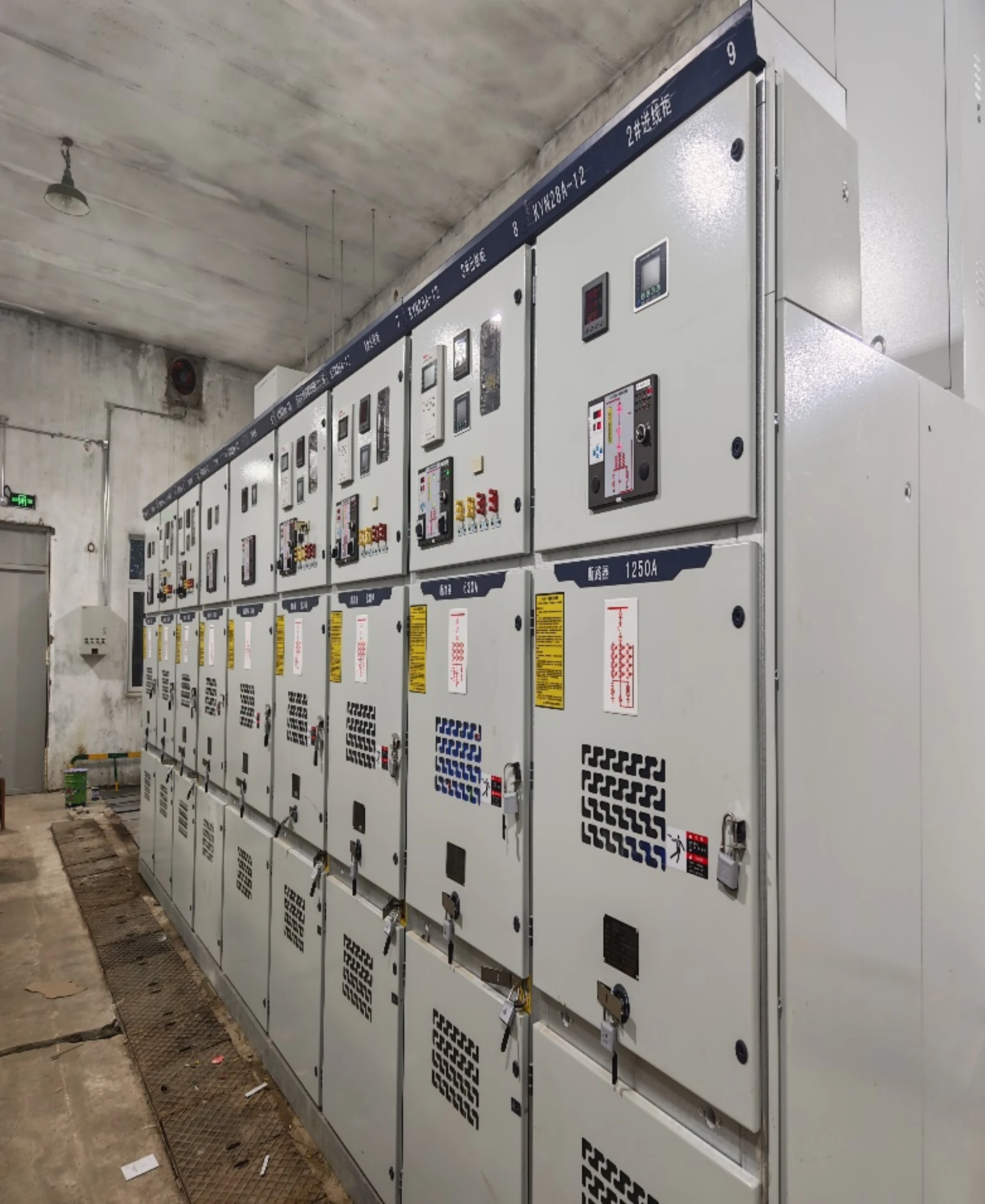
Protection of Switchgear: Components, Challenges and Selection
What does switchgear protection include?
Switchgear protection is the set of relays, current transformers, trip circuits and interlocks built into a medium-voltage switchgear assembly. It detects a fault, decides whether the fault sits inside its own zone, and opens the breaker before arc energy damages the cubicle. Four steps repeat on every cubicle: measure, compare, trip, and prove the trip path. The cubicle is a mechanical enclosure rated under IEC 62271-200:2021, and protection is the layer that decides when to open it; a breaker that cannot interrupt its rated short-circuit current, or a trip circuit already open when the fault arrives, turns a survivable cable fault into a destroyed compartment. The components fall into four layers – enclosure, primary switching device, instrument transformers and secondary circuit – and a weak link in any layer leaves the other three useless. Functions come from ANSI/IEEE C37.2-2022, relays from IEC 60255-1:2022 and CTs from IEC 61869-2:2012. Setting review and quotation within 12 hours, MOQ 1, 7-15 working days.
Switchgear protection is the set of relays, current transformers, trip circuits and interlocks built into a medium-voltage switchgear assembly. It detects a fault, decides whether the fault sits inside its own zone, and opens the circuit breaker before arc energy damages the cubicle. Four steps repeat on every cubicle: measure, compare, trip, prove the trip path.
Four steps. One cubicle.
The cubicle is a mechanical enclosure rated under IEC 62271-200:2021+AMD1:2024. Protection is the layer that decides when to open it. A breaker that cannot interrupt its rated short-circuit current, or a trip circuit that is already open when the fault arrives, turns a survivable cable fault into a destroyed compartment. That is why the board and its protection are specified together rather than bought from two vendors.
Function numbers come from ANSI/IEEE C37.2-2022. Relay performance and type testing follow IEC 60255-1:2022. The current transformers feeding the relay are specified under IEC 61869-2:2012, the breaker under IEC 62271-100:2021+AMD1:2024, and electromagnetic immunity for equipment installed in substations under IEC 61000-6-5:2015.

Switchgear Protection: At a Glance
Object first. Functions second.
Each cubicle type carries a different function set. Start from the object, then add the functions.
- Feeder cubicle: 50/51 phase overcurrent and 50N/51N earth fault, set above maximum load and below minimum fault.
- Transformer cubicle: 87T differential as the main function, 50/51 as backup, 49 for thermal stress.
- Motor cubicle: 49 thermal overload, 46 negative-sequence unbalance, 48 stalled rotor.
- Busbar and incomer: 87B busbar differential, plus 50BF breaker failure to trip the next breaker up.
- Capacitor bank: 50/51 with 27/59 voltage supervision and unbalance detection across the bank.
- RMU and compact substation: 50/51 and 50N, often self-powered from the CT with no auxiliary supply.
- Arc fault inside the cubicle: light or pressure sensing supervised by 50/51 current, so a lamp or a camera flash cannot trip the board.
- Overhead feeder duty: 79 auto-reclose, blocked for cable sections and for faults inside the cubicle.
The related pages go deeper on each one: the RMU protection relay, arc fault protection, and the smart switchgear controller that carries many of these functions in one device.
Selecting a relay for a live project?
Send the system voltage, CT ratio and tripping scheme. Our engineers confirm the model and reply within 12 hours.
Switchgear Protection Components: Cabinet, Breaker, CT, Relay, Trip Path
Every cubicle carries all four.
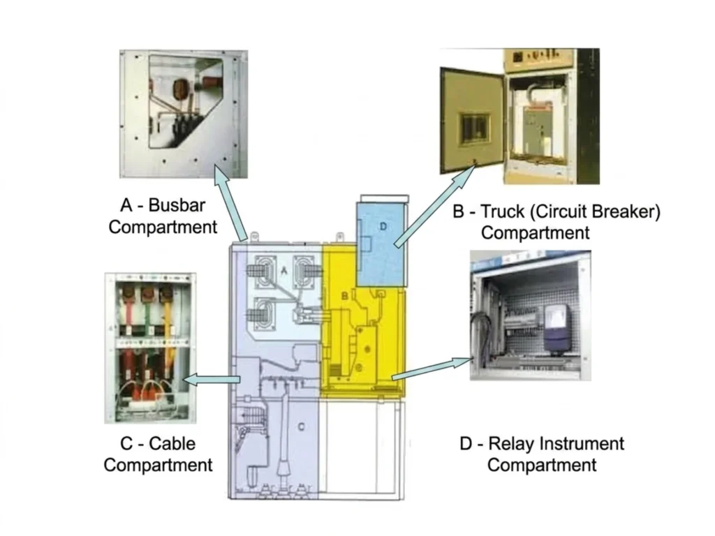
These components fall into four layers: the enclosure and its compartments, the primary switching device, the instrument transformers that measure, and the secondary circuit that decides and trips. A weak link in any layer leaves the other three useless, which is why the four are specified as one chain. The table lists each part and what it actually does.
| Component | Brief Introduction |
|---|---|
| Switchgear Cabinet | Equipped with four separate compartments. It provides isolation, restrains arc faults, dust and moisture, and complies with IP standards. |
| Circuit Breaker | Mainly VCB and SF6 types. Performs regular switching and cuts fault current to prevent fault spread. |
| Current Transformers (CTs) | Convert high current for relays and decide the performance of multiple protection functions. |
| Voltage Transformers (VT/PT) | Conduct voltage sampling and metering, supporting voltage and frequency protection. |
| Protection Relays | Core control unit. Monitors parameters, identifies faults and triggers tripping, with full protection functions for medium voltage switchgear. |
| Multifunction Power Meter | Tracks electrical data and power quality to assist energy management and equipment maintenance. |
| Switchgear Operation Display | Presents real-time data, supports local control and fault alarm for convenient operation. |
| Trip Circuit and Supervision | Carries the trip command from relay to coil. Supervision alarms on an open circuit before the fault arrives, not during it. |
| Interlocks | Mechanical and electrical locks that stop racking, earthing or closing out of sequence. Type tested as part of the assembly under IEC 62271-200:2021+AMD1:2024. |
| Arc Detection Sensors | Light or pressure sensors inside the compartments. They trip only when current supervision confirms a fault. |
Why the Relay Decides What Happens in a Cubicle
One device makes the call.
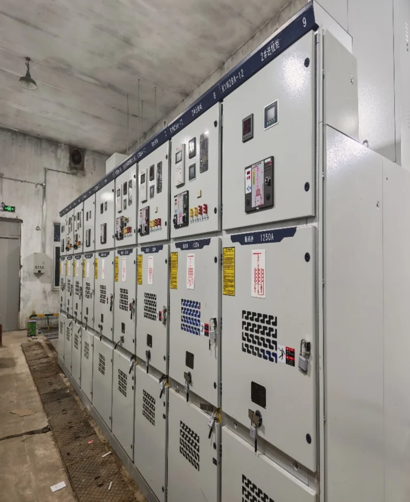
Among all switchgear components, the relay is the part that decides. A correctly configured unit clears the fault within its operating time, while a misconfigured one turns a contained cable fault into an outage that reaches the rest of the board.
Without a dependable relay, minor faults such as short circuits and overloads keep expanding. What follows is transformer burnout, cable breakdown, internal arc faults, and outages that reach well past the failed compartment.
Utilities, EPC contractors and industrial users judge a scheme on five things: dependability, operating time, compliance with IEC standards, network security, and protocol compatibility with the SCADA already in place. Each one can be checked on paper before purchase, and each one is expensive to fix afterwards.
Switchgear Protection Selection: Six Checks Before You Order
Six inputs. One decision.
An MV switchgear protection relay is chosen on six inputs, not on brand. Get the six right and the relay model follows from them; get one wrong and no amount of parameter tuning will rescue the scheme.
| Check | What to compare | What proves it |
|---|---|---|
| System voltage and earthing | Rated voltage, neutral earthing arrangement, maximum fault level at the busbar | Short-circuit study and single line diagram |
| Protected object | Feeder, transformer, motor, capacitor bank or busbar | Load list and object nameplate ratings |
| CT class and ratio | Ratio, accuracy limit factor, burden, knee-point voltage | CT datasheet checked against the relay burden |
| Required functions | Which ANSI numbers the scheme needs and which are optional | Function list from the protection philosophy document |
| Trip and auxiliary supply | Trip coil voltage, auxiliary supply source, trip circuit supervision | Secondary schematic and DC system arrangement |
| Communication and integration | IEC 61850, Modbus TCP/RTU, DNP3, plus the SCADA point list | Protocol conformance statement and agreed point list |
Object first, CT second, functions third. A relay with the right functions on a saturated CT will misoperate, and a relay with the right CT and the wrong functions cannot see the fault at all.
Eight Problems Buyers Hit When Purchasing Switchgear and Protection
Based on years of overseas project service experience, we have summarized the eight most common pain points and confusions of global customers in the procurement, design and operation of electrical switchgear and protection, targeting the core demands of overseas engineering and procurement teams.
Problem 1: selection of switchgear and protection devices
The model is the symptom.
Most customers are confused about matching relay models: Should I use a feeder protection relay or a multifunction protection relay for my switchgear project? Different application scenarios such as feeders, motors, transformers and capacitor banks correspond to completely different protection logic and relay functional configurations. Blind selection will lead to insufficient protection functions or functional redundancy and cost waste.
Our Solution: We provide professional one-on-one model selection services. According to the customer’s single line diagram, load parameters and project scenario, we accurately match feeder protection relays, transformer protection relays, switchgear arc flash protection,motor protection relays and busbar protection relays, and provide the selection guidelines that match each one to its scenario.
Problem 2: Doubts About the Compliance of Chinese Protection Devices
Ask for report numbers.
Many overseas customers worry that relays built in China cannot meet international standards and regional certification requirements, and that the board will fail grid connection and acceptance. It is the first concern raised on European, Southeast Asian, Middle Eastern and African power projects.
What to ask for: type and routine test reports to IEC 60255-1:2022, a protocol conformance statement for IEC 61850-8-1:2011+AMD1:2020, immunity test reports to IEC 61000-6-5:2015, and the CE declaration naming the directive it was issued under. Ask for report numbers rather than certificate logos. A report can be checked with the issuing lab; a logo cannot.
Problem 3: Incompatible Communication Protocols
A converter is a failure point.
A common post-installation problem is that the purchased protection device cannot be docked with the customer’s existing SCADA system due to inconsistent communication protocols, resulting in inability to realize remote monitoring and centralized control, making the intelligent switchgear lose its automated functions.
Our Solution: Our intelligent protection relays and supporting automation devices carry IEC 61850, Modbus TCP, Modbus RTU and DNP3 inside the device rather than through an external converter. That keeps the SCADA point list identical to the relay database, with no mapping table to maintain.
Problem 4: CT Selection Errors Cause Relay Maloperation
A saturated CT hides the fault.
Improper CT configuration is one of the main causes of protection failures inside a cubicle. The usual offenders are an unreasonable CT ratio, an insufficient accuracy class, excessive burden and reverse polarity wiring. Each of them drives the CT into saturation during a real fault, and a saturated CT hides the fault from the relay.
Our Solution: Our professional engineering team provides free CT parameter review services, including verification of CT ratio, burden capacity and accuracy class, and guides on-site wiring to completely avoid system faults caused by mismatched CT and protection relays.
Problem 5: Lack of Secondary Design Capability Leads to Long Engineering Cycles
Drawings set the schedule.
Most overseas customers and EPC teams only have primary design drawings (single line diagram and load list) and lack professional secondary circuit design capabilities. It is impossible to complete schematic design, wiring design and protection logic configuration independently, resulting in delayed project progress and prolonged engineering cycle.
Our Solution: We provide full-process secondary engineering design support. Customers only need to provide basic technical drawings and specifications, and our team can complete all professional work including secondary schematics, wiring diagrams, terminal layout drawings and protection logic design, greatly shortening the project engineering cycle.
Problem 6: Difficult and Unreasonable Relay Parameter Setting
Defaults are not settings.
Most on-site engineers lack professional relay setting experience, and often face confusions such as How should I set overcurrent protection parameters? and How to complete protection curve coordination? Unreasonable setting values will lead to poor protection selectivity, frequent tripping or failure of fault response, affecting system stability.
Our Solution: We provide professional relay setting calculation, protection coordination study and on-site commissioning guidance services. According to the customer’s system fault current, grid capacity and project requirements, we set values that balance sensitivity against selectivity for that network.
Problem 7: Inadequate Overseas After-Sales and Spare Parts Support
Spares are a schedule item.
Overseas project operation faces cross-regional service barriers. Customers are worried about no timely technical support after equipment faults, and the time difference leads to delayed problem solving. In addition, the lack of local spare parts inventory leads to long equipment maintenance and replacement cycles.
Our Solution: We provide 24/7 remote after-sales troubleshooting, online commissioning and technical consultation services to solve cross-timezone service problems. At the same time, we hold global spare parts inventory so a replacement does not wait on a factory slot, which is what actually sets the downtime.
Problem 8: Long Delivery Cycle of European and American Brands
Lead time is a design input.
Imported European and American brand protection relays and supporting equipment usually have a long delivery cycle of 20–40 weeks, which cannot meet the rapid construction cycle requirements of overseas small and medium-sized power projects, and easily lead to project delay and cost increase.
Our Solution: As a professional Chinese manufacturer, we have standardized production lines and sufficient inventory reserves. The conventional delivery cycle is only 2–8 weeks, and we support personalized customized development according to project needs, with more flexible delivery and customized solutions.
How We Help Customers Build Reliable Power System Protection and Switchgear Solutions
Four jobs. One contract.
What follows is the scope a coherent package has to cover: product supply, engineering design, technical commissioning and after-sales service. Putting those four on one contract is what closes the interface gaps between the board builder and the relay supplier.
1. Complete Protection Relay Product Portfolio
We have a full range of independent research and development and production of protection relay products, covering all medium voltage switchgear application scenarios: Feeder Protection Relay, Transformer Protection Relay, Motor Protection Relay and Busbar Protection Relay.
All products are compliant with international standards, with stable performance and high cost performance, meeting the differentiated protection needs of various power projects.
2. Integrated Switchgear Automation Solution
We provide integrated system matching, combining protection relays, multifunction power meters, HMI touch screens, RTU units and communication gateways in one package. A single purchase order covers every device in the cubicle, which removes the compatibility arguments that follow from splitting the order across suppliers.
3. Full-Cycle Professional Engineering Support
From project design to final commissioning, we provide full-process technical support. After customers provide single line diagrams and project technical specifications, our team completes protection scheme design, secondary schematic drawing design, relay parameter configuration and factory pre-testing, so installation and commissioning start from a configuration already tested at the factory.
4. Standard IEC 61850 Smart Substation Solution
Our intelligent protection system fully supports IEC 61850 MMS, GOOSE and Modbus TCP, which is suitable for intelligent upgrading and reconstruction of utility substations, solar power stations, wind farms and large industrial plants. It helps customers build digital, automated and intelligent modern power distribution systems.
Case Study – 110 kV Substation Protection System, Overseas Project
Four inputs in, three documents out.
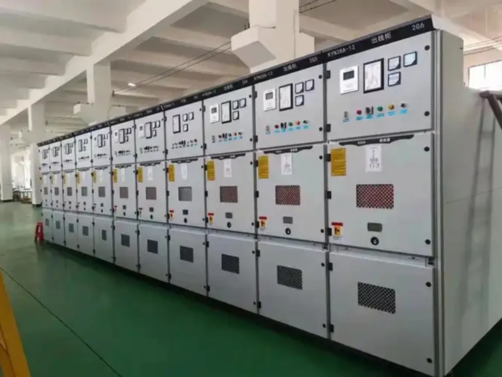
We have delivered medium and high voltage turnkey projects in Uzbekistan, Kazakhstan, Africa, the Middle East and other overseas regions, supplying protection panels together with the switchgear they were built into.
Project Scope of Supply: Complete sets of protection panels, AC/DC power distribution panels, metering panels, central alarm panels, transformer protection panels and line protection panels.
Project Highlights: The customer only provided basic project drawings and technical requirements. Our team independently completed all secondary engineering design, equipment selection, scheme optimization and factory testing.
Compared with the industry average cycle, the project delivery time was shortened by 30%, and all equipment passed local grid acceptance at one time, achieving stable and safe operation after grid connection, and the client accepted the panels without a return factory visit.
Frequently Asked Questions
The nine questions buyers ask.
1. What protection relay is used in switchgear?
Modern medium voltage switchgear is mainly equipped with multifunction relays covering overcurrent, earth fault, voltage, frequency and differential protection. The specific functional configuration is adjusted according to the switchgear application scenario and load type.
2. How many protection relays are needed in a switchgear lineup?
The number of protection relays depends on the actual scale of the project, including the number of feeder loops, the number of supporting transformers, busbar structure and load types. Each independent power loop gets its own dedicated relay, so a fault on one loop does not depend on another loop’s settings.
3. What communication protocols should a modern relay support?
For intelligent substations and remote monitoring, a modern relay has to carry IEC 61850, Modbus TCP, Modbus RTU and DNP3. Ask which of those run natively on the device and which need a gateway, because a gateway adds both a failure point and a configuration file to maintain.
4. Can protection relay settings be customized?
All relay protection parameters can be customized and adjusted professionally. According to the project’s power system capacity, short-circuit fault current, grid operation specifications and customer personalized requirements, we complete targeted setting calculation and protection curve coordination to adapt to different operating environments.
5. What should be noted during the selection of switchgear protection?
Start with system voltage, load current and the earthing arrangement, then check the working environment: ambient temperature, altitude, humidity and whether the room is indoors. Local standards matter too, because some grids require type tests to IEC 62271-200:2021+AMD1:2024 while others accept national equivalents. Write the four inputs down before comparing models.
6. What main components constitute a complete set of switchgear and protection?
A full set includes the cubicle with its compartments, the circuit breaker or switch, current and voltage transformers, the protection relay, the trip circuit with supervision, and the local monitoring or display device. The last two are the ones buyers drop, and an unproven trip path is the one that fails first.
7. What features should medium voltage switchgear protection relays have?
Medium voltage switchgear protection relays should cover 50/51 phase overcurrent, 50N/51N earth fault and 27/59 voltage functions as a minimum, be type tested to IEC 60255-1:2022, and offer either IEC 61850-8-1 or Modbus for integration. Anything beyond those depends on the object: 87T on a transformer, 49 and 46 on a motor, 87B on a busbar.
8. Which scenarios require switchgear arc flash protection?
Arc detection earns its place wherever people work on or near live cubicles: medium and high voltage distribution rooms, substations, and industrial systems with high fault levels. It pays for itself where incident energy at the working distance is high, where the board is ageing, or where the incoming fault level has grown since the board was built. An arc flash protection relay combines light sensing with current supervision, so the trip needs both conditions.
9. What causes most switchgear protection failures in service?
Most in-service failures trace back to five causes: CT saturation, reversed CT polarity, an open trip circuit, a lost auxiliary supply, and settings left at the factory default. None of them are relay defects, and all of them surface during commissioning rather than in the specification. A scheme whose trip path has never been proven will look healthy until the day it is needed.
Conclusion
Prove the trip path.
Modern medium voltage switchgear is no longer a simple distribution board. It measures, protects, communicates and reports, and all four jobs depend on the same secondary circuit being right on the day of the fault.
To start, send four things: the single line diagram, the CT and VT ratings, the short-circuit level at each busbar, and the protocol list your SCADA expects. You get back a function list with ANSI numbers, a draft setting sheet, and an I/O schedule for the cubicle.
Technical References
Editions change. Check them.
Every claim above maps to a document you can ask a supplier to produce. The edition matters, because acceptance authorities check it, and several of these standards changed their internal arc and interlock requirements in the recent revisions.
| Source | What it covers | Type | Edition |
|---|---|---|---|
| IEC 62271-200:2021+AMD1:2024 | Metal-enclosed switchgear above 1 kV up to 52 kV, internal arc classification, interlocks | International standard | 2021+AMD1:2024 |
| IEC 62271-100:2021+AMD1:2024 | AC circuit-breakers above 1 kV | International standard | 2021+AMD1:2024 |
| IEC 62271-1:2017 | Common specifications for high-voltage switchgear and controlgear assemblies | International standard | 2017 |
| IEC 60255-1:2022 | Measuring relays and protection equipment, common requirements | International standard | 2022 |
| IEC 61869-2:2012 | Instrument transformers, additional requirements for current transformers | International standard | 2012 |
| ANSI/IEEE C37.2-2022 | Standard device numbers and function acronyms | US standard | 2022 |
| IEC 61850-8-1:2011+AMD1:2020 | Substation communication, mapping to MMS | International standard | 2011+AMD1:2020 |
| IEC 61000-6-5:2015 | Electromagnetic immunity for equipment in power stations and substations | International standard | 2015 |
| EU Directive 2014/35/EU | Low voltage directive, the CE route used for switchgear assemblies | Regulation | 2014 |
Related Reading
The detail lives here.
These pages cover the parts this overview only summarises: function sets for ring main units, arc detection inside the cubicle, busbar differential schemes, and where the controller sits between protection and bay control.
- RMU protection relay: function sets for ring main units and compact substations.
- Arc fault protection: light and current supervision, sensor placement, trip times.
- Smart switchgear controller: one device carrying protection, measurement and control.
- Relay protection system: how the cubicle relays fit the wider scheme.
- Busbar differential protection: 87B schemes for incomers and bus sections.
- How to select a protection relay: the full selection walkthrough.
- Protection relay setting calculation: turning the function list into numbers.
- Integrated measurement and control device: where measurement and bay control meet.
- Arc flash protection relay: the hardware behind the arc function.
Tell us the voltage class and the duty, and the reply comes back with a model and a lead time.
About Author

Hello, I'm Leon Zhang. I have 15 years of experience in the power relay protection industry with extensive pre-sales and after-sales project experience. Our company specializes in various complete sets of relay protection and automation equipment. I can assist customers in solving all practical on-site project challenges and provide optimal integrated solutions.
Tell Us Your Requirement
High Quality
Stable performance, reliable design, ensuring safe operation for power system protection and grid stability.
Fast Delivery
Timely delivery to support your urgent orders and project schedules efficiently and professionally at any time.
Best Warranty
Professional Warranty: Reliable after-sales support for stable relay protection and long-term customer satisfaction.