
-
Leon Zhang Sales Manager
-
Email: sale@relayprotect.com
-
Phone/WhatsApp: +86 13655813266
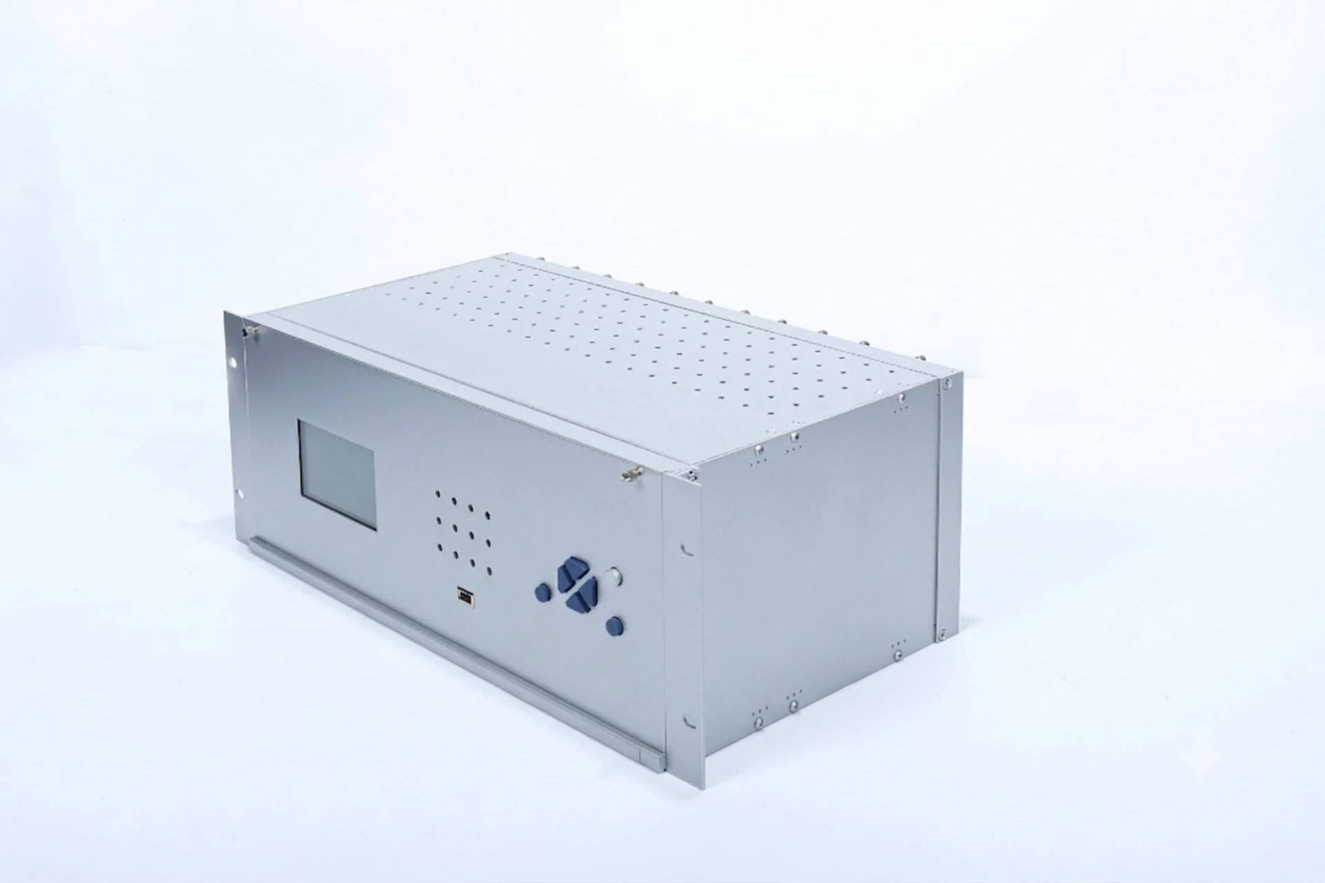
Measurement and Control Devices in Protection Relays: Functions and Types
What are measurement and control devices in a protection relay?
A measurement and control device is a bay-level IED that reads CT and VT inputs, computes the quantities an operator needs, drives breaker trip and close outputs, and reports to station SCADA over IEC 61850 or IEC 60870-5-104. A protection relay decides whether to trip; a meter only displays what it measured. They used to need two cubicles, and one bay unit now does both, saving wiring, drawings and panel space more than hardware price. Three standard families set the requirements: IEC 61850-8-1:2011+AMD1:2020 for the station bus, IEC 60870-5-103:1997 and IEC 60870-5-104:2006+AMD1:2016 for serial and TCP telecontrol, and IEC 60688:2024 for measurement accuracy. Device numbers come from ANSI/IEEE C37.2-2022. Units are classed by what they watch: line, main transformer or common bay. In an IEC 61850 digital station the unit exchanges sampled values, GOOSE trips and MMS metering with merging units and bay controllers; traditional stations use Modbus or DNP3. Setting review and quotation within 12 hours, MOQ 1, 7-15 working days.
Measurement and Control Devices at a Glance
Measurement and control devices are bay-level IEDs that read CT and VT inputs, work out the electrical quantities an operator needs, drive breaker trip and close outputs, and report everything to the station SCADA over IEC 61850 or IEC 60870-5-104.
A protection relay decides whether to trip. A meter only displays what it measured. Those two jobs used to need two cubicles; one bay unit now does both, and the saving lands mostly in wiring, drawings and panel space rather than in hardware price.
That is the whole argument for integrating them.
- Line bay unit: Ia/Ib/Ic, phase and line voltage, P, Q, cosφ; switches one breaker, one disconnector and one earth switch.
- Transformer bay unit: current and voltage on both sides, winding temperature and tap position; switches two breakers and drives tap raise/lower.
- Common unit: station services only, DC supply, auxiliary contacts and status inputs; no primary plant of its own.
- Measurement thread: 0.2S or 0.5S accuracy class on the metering inputs, quoted to IEC 60688:2024.
- Protection auxiliary thread: the same samples, fed to 50/51, 51N/51G and 87 elements inside the paired relay.
- Control outputs: dry contact to the breaker coil, or IEC 61850 GOOSE where the bay sits on a station bus.
- Time source: IRIG-B or PTP; without it, sequence-of-event records cannot be lined up across bays.
- Where it lives: the bay cubicle or switchgear panel, not the control room.
Three standard families set what these devices must do: IEC 61850-8-1:2011+AMD1:2020 for the station bus mapping, IEC 60870-5-103:1997 and IEC 60870-5-104:2006+AMD1:2016 for serial and TCP telecontrol, and IEC 60688:2024 for the accuracy classes quoted on the measurement inputs. Device numbers come from ANSI/IEEE C37.2-2022.
The sections below cover what a bay unit measures, how the sampling and logic chain runs, the control device types you will be asked to choose between, and what to check before specifying one.
What Are Measurement and Control Devices in Power Systems?
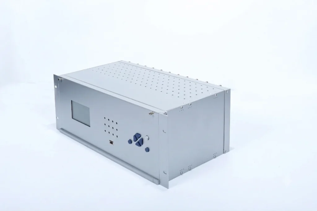
Substation units of this kind are intelligent electronic devices (IEDs) at the bay level of substation automation systems. Their core functions include collecting, processing and transmitting information from primary and secondary equipment, as well as receiving control commands to implement operation management of controlled targets.
Selecting a relay for a live project?
Send the system voltage, CT ratio and tripping scheme. Our engineers confirm the model and reply within 12 hours.
As the core carrier of measurement and control functions in substations, such devices are categorized into line measuring and control units, main transformer measuring and control units, common measuring and control units based on application scenarios. They serve as critical basic equipment supporting unattended operation and intelligent maintenance of substations.
Three types cover most bays.
Definition of Measurement and Control Devices in Protection Relays
A protection relay measurement & control unit is the embedded hardware and software module within numerical IEDs that performs real-time electrical data sampling, parameter calculation, local logic control, bidirectional data communication and unified control of monitoring and measuring devices; unlike old analog relays that only execute fault tripping, digital protection relays fold both functions into one compact unit, eliminating separate meters, transducers and local control panels.
Core Role Inside Intelligent Protection Relays
- Capture raw analog signals from CTs and VTs for protection fault judgment
- Output accurate metering data for energy statistics and load monitoring
- Execute circuit breaker opening/closing, interlock and bay-level logic
- Transmit real-time data, fault logs and event records to upper SCADA/EMS
- Support remote parameter setting, status feedback and automatic substation operation
Five jobs, one device.
Integration with SCADA & Digital Substation Automation
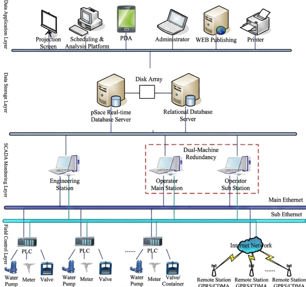
All measuring and control devices follow unified communication standards to connect with the station level of a substation automation system.
In IEC 61850 digital substations, relay measurement units exchange sampled values (SV), GOOSE trip signals and MMS metering data with merging units, bay control units and remote terminal units without hard-wired copper circuits.
For traditional substations, Modbus TCP/RTU, DNP3 and IEC 60870-5-104 are mainstream communication protocols supported by multifunction measurement relays.
The protocol choice sets the wiring.
Why Smart Grids Need Them
Smart grid construction requires full digitalization, unattended substation operation and predictive asset management of equipment assets.
Discrete analog meters and independent control switches fail to satisfy real-time monitoring demands. The all-in-one measuring and controlling devices in digital substations can minimize cabinet wiring, lower project engineering costs, and achieve closed-loop monitoring and control for power generation, transmission and distribution systems.
Working Principle of Measurement and Control Units
The whole workflow of a bay measurement and control unit can be divided into signal acquisition, digital processing, logic execution and data transmission four stages.
Electrical Signal Sampling (Current, Voltage, Frequency, Power)
CT secondary current and VT secondary voltage analog signals enter the measurement and control unit’s isolation sampling circuit. High-precision AD converters digitize them at microsecond intervals. The four quantities carried are phase current, voltage, frequency and the power derived from them.
Accuracy is quoted per input, not per device.
The embedded DFT algorithm computes fundamental electrical values, filters harmonic noise and delivers IEC 60688-compliant 0.2S/0.5S precision. It measures three-phase current, phase/line voltage, active/reactive power, power factor, frequency, harmonics and total energy.
Internal Signal Processing of Digital Protection Relays
After sampling, the CPU of the measurement and control module runs two parallel calculation threads:
- Measurement thread: Compute steady-state electrical quantities for daily monitoring and metering
- Protection auxiliary thread: Output instantaneous phasor data for differential, overcurrent, earth fault protection algorithms
All sampled data is stored in high-speed buffer memory for fault waveform recording and SOE event timestamping with 1ms precision.
Two threads, one sample buffer.
Control Logic & Circuit Breaker Trip/Close Execution
The control logic module receives local manual commands or remote SCADA control instructions.
After interlock condition verification (busbar voltage status, switch position, fault blocking signals), the unit outputs dry contact or GOOSE digital signals to drive circuit breakers, disconnectors and earthing switches. Interlocking logic (anti-tripping, parallel switch blocking, transformer inter-bay coordination) is fully configurable inside the bay unit without additional auxiliary relays.
Interlocks are the part that gets commissioned last.
Communication Interconnection with IEDs & Substation Control Systems
All measurement and control hardware embeds multi-protocol Ethernet serial communication interfaces:
- IEC 61850: GOOSE for fast inter-device control, MMS for metering report, SV for digital transformer signals
- Legacy protocols: Modbus TCP/RTU, DNP3, IEC 60870-5-103/104 for old SCADA system compatibility Time synchronization via IRIG-B or PTP ensures unified timestamp for all measurement data and fault events across the entire substation bay.
Main Functions of Measurement and Control Devices
Three jobs decide whether a bay unit earns its place: what it measures, what it switches, and what it reports upward. The lists below are the items to tick on a datasheet, in the order an EPC reviewer reads them.
The datasheet order matters here.
Protection Relay Measurement Functions: What the Relay Measures
Protection relay measurement functions fall into two groups: the quantities the operator reads every day, and the quantities that only matter during a disturbance. Both come from the same sample buffer.
| Measured quantity | Declared accuracy | What it feeds |
|---|---|---|
| Phase current Ia/Ib/Ic | 0.2S or 0.5S class | Load monitoring, energy settlement |
| Phase and line voltage | 0.2S or 0.5S class | 27 and 59 elements, power calculation |
| Active and reactive power | 0.5S class | Demand records, SCADA trending |
| Frequency | 0.01 Hz | 81 elements, load shedding schemes |
| Harmonics, 2nd to 31st order | Declared per device | Power quality checks, capacitor bank checks |
| Import and export energy | 0.2S or 0.5S class | Billing and settlement |
- 3-phase full electrical quantity measurement: Ia/Ib/Ic, Ua/Ub/Uc, line voltage
- Power calculation: Active power P, reactive power Q, apparent power S, power factor cosφ
- Grid quality monitoring: System frequency, 2–31 order harmonic voltage/current, unbalance degree
- Energy metering: Forward/reverse active/reactive energy cumulative statistics for settlement
- Load curve recording: Hourly/daily load storage for power demand analysis
Local & Remote Control Functions
- Circuit breaker control: Remote/local trip, close, lockout operation
- Switchgear auxiliary control: Disconnector, earthing switch remote switching
- Multi-layer interlock logic: User-configurable logic via relay configuration software
- Status feedback: Real-time upload of switch position, device fault, operation alarm signals
- Automatic sequence control: Bay-level auto reclosing, transformer load tap adjustment linkage
Five outputs, five checks.
Communication & Full Data Management
- Real-time measurement data periodic reporting to SCADA/EMS
- SOE sequence of event recording: All switching actions, protection start/trip events with high-precision timestamps
Why Global EPC Contractors Prefer Integrated Measurement & Control Protection Relays
For EPC companies undertaking cross-border grid, power plant and industrial energy projects, all-in-one protection relays with both functions built in bring four commercial benefits:
- Reduce engineering drawing workload: One device drawing replaces separate meter, relay and control schematic diagrams
- Simplify secondary cabinet layout: Less component layout design, smaller cabinet dimensions cut transportation costs
- Shorten site construction period: Less wiring work reduces on-site labor and commissioning cycle
- Realize cross-project standardization: Unified relay model for all feeder, transformer and generator bays, simplify spare parts inventory and global after-sales service
None of the four is a line on a datasheet. All four are schedule and drawing effects, which is why they decide tenders where the relay specifications are already equal.
Control Device Types: Line, Transformer and Common Units
Suppliers quote three control device types, and the difference is the bay each one is wired into rather than the hardware inside.
| Type | Wired to | Measures | Switches | ANSI functions in the paired relay |
|---|---|---|---|---|
| Line bay unit | One feeder or incoming cable | Ia/Ib/Ic, voltage, P, Q, cosφ, f | One breaker, one disconnector, one earth switch | 50/51, 50N/51N, 79 |
| Transformer bay unit | HV and LV windings of one transformer | Two-side current and voltage, winding temperature, tap position | Two breakers, tap changer raise and lower | 87T, 50/51, 49, 26 |
| Common unit | Station services, not a primary bay | DC supply voltage, auxiliary contacts, temperature and status inputs | No primary plant; alarms and indication only | None of its own |
Ask which type the quotation covers. A common unit priced against a line bay unit is the mismatch that turns up most often in MV tenders.
FAQ
Q1: What is a measurement and control device in a protection relay?
It refers to the integrated hardware and software module inside numerical protection IEDs that completes real-time electrical quantity measurement, bay-level circuit breaker control, interlock logic execution and data communication with SCADA systems, combining the functions of independent power meters, transducers and local control panels into a single protection relay.
Q2: What is the difference between an RTU and protection relay built-in measurement units?
An RTU is a centralized multi-bay data collection device without complete power protection algorithms, mainly used for distribution station signal aggregation. The units built into protection relays are bay-dedicated, paired with matching protection logic to realize synchronous measurement and fault tripping for one primary equipment bay, with faster response speed and higher data coordination.
Q3: Can one integrated protection relay replace separate meters and control units?
Yes. Modern multifunction digital protection relays embed high-precision measurement modules and full control logic, fully replacing standalone multi-function power meters, current/voltage transducers and local control switches, which has become the standard secondary equipment solution for new EPC power projects worldwide.
Q4: Which communication protocols do bay units commonly support?
Main standards include IEC 61850 (digital substations), Modbus TCP/RTU, DNP3, IEC 60870-5-104, and time synchronization protocols IRIG-B/PTP for unified timestamp of all measurement and fault data.
Q5: How to select measurement and control devices for medium voltage switchgear applications?
Select compact multifunction measurement relays with Class 0.5S measurement accuracy, support for 1A/5A CT secondary signals, Modbus + IEC 61850 dual communication, and complete feeder protection elements (overcurrent, earth fault, reclosing logic) matching local grid voltage standards and EPC project automation requirements.
Conclusion
Measurement and control devices are no longer auxiliary accessories of protection relays, but core functional modules that determine the automation level, operation accuracy and total project cost of a power system.
Digital integrated multifunction measurement relays have completely replaced discrete analog secondary equipment, becoming the standard configuration of smart grids, digital substations, power plants and renewable energy projects.
For EPC contractors, power station operators and procurement managers, selecting reliable, multi-protocol compatible, high-precision protection relays with the two functions integrated can effectively reduce engineering, construction and maintenance costs while improving the safety and automation performance of the entire power system.
CTA
Send the bay list, the CT and VT ratios and the protocol your station SCADA speaks. The engineering team returns a device schedule, an I/O list and a setting sheet you can price against, for EPC grid, hydropower, wind and solar projects.
Our technical team supports one-stop scheme design, parameter configuration and after-sales commissioning services. Contact us now to get technical datasheets and project quotation.
Related Reading
Seven pages on this site go deeper on the parts touched above: where the bay unit sits in a distribution room, the three device types you can buy, the standalone instruments a bay unit replaces, and the protocol choice on the station bus.
- Secondary equipment in distribution rooms: where the bay unit sits among the meters, RTUs and DC supply.
- Intelligent 246H integrated measurement and control device: the bay unit itself, with the input and output count.
- Common measurement and control panel: the station-services variant when the scope covers services rather than a bay.
- Digital multifunction power meter: the standalone meter a bay unit replaces.
- Phasor measurement unit: synchrophasors when the scheme needs wide-area measurement rather than bay measurement.
- Online power quality analyzer: where harmonic and disturbance recording is the main duty.
- Modbus and IEC 61850 compared: which protocol carries which job on the station bus.
Technical References
Every edition below was checked against the publisher catalogue. Datasheets still in circulation cite IEC 60688:2012, which was withdrawn on 2021-09-16.
| Source | What it covers | Type | Edition |
|---|---|---|---|
| IEC 61850-8-1 | MMS mapping to the station bus, including GOOSE and sampled values | International Standard | 2011+AMD1:2020 |
| IEC 60870-5-103 | Serial information interface for protection equipment | International Standard | 1997 |
| IEC 60870-5-104 | Telecontrol over TCP/IP for older SCADA masters | International Standard | 2006+AMD1:2016 |
| IEC 60688 | Accuracy classes and test methods for measuring transducers | International Standard | 2024 |
| IEC 60255-1 | General requirements for measuring relays and protection equipment | International Standard | 2022 |
| IEC 61869-2 | Current transformer accuracy classes, including 5P20 for protection duty | International Standard | 2012 |
| ANSI/IEEE C37.2 | Device numbers: 26, 49, 50/51, 79, 87 | Standard | 2022 |
Protection CTs are specified to 5P or 10P classes, not to 0.2S or 0.5S. Those two belong to the metering side and will saturate under fault current.
About Author

Hello, I'm Leon Zhang. I have 15 years of experience in the power relay protection industry with extensive pre-sales and after-sales project experience. Our company specializes in various complete sets of relay protection and automation equipment. I can assist customers in solving all practical on-site project challenges and provide optimal integrated solutions.
Tell Us Your Requirement



High Quality
Stable performance, reliable design, ensuring safe operation for power system protection and grid stability.
Fast Delivery
Timely delivery to support your urgent orders and project schedules efficiently and professionally at any time.
Best Warranty
Professional Warranty: Reliable after-sales support for stable relay protection and long-term customer satisfaction.