

-
Leon Zhang sales consultant
-
Email: zxl635973785@gmail.com
-
Phone/WhatsApp: +86 13655813266
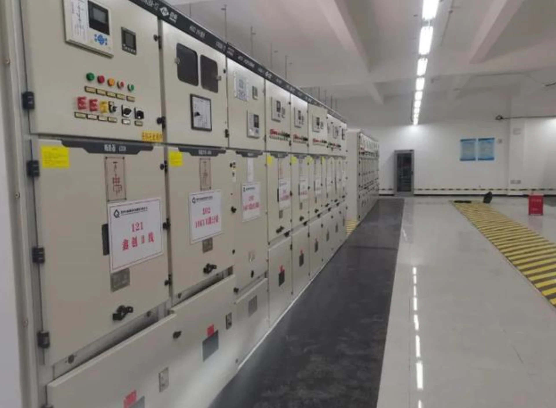
Distribution Room Secondary Equipment: Types, Functions and Applications
Secondary equipment in a distribution room consists of protection, measurement, control, communication and automation devices that monitor and control the electrical distribution system. Unlike primary equipment such as transformers, circuit breakers and busbars, secondary equipment processes electrical signals, executes protection logic, records operating data and communicates with control systems.
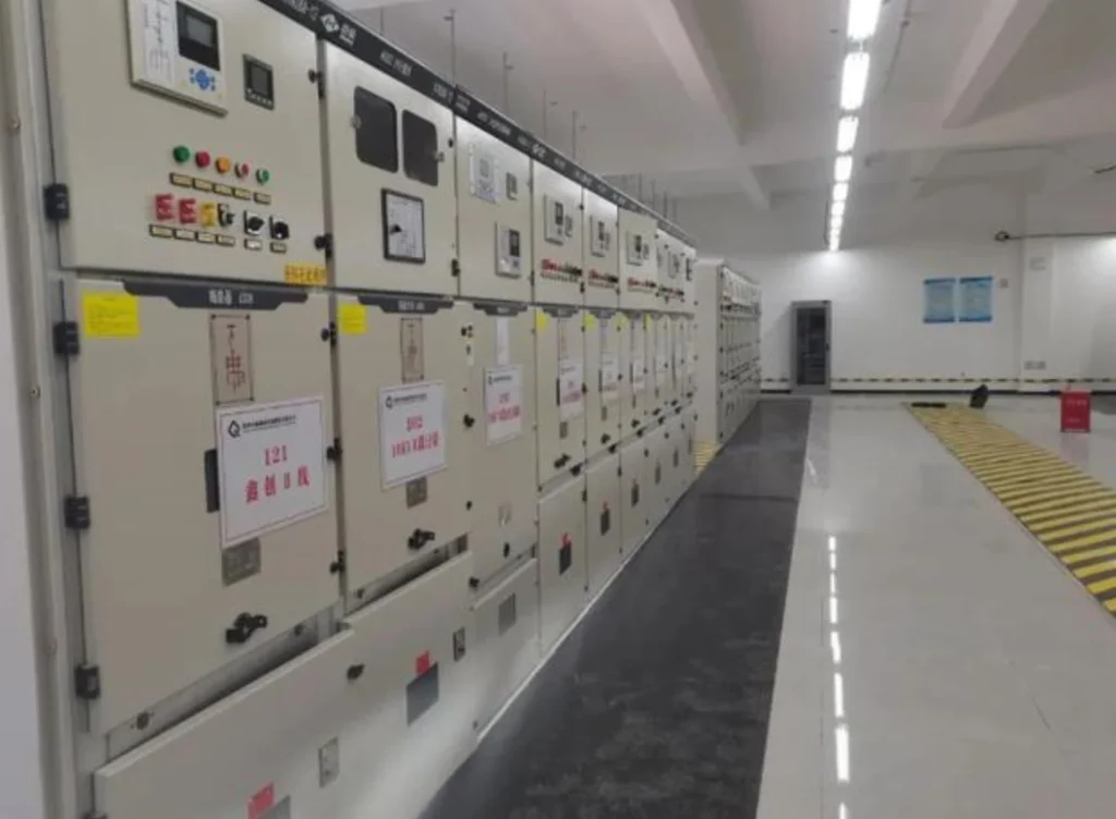
Distribution room secondary equipment works in tandem to complete data acquisition, fault protection, remote monitoring, and command transmission. It enables unattended operation, precise maintenance, and rapid fault handling, greatly boosting the overall efficiency of the power distribution system.
Secondary equipment including DTU terminals and various power protection relays is the core guarantee for safe, efficient and intelligent operation of modern power distribution rooms.
What Is Secondary Equipment in a Distribution Room?
Secondary equipment refers to the electrical protection, measurement, control, monitoring, communication and automation devices used to monitor and manage primary electrical equipment.
| Primary Equipment | Secondary Equipment |
|---|---|
| Transformer | Protection Relay |
| Circuit Breaker | Measurement Device |
| Busbar | RTU / FTU / DTU |
| Cable | SCADA |
| Switchgear | Communication Gateway |
| CT / VT | Control & Monitoring System |
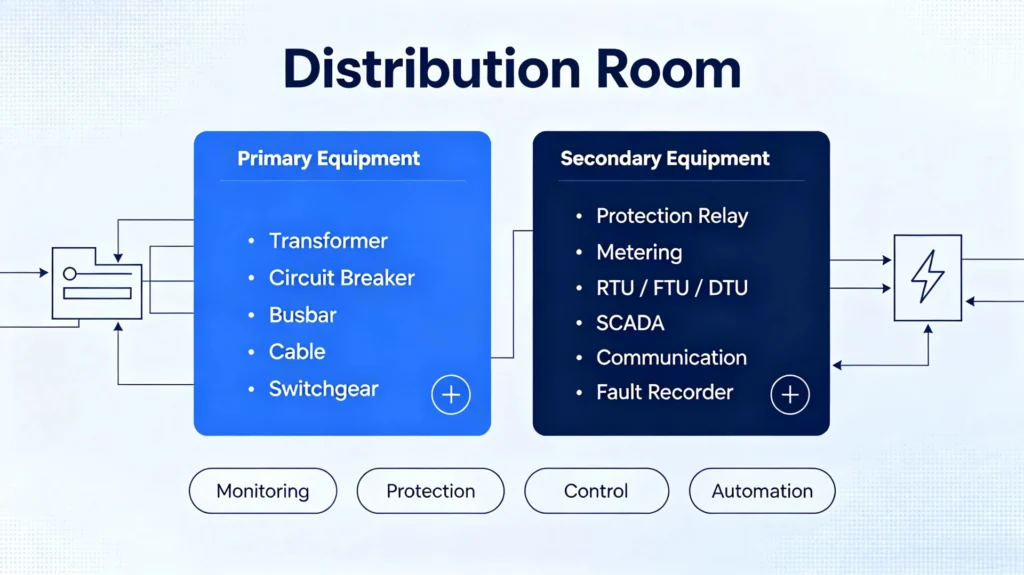
Types of Secondary Equipment in Distribution Rooms
Secondary equipment in a distribution room refers to all low-voltage devices that monitor, control, protect, and communicate with the primary power system. While primary equipment such as transformers, circuit breakers, and busbars handle the actual power flow, secondary equipment processes signals, executes protection logic, records operational data, and enables remote control .
Below are the seven main categories of secondary equipment you will find in a modern distribution room.
1. Protection Relays
Protection relays are the most critical secondary devices in any distribution room. They continuously monitor electrical parameters — current, voltage, frequency, and phase angle — and issue trip or alarm commands when abnormal conditions are detected .
Common types of protection relays:
| Relay Type | ANSI Code | Application |
|---|---|---|
| Overcurrent Protection Relay | 50/51 | Detects excessive current from short circuits or overloads |
| Earth Fault Protection Relay | 50N/51N | Detects phase-to-ground leakage currents |
| Feeder Protection Relay | — | Protects distribution feeders with multiple functions |
| Transformer Protection Relay | — | Differential and backup protection for power transformers |
| Motor Protection Relay | — | Protects motors from overload, stall, and unbalance |
| Differential Protection Relay | 87 | Compares currents entering and leaving a protected zone |
| Directional Protection Relay | 67/67N | Detects fault direction in looped networks |
| Generator Protection Relay | — | Protects generators from internal and external faults |
Modern numerical relays combine multiple protection functions in a single device, replacing racks of discrete electromechanical relays . This makes them ideal for space-constrained distribution rooms.
2. Measurement and Metering Equipment
Measurement devices provide real-time data on system performance and energy consumption. They are essential for billing, load management, and power quality assessment.
Key devices include:
- Multifunction Power Meter — Measures current, voltage, power, frequency, and power factor
- Energy Meter — Records active and reactive energy consumption
- Power Quality Analyzer — Monitors harmonics, sags, swells, and transients
- Voltage Measurement — PT-based or direct voltage sensing
- Current Measurement — CT-based current sensing
- Frequency Measurement — Monitors system frequency stability
- Power Factor Measurement — Critical for reactive power management
These devices provide the data needed for load profiling, demand forecasting, and energy efficiency improvements.
3. Distribution Automation Terminals
Distribution automation terminals are the brains of a modern distribution network. They enable unattended operation, remote control, and rapid fault handling .
| Terminal Type | Full Name | Primary Function |
|---|---|---|
| FTU | Feeder Terminal Unit | Mounted on pole-mounted switches (10kV breakers, load switches). Collects electrical parameters, monitors line status, and executes remote open/close commands |
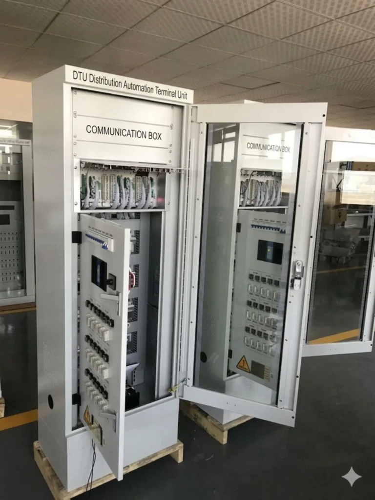
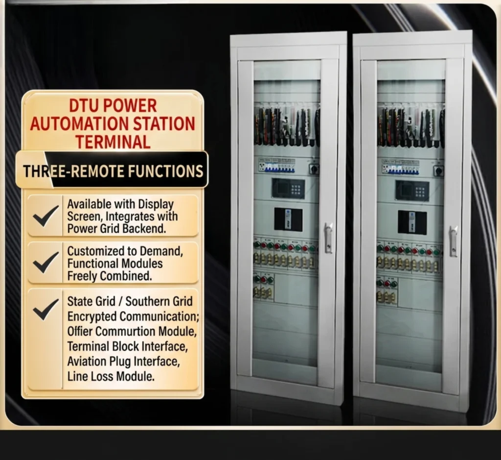
| DTU | Distribution Terminal Unit | Installed in ring main units, switching stations, and compact substations. Collects switch position signals, voltage, current, and power data. Performs fault identification, isolation, and non-fault zone restoration |
| TTU | Transformer Terminal Unit | Installed at distribution transformers. Monitors transformer operating conditions — voltage, current, power, energy. Records historical data for load analysis and fault detection |
| RTU | Remote Terminal Unit | Basic automation unit for monitoring and controlling transformers, breakers, reclosers, sectionalizers, and capacitor banks. Communicates with the master station to provide operational data and execute control commands |
In the distribution automation hierarchy: Master Station → Substation → FTU/DTU/TTU work together to enable fault detection, isolation, and service restoration .
4. Control and Monitoring Equipment
Control equipment allows operators to manage the distribution system locally or remotely. These devices provide the human-machine interface and logic processing for system operations.
Key components:
- Control Panels — House switches, indicators, and control circuits
- PLC (Programmable Logic Controller) — Executes automation logic for switching and interlocking
- HMI (Human-Machine Interface) — Touchscreen or display panels for local operation
- Remote I/O — Distributed input/output modules for signal acquisition
- Alarm Panels — Visual and audible alarms for abnormal conditions
- Interlocking Devices — Prevent unsafe operations (e.g., closing a breaker while a ground switch is closed)
These devices work together to ensure safe, reliable, and operator-friendly control of the distribution system .
5. Communication Equipment
Communication equipment enables data exchange between protection relays, automation terminals, SCADA systems, and control centers. Modern distribution rooms rely on robust communication networks for real-time monitoring and control .
Key devices and protocols:
| Device / Protocol | Purpose |
|---|---|
| Industrial Ethernet Switch | Backbone for substation communication networks |
| Communication Gateway | Protocol conversion between different systems |
| Fiber Optic Communication | High-speed, interference-free data transmission |
| RS485 | Serial communication for legacy devices |
| Modbus RTU/TCP | Widely used for SCADA integration |
| IEC 61850 | International standard for substation communication — supports GOOSE messaging for high-speed peer-to-peer protection signals |
| IEC 60870-5-103/104 | Telecontrol protocols for utility communication |
Communication protocols are selected according to the substation automation architecture and project requirements. IEC 61850 is increasingly preferred for its interoperability and high-speed capabilities .
6. Fault Recording Equipment
Fault recording devices capture detailed data when a fault occurs. This data is invaluable for post-fault analysis, identifying root causes, and improving protection settings .
Key devices:
- Fault Recorder — Captures waveforms during system disturbances
- Disturbance Recorder — Records voltage and current variations
- Event Recorder — Logs sequence of events (trip signals, breaker operations)
- SOE (Sequence of Events) — Time-stamped record of all digital state changes
These devices help engineers analyze fault behavior, verify relay operation, and optimize protection coordination.
7. DC and Auxiliary Power Equipment
DC and auxiliary power equipment provide the reliable power supply that all secondary devices depend on. This category is often overlooked but is critical for system reliability — especially during AC supply loss .
Key components:
- DC Panel — Distributes DC power to protection and control circuits
- Battery Charger — Converts AC to DC and maintains battery charge
- Station Battery — Provides backup DC power during AC failure
- UPS (Uninterruptible Power Supply) — Ensures continuous AC power for critical loads (PCs, servers, communication gear)
- DC Monitoring — Monitors battery voltage, current, and health status
In a typical secondary equipment room, you will find protection panels, fault recorders, metering panels, power quality monitors, DC panels, and UPS units all housed together .
Summary Table
| Category | Key Devices | Primary Purpose |
|---|---|---|
| Protection Relays | Overcurrent, Earth Fault, Feeder, Transformer, Motor, Differential, Directional | Detect faults and issue trip commands |
| Measurement & Metering | Power Meter, Energy Meter, Power Quality Analyzer | Monitor system parameters and energy consumption |
| Distribution Automation | FTU, DTU, TTU, RTU | Enable remote monitoring, control, and fault handling |
| Control & Monitoring | Control Panels, PLC, HMI, Remote I/O, Alarm Panels | Provide local and remote system control |
| Communication | Ethernet Switches, Gateways, Fiber Optic, Modbus, IEC 61850 | Enable data exchange and SCADA integration |
| Fault Recording | Fault Recorder, Disturbance Recorder, Event Recorder, SOE | Capture data for post-fault analysis |
| DC & Auxiliary Power | DC Panel, Battery Charger, Station Battery, UPS, DC Monitoring | Ensure reliable power supply to all secondary devices |
How Does Secondary Equipment Work in a Distribution Room?
Secondary equipment in a distribution room does not operate in isolation — it functions as an integrated chain that transforms raw electrical signals into actionable intelligence, enabling both local protection and remote control.
Below is the typical data and control flow from the primary power system to the control center.
The Workflow
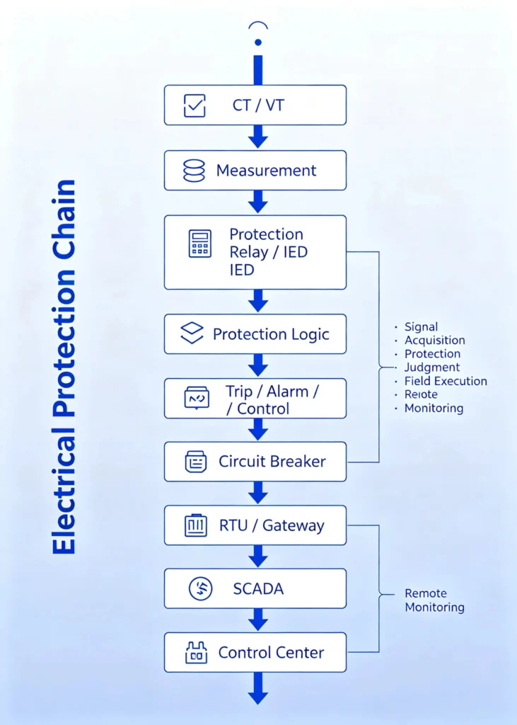
Step-by-Step Breakdown
Step 1 — Signal Acquisition
Devices involved: CT (Current Transformer), VT (Voltage Transformer)
The CTs and VTs step down high primary current and voltage to safe, standardized secondary values (e.g., 5A / 1A for current, 100V / 110V for voltage). These analog signals represent the real-time electrical condition of the feeder.
These signals are the foundation for everything that follows — protection, measurement, and control all depend on accurate CT/VT inputs.
Step 2 — Protection and Measurement
Devices involved: Protection Relays / IEDs, Multifunction Meters, Power Quality Analyzers
The analog signals are fed into protection relays and measurement devices:
- Relays / IEDs digitize the signals, calculate RMS values, and continuously compare them against preset thresholds (e.g., overcurrent pickup, earth fault sensitivity).
- Meters display real-time values — current, voltage, power, frequency, power factor — for local reading and remote transmission.
If a fault is detected, the relay is ready to act. If the system is healthy, measurement devices log data for monitoring and analysis.
Step 3 — Local Control
Devices involved: Protection Relays, PLCs, Control Panels, HMI
When the relay’s protection algorithm identifies a fault condition, it issues a trip command to the associated circuit breaker. This is the critical action that isolates the fault and protects the system.
Control actions include:
- Trip — Open the circuit breaker to isolate the fault
- Close — Re-energize the feeder after fault clearance (manual or auto-reclose)
- Alarm — Notify operators of abnormal conditions without tripping
- Interlock — Prevent unsafe operations (e.g., closing a breaker with a ground switch still engaged)
Local control devices ensure the distribution system reacts immediately to faults — even when communication to the control center is lost.
Step 4 — Data Communication
Devices involved: RTU, Communication Gateway, Industrial Ethernet Switch, Fiber Optic
Once the local protection and measurement devices have processed the data, it needs to be transmitted to the control center. This is where the communication infrastructure comes in.
- RTU (Remote Terminal Unit) or DTU (Distribution Terminal Unit) collects data from multiple IEDs and protection relays.
- Communication gateways convert protocols between different devices (e.g., Modbus to IEC 61850).
- Ethernet switches and fiber optic provide high-speed, reliable data transmission — often with redundancy for critical applications.
Common communication protocols used at this stage:
- Modbus RTU/TCP — Simple, widely supported
- IEC 61850 — Advanced, interoperable, with GOOSE for fast peer-to-peer signals
- IEC 60870-5-103/104 — Utility-standard telecontrol protocols
- DNP3 — Common in North American utilities
The communication layer is what transforms a traditional distribution room into a smart, connected substation.
Step 5 — Remote Monitoring and Control
Devices involved: SCADA System, Control Center
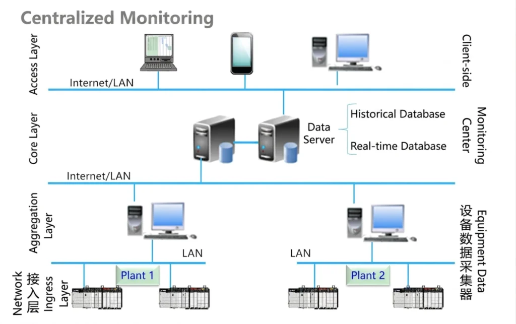
At the top of the chain, the SCADA (Supervisory Control and Data Acquisition) system receives all data from the distribution room:
- Real-time analog values (current, voltage, power, etc.)
- Status indicators (breaker open/closed, relay healthy/alarm)
- Event records (trip signals, fault logs, SOE)
- Waveform data (from disturbance recorders)
SCADA displays this information to operators on a human-machine interface (HMI) — typically a graphical screen showing the single-line diagram of the distribution network.
Operators can:
- Monitor system status in real time
- Respond to alarms and faults
- Issue remote control commands (open/close breakers)
- Analyze historical data and event records
- Optimize system performance and load management
SCADA integration enables unattended operation — distribution rooms that run automatically with minimal human intervention.
Summary: From Signal to Action
| Step | Function | Key Device | Action |
|---|---|---|---|
| 1 | Signal Acquisition | CT / VT | Steps down high voltage/current to safe levels |
| 2 | Processing | Relay / IED / Meter | Calculates values and compares against settings |
| 3 | Local Control | Relay / PLC | Issues trip, close, or alarm commands |
| 4 | Communication | RTU / Gateway / Switch | Transmits data to control center |
| 5 | Remote Monitoring | SCADA / Control Center | Operators monitor and control the system |
Why This Flow Matters
Understanding this sequence is essential for engineers, system integrators, and plant operators because it highlights:
- How protection is executed locally — even without communication, relays will trip for faults
- How data flows to the control center — enabling remote visibility and control
- How the system achieves coordination — each step depends on the previous one; a failure at any point affects the entire chain
In modern distribution rooms, secondary equipment is not just a collection of devices — it is a system-of-systems designed for safety, reliability, and intelligence.
Primary Equipment vs Secondary Equipment
| Feature | Primary Equipment | Secondary Equipment |
|---|---|---|
| Main Purpose | Power transmission/distribution | Protection, control and monitoring |
| Typical Equipment | Transformer, CB, Busbar | Relay, Meter, RTU, SCADA |
| Carries Main Power | Yes | Generally no |
| Fault Detection | Indirect | Yes |
| Control | Mechanical/electrical | Logic/software based |
| Communication | Usually limited | Common |
| Automation | Limited | Core function |
Primary equipment handles the electrical power path, while secondary equipment monitors, protects, controls and communicates with the primary system.
Functions of Distribution Room Secondary Equipment
Secondary equipment in a distribution room serves six core functions that work together to ensure safe, reliable, and intelligent power distribution.
1. Protection
Detect electrical faults and initiate tripping.
Protection relays continuously monitor current, voltage, frequency, and phase angle. When a fault occurs — such as overcurrent, short circuit, earth fault, or overvoltage — the relay issues a trip command to the circuit breaker, isolating the faulty section before damage can spread.
Key devices: Protection Relays (Overcurrent, Earth Fault, Differential, Directional), Breaker Failure Relays
Protection is the primary function of secondary equipment — it prevents equipment damage, ensures personnel safety, and maintains system stability.
2. Measurement
Measure voltage, current, power, energy, and power quality.
Measurement devices provide real-time data on system performance. This data is used for:
- Load monitoring and demand forecasting
- Energy billing and consumption analysis
- Power quality assessment (harmonics, sags, swells)
- System efficiency optimization
Key devices: Multifunction Power Meters, Energy Meters, Power Quality Analyzers, CTs/VTs
Accurate measurement is the foundation for informed decision-making — both for operators and for automated control systems.
3. Control
Control circuit breakers, switches, and other equipment.
Control devices enable operators to open and close breakers and switches — either locally at the panel or remotely from a control center. Control functions include:
- Manual open/close commands
- Automatic switching based on protection logic
- Interlocking to prevent unsafe operations
- Auto-reclosing after transient faults
Key devices: Control Panels, PLCs, HMI, Remote I/O, Relay Output Contacts
Control is how the system acts — transforming protection decisions into physical switching actions.
4. Monitoring
Monitor operating status and alarms.
Monitoring devices continuously track the state of the distribution system:
- Breaker position (open/closed)
- Relay health and self-diagnostic status
- Alarm conditions (overload warning, earth fault alarm)
- System voltage and current trends
Monitoring provides operators with visibility into system status — enabling rapid response to abnormal conditions.
Key devices: Alarm Panels, HMI, SCADA Front-End, Status Indicators
You cannot manage what you cannot see — monitoring provides the situational awareness needed for effective system management.
5. Communication
Transmit data to SCADA and control centers.
Communication devices and protocols enable the exchange of data between local secondary equipment and remote control centers. This includes:
- Real-time analog values (current, voltage, power)
- Status indicators (breaker position, relay flags)
- Event records (trips, alarms, SOE)
- Remote control commands (open/close)
Key devices: RTU, DTU, Communication Gateway, Ethernet Switch, Fiber Optic
Common protocols: Modbus RTU/TCP, IEC 61850, IEC 60870-5-103/104, DNP3
Communication transforms a traditional distribution room into a smart, connected asset — enabling automation and remote management.
6. Automation
Support fault detection, isolation, restoration, and remote operation.
Automation is the integration layer that ties all other functions together. It enables the distribution system to act without human intervention in certain scenarios:
- Fault Detection — Identify fault type and location
- Fault Isolation — Open the correct breaker to isolate only the faulty zone
- Service Restoration — Re-energize healthy sections after fault clearance
- Remote Operation — Execute commands from the control center
- Unattended Operation — Run the distribution room with minimal on-site personnel
Key devices: Distribution Automation Terminals (FTU, DTU, TTU, RTU), SCADA Systems, PLCs
Automation is what enables the smart grid — improving reliability, reducing outage times, and lowering operational costs.
Summary Table: Six Core Functions
| Function | Purpose | Key Devices | Outcome |
|---|---|---|---|
| Protection | Detect faults and initiate tripping | Protection Relays, 50BF | Equipment safety, personnel protection |
| Measurement | Monitor voltage, current, power, energy | Meters, PQ Analyzers, CT/VT | Load management, billing, efficiency |
| Control | Open/close breakers and switches | Control Panels, PLC, HMI, Remote I/O | Physical switching actions |
| Monitoring | Track operating status and alarms | Alarm Panels, HMI, Status Indicators | Situational awareness |
| Communication | Transmit data to SCADA and control centers | RTU, Gateway, Switches, Fiber | Remote visibility and control |
| Automation | Enable fault detection, isolation, restoration, remote operation | FTU, DTU, TTU, RTU, SCADA | Smart grid, unattended operation |
Secondary Equipment for Smart Distribution Rooms
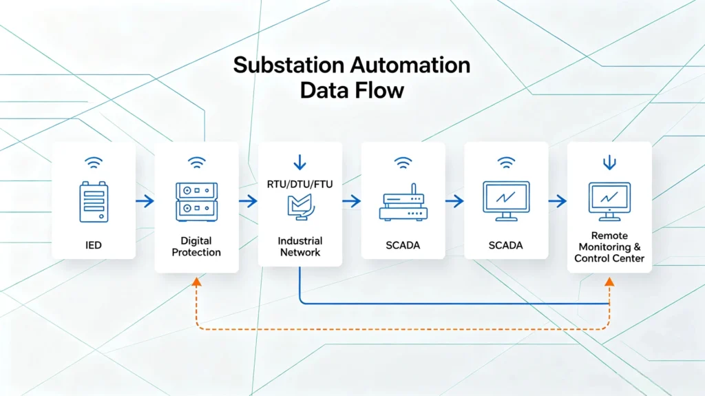
Modern distribution rooms are evolving from isolated, manually operated setups into fully integrated digital systems — combining protection relays, intelligent electronic devices (IEDs), RTUs, communication gateways, power quality monitors, and SCADA into a unified network.
This shift is not just about technology — it is about reliability, efficiency, and intelligence.
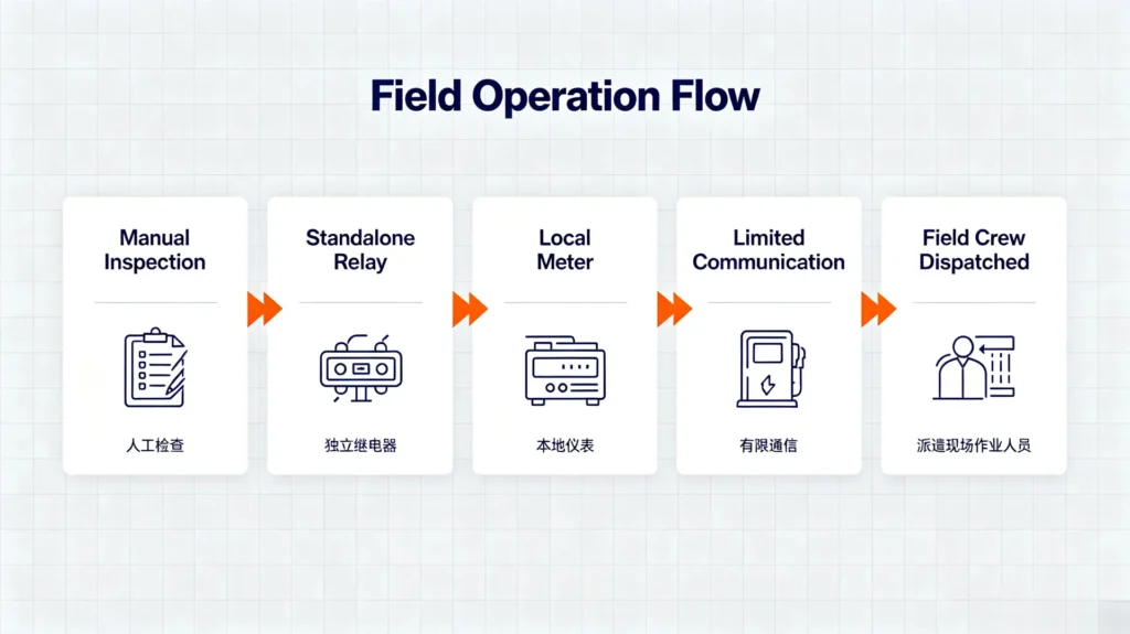
Traditional vs. Smart Distribution Room
| Aspect | Traditional | Smart |
|---|---|---|
| Monitoring | Manual inspection | Real-time remote monitoring |
| Protection | Standalone relay | Digital relay with communication |
| Control | Local manual | Remote and automated |
| Communication | Limited or none | High-speed industrial network |
| Fault Handling | Field crew dispatched | Instant detection and isolation |
| Data | Paper logs | Automated logging and analytics |
Workflow Comparison
Traditional Distribution Room:
Smart Distribution Room:
Key Technologies Enabling Smart Distribution
1. Intelligent Electronic Devices (IEDs)
Microprocessor-based devices that combine protection, control, measurement, and communication in a single unit. IEDs provide self-diagnostics, event recording, and network connectivity.
2. Digital Protection
Digital relays offer multiple protection functions in one device, programmable logic, self-diagnostics, waveform capture, and remote setting adjustments — capabilities that traditional electromechanical relays cannot provide.
3. Distribution Automation Terminals
| Device | Function |
|---|---|
| RTU | Data acquisition and remote control at substations |
| DTU | Communication and data transmission at ring main units |
| FTU | Feeder monitoring and automation on pole-mounted switches |
| TTU | Transformer condition monitoring |
4. Communication Network
Robust communication infrastructure with fiber optic, industrial Ethernet, and gateways. Protocols include IEC 61850 (with GOOSE for fast peer-to-peer signals), Modbus RTU/TCP, IEC 60870-5-103/104, and DNP3.
5. SCADA and Remote Monitoring
SCADA provides:
- Real-time visualization with live data
- Alarm management and event logging
- Historical data trending and analysis
- Remote open/close control
- Automated reporting
6. Power Quality Monitoring
Dedicated monitoring for harmonics, voltage sags/swells, flicker, and power factor — helping identify issues before they cause equipment damage or production interruptions.
The Business Value
| Benefit | Impact |
|---|---|
| Reduced downtime | Faster fault detection and restoration |
| Lower operational costs | Unattended operation, fewer site visits |
| Improved safety | Remote control reduces personnel exposure |
| Better asset management | Data-driven maintenance decisions |
| Enhanced reliability | Proactive issue identification |
| Future-ready | Supports renewables and EV charging integration |
Conclusion
The transition to smart distribution rooms transforms the system from:
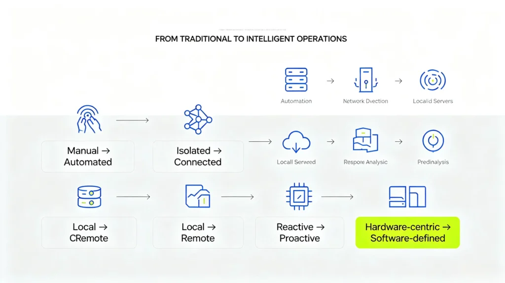
By integrating IEDs, digital protection, automation terminals, communication networks, SCADA, and power quality monitoring, smart distribution rooms deliver:
- More reliability — Faster fault response
- More efficiency — Lower operational costs
- More intelligence — Data-driven decisions
- More sustainability — Renewable energy ready
Smart distribution rooms are not a future concept — they are today’s standard for utilities, industrial plants, and commercial facilities seeking better reliability, efficiency, and control.
How to Select Secondary Equipment for a Distribution Room?
| Requirement | Recommended Equipment |
|---|---|
| Feeder Protection | Feeder Protection Relay |
| Transformer Protection | Transformer Protection Relay |
| Motor Protection | Motor Protection Relay |
| Energy Measurement | Multifunction Meter |
| Power Quality | Power Quality Analyzer |
| Remote Monitoring | RTU / DTU |
| Feeder Automation | FTU |
| Fault Recording | Fault Recorder |
| Communication | Gateway / Industrial Switch |
| Central Monitoring | SCADA |
| Backup DC Power | DC Panel / UPS |
Secondary Equipment in Distribution Room FAQ
1. What is secondary equipment in a distribution room?
Secondary equipment refers to all low-voltage devices in a distribution room that monitor, control, protect, and communicate with the primary power system. Unlike primary equipment (transformers, circuit breakers, busbars) that handle the actual power flow, secondary equipment processes electrical signals, executes protection logic, records operational data, and enables remote control.
Common examples: Protection relays, multi-function meters, RTUs, communication gateways, and SCADA systems.
2. What are the main types of distribution room secondary equipment?
Secondary equipment falls into seven main categories:
| Category | Examples |
|---|---|
| Protection Relays | Overcurrent, Earth Fault, Feeder, Transformer, Motor, Differential, Directional relays |
| Measurement & Metering | Multi-function power meters, energy meters, power quality analyzers |
| Distribution Automation | RTU, DTU, FTU, TTU |
| Control & Monitoring | Control panels, PLC, HMI, remote I/O, alarm panels |
| Communication | Ethernet switches, communication gateways, fiber optic, RS485 |
| Fault Recording | Fault recorders, disturbance recorders, event recorders, SOE |
| DC & Auxiliary Power | DC panels, battery chargers, station batteries, UPS, DC monitoring |
3. What is the difference between primary and secondary electrical equipment?
| Aspect | Primary Equipment | Secondary Equipment |
|---|---|---|
| Function | Handles main power flow | Monitors, controls, and protects primary equipment |
| Voltage Level | High voltage (6–35 kV and above) | Low voltage (typically 48V, 110V, 220V DC) |
| Examples | Transformers, circuit breakers, busbars, CTs/VTs | Protection relays, meters, RTUs, SCADA |
| Role | Carries and switches high power | Processes signals and executes logic |
Key point: Primary equipment carries the power; secondary equipment protects and controls it.
4. What does a protection relay do in a distribution room?
A protection relay continuously monitors current, voltage, frequency, and phase angle, and issues a trip or alarm command when an abnormal condition is detected.
Key functions:
- Fault detection (overcurrent, short circuit, earth fault, overvoltage, etc.)
- Trip command — open circuit breaker to isolate the fault
- Alarm output — notify operators of abnormal conditions
- Event recording — save fault data for post-analysis
- Coordination — ensure selective tripping with downstream devices
Protection relays are the most critical secondary devices — the first line of defense against electrical faults.
5. What are the roles of RTU, FTU, and DTU in distribution automation?
| Device | Full Name | Primary Function | Typical Installation |
|---|---|---|---|
| RTU | Remote Terminal Unit | Data acquisition and remote control; communicates with SCADA | Substations, distribution facilities |
| DTU | Distribution Terminal Unit | Collects switch status, voltage, current; fault detection and isolation | Ring main units, compact substations |
| FTU | Feeder Terminal Unit | Monitors feeder parameters; executes remote open/close commands | Pole-mounted switches, 10kV breakers |
| TTU | Transformer Terminal Unit | Monitors transformer conditions (voltage, current, load, temperature) | Distribution transformers |
In the distribution automation hierarchy: SCADA → Substation → RTU/DTU/FTU work together for fault detection, isolation, and service restoration.
6. How does secondary equipment communicate with SCADA?
Communication flow:
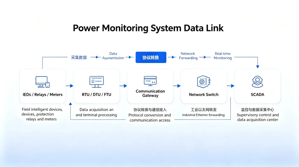
Common communication protocols:
| Protocol | Application |
|---|---|
| Modbus RTU/TCP | Simple, widely supported, legacy integration |
| IEC 61850 | Advanced substation automation; supports GOOSE for high-speed signals |
| IEC 60870-5-103/104 | Utility telecontrol standard |
| DNP3 | Common in North American utilities |
Data transmitted: Real-time analog values (current, voltage, power), status indicators (breaker position), event records (trips, alarms, SOE), waveform data, remote control commands.
Communication transforms a traditional distribution room into a smart, connected asset — enabling remote visibility, control, and automation.
7. What equipment is required for a smart distribution room?
| Component | Purpose |
|---|---|
| IEDs / Digital Protection Relays | Intelligent fault detection and trip execution |
| RTU / DTU / FTU | Remote data acquisition and control |
| Multi-function Meters | Real-time measurement of current, voltage, power, energy |
| Power Quality Analyzer | Monitor harmonics, sags, swells, and transients |
| Communication Gateway | Protocol conversion and network integration |
| Industrial Ethernet Switch | High-speed, reliable network backbone |
| SCADA System | Centralized monitoring, control, and data management |
| Fault / Disturbance Recorder | Capture data for post-fault analysis |
| DC Panel + UPS | Reliable power supply for all secondary devices |
All devices must be network-connected with real-time data exchange capability — typically using IEC 61850 or Modbus over Ethernet.
8. How do I select secondary equipment for a distribution room?
Step 1 — Define System Parameters
- Voltage level (6kV, 11kV, 22kV, 33kV, etc.)
- System grounding (solid, impedance, ungrounded)
- Fault current levels
- Load profile and criticality
Step 2 — Identify Protection Functions Required
- Overcurrent (50/51) — always required
- Earth Fault (50N/51N) — required for most systems
- Directional (67/67N) — required for looped or parallel feeders
- Other functions as needed (46, 59/27, 50BF, 87, etc.)
Step 3 — Determine Automation and Communication Requirements
- Remote monitoring — Yes/No
- SCADA integration — Yes/No
- Protocol required (Modbus, IEC 61850, DNP3, etc.)
- Unattended operation — Yes/No
- Auto-reclosing — Yes/No
Step 4 — Confirm Physical Constraints
- Panel space availability
- Mounting type (panel mount, switchgear mount)
- Ambient temperature and humidity
- Protection rating (IP rating)
Step 5 — Device Selection
| Device Type | Selection Criteria |
|---|---|
| Protection Relay | Required functions, communication protocol, form factor |
| Metering | Accuracy class, measurement parameters, communication |
| RTU/DTU | I/O count, communication ports, protocol support |
| Communication | Network topology, protocol, redundancy requirements |
| DC Power | Battery capacity, charger rating, monitoring features |
Step 6 — Verify Coordination
- Ensure relay settings coordinate with upstream and downstream protection
- Confirm communication compatibility between all devices
- Validate with protection coordination software (e.g., ETAP, SKM)



About Author

Hello, I'm Leno Zhang. I have 15 years of experience in the power relay protection industry with extensive pre-sales and after-sales project experience. Our company specializes in various complete sets of relay protection and automation equipment. I can assist customers in solving all practical on-site project challenges and provide optimal integrated solutions.
Tell Us Your Requirement
High Quality
Stable performance, reliable design, ensuring safe operation for power system protection and grid stability.
Fast Delivery
Timely delivery to support your urgent orders and project schedules efficiently and professionally at any time.
Best Warranty
Professional Warranty: Reliable after-sales support for stable relay protection and long-term customer satisfaction.