

-
Leon Zhang sales consultant
-
Email: zxl635973785@gmail.com
-
Phone/WhatsApp: +86 13655813266
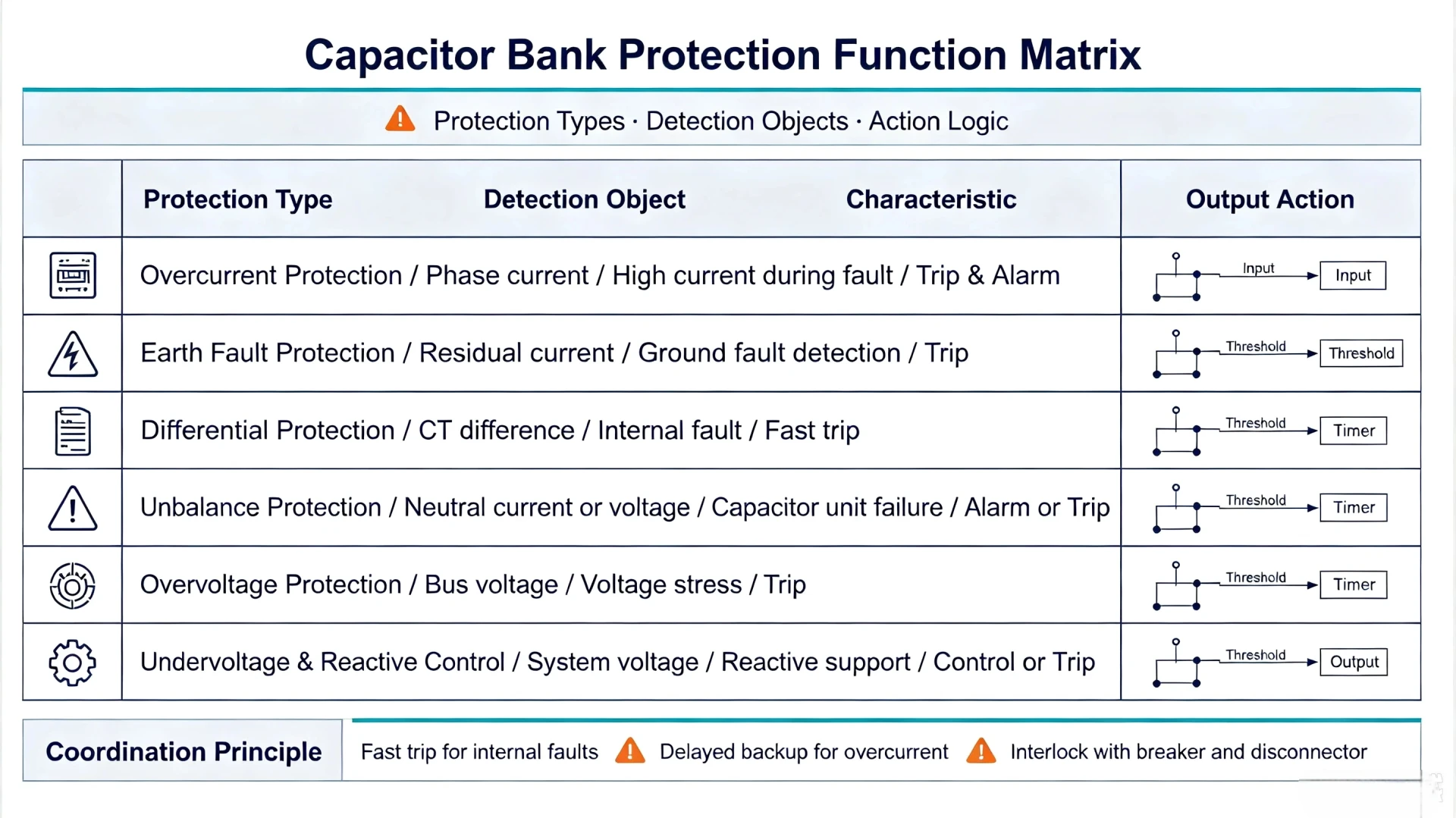
Capacitor Bank Protection: Protection Methods, Relays and Applications
Introduction
Capacitor bank protection is designed to detect internal capacitor degradation, unit failure, fuse blowing, system voltage anomalies, and ground faults. It delivers timely alarm or trip actions to isolate faulty equipment and protect the remaining healthy capacitor units.
This guide covers the core principles, mainstream protection methods, key protection devices, standard protection schemes, and relay selection criteria for capacitor banks. We focus on six essential protection functions: unbalance protection, overcurrent protection, earth-fault protection, overvoltage protection, undervoltage protection, and overload protection. We also explain how to configure a complete capacitor bank protection system and select qualified protection relays for different project scenarios.
Why Does a Capacitor Bank Need Protection?
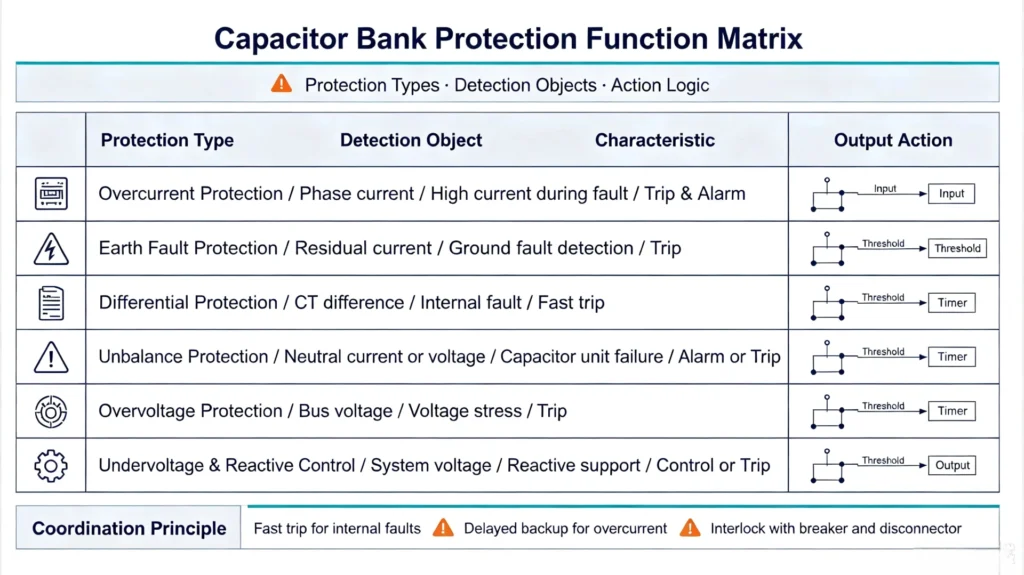
Common Capacitor Bank Faults and Abnormal Conditions
Capacitor bank faults are divided into internal component faults and external system abnormal conditions, which are the core targets of dedicated protection:
- Failed capacitor elements: Internal insulation aging or breakdown causes partial capacitance loss, triggering subtle current and voltage unbalance.
- Failed capacitor units: Complete failure of individual capacitor units leads to obvious parameter deviation of the entire bank.
- Blown capacitor fuses: Fuse actuation caused by local faults changes the series-parallel structure of the capacitor bank.
- Short circuits: Phase-to-phase or internal short-circuit faults generate huge transient fault currents.
- Ground faults: Insulation damage causes capacitor bank grounding faults, threatening system safety.
- Overcurrent: Sustained excessive operating current caused by system fluctuations or equipment anomalies.
- Overvoltage: Long-term system overvoltage accelerates capacitor insulation aging and breakdown.
- System voltage unbalance: Three-phase voltage asymmetry causes uneven stress on capacitor units.
- Switching disturbances: Frequent switching operations produce transient surge voltage and current impact.
Risks of Inadequate Capacitor Bank Protection
The biggest hidden danger of unprotected or improperly protected capacitor banks is cascading failure, a typical progressive fault in capacitor bank operation:
When individual capacitor elements or units fail, the overall capacitance of the bank changes, resulting in three-phase current and voltage unbalance. The remaining healthy capacitor units will bear higher voltage and current stress than rated values. Long-term over-stress accelerates insulation aging and secondary failure of adjacent units. Without timely alarm or tripping, minor local faults will gradually expand, causing large-scale damage to the capacitor bank, system voltage collapse, and unplanned power outage losses.
What Are the Main Types of Capacitor Bank Protection?
According to IEC TS 60871-3 and IEEE 18 industry standards, mainstream capacitor bank protection functions cover internal unit failure detection and external system fault protection. The core protection functions are summarized in the table below:
| Protection Function | What It Detects | Main Purpose |
|---|---|---|
| Unbalance Protection | Internal capacitor element/unit failure, three-phase parameter unbalance, blown fuses | Identify early capacitor degradation and local faults to prevent cascading failure |
| Overcurrent Protection | Excessive transient and sustained current caused by short circuits and severe faults | Quickly clear severe short-circuit faults to avoid equipment burnout |
| Earth-Fault Protection | Phase-to-ground insulation breakdown and grounding faults | Isolate grounding faults and prevent system grounding accidents |
| Overvoltage Protection | System overvoltage exceeding capacitor withstand rating | Protect capacitor insulation from aging and breakdown caused by overvoltage |
| Undervoltage Protection | System low voltage and abnormal power supply state | Prevent abnormal reactive power output and equipment misoperation |
| Overload Protection | Sustained overload operating current of the capacitor bank | Avoid long-term overload operation damaging capacitor units |
Capacitor Bank Unbalance Protection
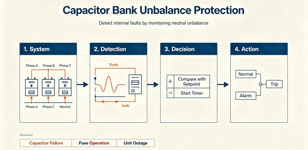
Unbalance protection is the most critical dedicated protection for capacitor banks, which solves the problem that minor internal capacitor failures cannot be detected by conventional overcurrent protection.
What Causes Capacitor Bank Unbalance?
Three-phase unbalance of capacitor banks is mainly caused by internal equipment anomalies, including damage of individual capacitor elements, failure of single capacitor units, blown internal/external fuses, and parameter deviation caused by long-term aging of partial units. System three-phase voltage unbalance will also aggravate capacitor bank operating unbalance.
How Is Unbalance Detected?
The protection relay monitors real-time three-phase current or voltage amplitude deviation of the capacitor bank. When the unbalance degree exceeds the preset threshold, the relay will trigger an alarm or trip command according to the fault severity, realizing early warning and fault isolation.
Current-Based vs Voltage-Based Unbalance Protection
Current-based unbalance protection collects three-phase operating current signals through CTs, suitable for most star and delta capacitor bank configurations, with high detection sensitivity for local unit failures. Voltage-based unbalance protection relies on VT sampling voltage signals, more applicable for ungrounded capacitor banks with obvious neutral point voltage displacement characteristics.
For a detailed explanation of detection methods, schemes and setting guidelines, see our guide to Capacitor Bank Unbalance Protection.
Capacitor Bank Overcurrent Protection
Overcurrent protection is the basic fault protection for capacitor banks, mainly used to deal with severe sudden short-circuit faults in the system or equipment.
Causes of Capacitor Bank Overcurrent
Common overcurrent scenarios include phase-to-phase short circuits of capacitor banks, internal short-circuit of capacitor units, short-circuit faults caused by insulation breakdown, and transient inrush current during capacitor switching.
Overcurrent Protection vs Unbalance Protection
Many project engineers confuse the application scenarios of overcurrent protection and unbalance protection. The core differences are clearly compared below:
| Item | Overcurrent Protection | Unbalance Protection |
|---|---|---|
| Main Target | High sudden fault current | Internal capacitor subtle abnormality and aging failure |
| Typical Fault | Phase-to-phase short circuit, severe grounding short circuit | Failed capacitor element/unit, blown fuse, parameter unbalance |
| Detection Method | Phase current / residual current sampling | Unbalance current / unbalance voltage calculation |
| Protection Objective | Fast fault clearing to prevent sudden equipment damage | Early detection of capacitor deterioration to avoid cascading failure |
For more professional setting and coordination rules for overcurrent protection, view our in-depth article: Capacitor Bank Overcurrent Protection Guide.
What Capacitor Protection Devices Are Used?
A complete capacitor bank protection system is a coordinated combination of multiple devices, rather than a single protection relay working independently. The core supporting devices include:
Capacitor Fuses
Including unit fuses and line fuses (compliant with IEC 60549:2013). Unit fuses isolate faulty single capacitor units to ensure the continuous operation of the whole bank; line fuses provide primary short-circuit protection for the entire capacitor bank.
Current Transformers (CT)
Collect three-phase operating current and residual current signals, providing accurate sampling data for overcurrent, unbalance and earth-fault protection.
Voltage Transformers (VT)
Sample bus voltage and capacitor bank terminal voltage, supporting overvoltage, undervoltage and voltage-based unbalance protection functions.
Protection Relays
The core control and protection unit of the system, integrating signal acquisition, logic judgment, alarm/trip output, and data monitoring functions.
Circuit Breakers
Execute fault isolation actions, cut off the capacitor bank from the power system after receiving the relay trip command, and bear normal switching operations.
Discharge and Monitoring Components
Discharge resistors or discharge coils eliminate residual voltage after capacitor bank shutdown; temperature and vibration monitoring components assist in real-time status diagnosis.
Capacitor Bank Protection Scheme
The standard protection workflow of industrial and utility capacitor banks follows a closed-loop detection and execution logic, with the core process as follows:
Capacitor Bank → CT/VT/Unbalance Detection → Protection Relay Logic Judgment → Alarm/Trip Command → Circuit Breaker Action → Fault Isolation & System Recovery
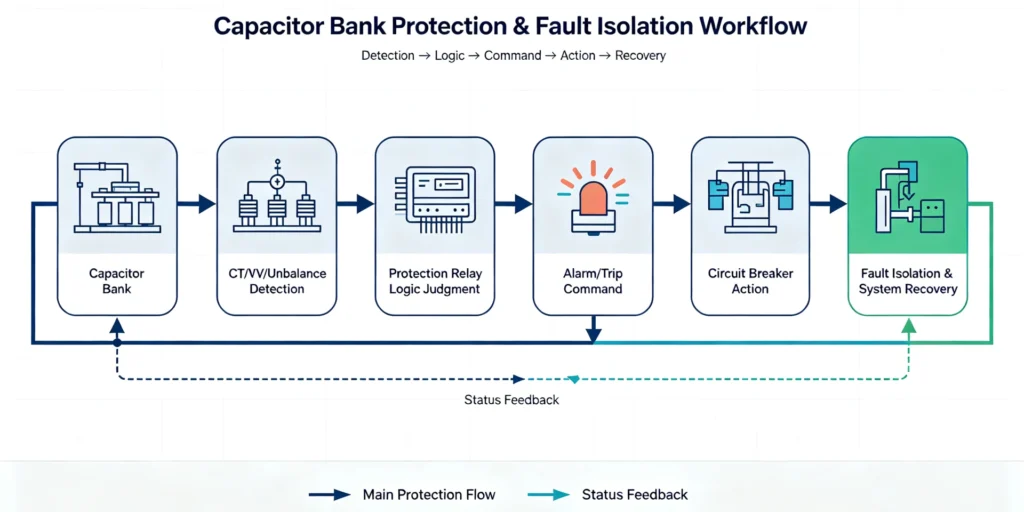
Protection Against Internal Capacitor Faults
Mainly covered by unbalance protection, matched with unit fuses. It targets element failure, unit damage and fuse blowing, realizing early warning and graded tripping to avoid fault expansion.
Protection Against External System Faults
Covered by overcurrent, earth-fault, overvoltage and undervoltage protection. It responds to power system short circuits, grounding faults and voltage anomalies to protect the capacitor bank from external impact damage.
Alarm and Trip Functions
For slow-developing minor unbalance faults, the relay outputs alarm signals to remind on-site maintenance; for severe short circuits, overvoltage and large-amplitude unbalance faults, the relay triggers immediate tripping to isolate faulty equipment.
How to Select Protection for a Capacitor Bank?
EPC contractors and project owners need to select and configure protection schemes based on actual project conditions. The key selection criteria are as follows:
Consider the Capacitor Bank Configuration
Different structures match different protection logics: single-star, double-star, and H-bridge configurations have different unbalance detection sensitivities; grounded and ungrounded banks require differentiated earth-fault and voltage unbalance protection settings.
Check Rated Voltage and Current
Match protection threshold parameters according to the capacitor bank’s rated voltage, rated current and withstand capacity to avoid malfunction or refusal to operate.
Determine Required Protection Functions
Low-voltage small-capacity banks can adopt simplified protection; medium and high-voltage large-capacity capacitor banks must fully configure unbalance, overcurrent, earth-fault, overvoltage and undervoltage protection.
Consider CT and VT Requirements
Select CT/VT transformation ratios and accuracy levels matching the protection scheme to ensure sampling accuracy and protection reliability.
Check Protection and Breaker Coordination
Optimize the action time and threshold of relays, fuses and circuit breakers to form a graded protection coordination system and avoid protection mismatch.
Consider Communication and Monitoring Requirements
For intelligent substation and remote monitoring projects, select relays with standard communication protocols to support real-time data upload and remote fault diagnosis.
Capacitor Bank Protection Relay: When Is It Required?
Traditional discrete protection devices have complex wiring, poor coordination and difficult maintenance. Integrated capacitor bank protection relays have become the mainstream solution for modern capacitor bank projects, with obvious application advantages:
- Integrate all core protection functions in one device, eliminating the need for multiple discrete relays
- Support high-precision electrical parameter measurement and real-time status monitoring
- Flexible alarm and trip logic configuration, adapting to various bank configurations
- Perfect protection coordination performance, matching fuses and breakers efficiently
- Simplify cabinet wiring and reduce on-site panel complexity
- Support multiple industrial communication protocols for intelligent system docking
CTA: Looking for a reliable capacitor bank protection relay for your industrial or utility project? Our ASC-441H Capacitor Bank Protection Relay integrates full protection functions, high-precision sampling and stable communication, fully compliant with IEC and IEEE industry standards. View ASC-441H Product Page
Frequently Asked Questions
1. What is capacitor bank protection?
Capacitor bank protection is a set of dedicated electrical protection schemes and devices, used to detect internal capacitor failures and external system anomalies, and execute alarm or trip actions to ensure the safe and stable operation of shunt capacitor banks.
2. What protection is required for a capacitor bank?
Standard mandatory protection functions include unbalance protection, overcurrent protection, earth-fault protection, overvoltage protection and undervoltage protection. Overload protection is configured according to project load characteristics.
3. What is capacitor bank unbalance protection?
It is a dedicated protection for internal faults of capacitor banks. It judges unit failure or fuse blowing by monitoring three-phase current/voltage unbalance, realizing early fault warning and preventing cascading failure.
4. What is the difference between capacitor bank overcurrent and unbalance protection?
Overcurrent protection copes with severe sudden short-circuit faults with fast tripping; unbalance protection detects subtle internal aging and local failures for early warning, covering blind spots of overcurrent protection.
5. What devices are used to protect capacitor banks?
The complete system includes capacitor fuses, CTs, VTs, integrated protection relays, circuit breakers and discharge monitoring components, realizing coordinated protection from sampling, judgment to execution.
Reference & Technical Sources
- IEC TS 60871-3:2015, Shunt capacitors for AC power systems above 1000V – Part 3: Protection of shunt capacitors and shunt capacitor banks
- IEC 60549:2013, High-voltage fuses for the external protection of shunt capacitors
- IEEE Standard 18, IEEE Standard for Shunt Power Capacitors
- IEEE C37.012-2022, IEEE Guide for Capacitive Current Switching for AC High-Voltage Circuit Breakers



About Author

Hello, I'm Leno Zhang. I have 15 years of experience in the power relay protection industry with extensive pre-sales and after-sales project experience. Our company specializes in various complete sets of relay protection and automation equipment. I can assist customers in solving all practical on-site project challenges and provide optimal integrated solutions.
Tell Us Your Requirement
High Quality
Stable performance, reliable design, ensuring safe operation for power system protection and grid stability.
Fast Delivery
Timely delivery to support your urgent orders and project schedules efficiently and professionally at any time.
Best Warranty
Professional Warranty: Reliable after-sales support for stable relay protection and long-term customer satisfaction.