

-
Leon Zhang sales consultant
-
Email: zxl635973785@gmail.com
-
Phone/WhatsApp: +86 13655813266
Bus Differential Protection: Working Principle, Schemes and Testing
Bus differential protection is the fastest way to clear an internal busbar fault before it spreads to the whole switchboard.
Written by Leon Zhang, Protection Application Engineer · Technical review by Li Ming, Electrical Engineer · Last reviewed September 2026
What Is Bus Differential Protection?
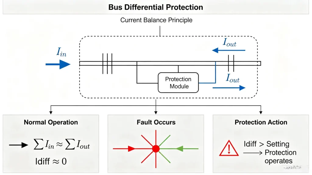
Bus differential protection is a high-speed scheme that detects busbar faults by comparing currents entering and leaving the bus. Based on Kirchhoff’s Current Law, the sum of all currents must equal zero under normal conditions. An internal fault generates a differential current that triggers the protection.
It protects the busbar, the critical node connecting feeders, transformers and generators. Bus faults can cause widespread outages and equipment damage; this protection clears faults within milliseconds to maintain system stability.
The ANSI function code is 87B, where “B” denotes busbar applications. The 87B scheme delivers high-speed, sensitive fault detection with built-in security against CT saturation and external faults.
How Does Bus Differential Protection Work?
Current Balance Principle
The scheme rests on Kirchhoff’s Current Law. Under normal operation, the current entering the bus equals the current leaving it:
Σ Iin ≈ Σ Iout → Idiff ≈ 0
When a fault occurs within the protection zone, the current balance is disrupted and a differential current is generated:
Idiff > Setting → Protection operates
Internal Bus Fault
When a short circuit occurs on the bus or connected equipment, all CTs within the zone detect the fault current, but the current does not exit through the feeders. The differential current exceeds the setting, and the relay immediately trips all connected breakers to isolate the fault.
External Fault and CT Saturation
During external faults, the current balance remains intact and the relay should not operate. However, in practice, high external fault currents may cause CT saturation, distorting the secondary current and creating a false differential current that could lead to mal-operation.
To prevent this, the 87B relay employs a restraint (bias) characteristic. It compares the differential current against the through-current: the higher the through-current, the higher the restraint threshold. The relay operates only when the differential current exceeds the restraint level. That keeps it stable during external faults and CT saturation while staying sensitive to true internal faults.
87B Busbar Protection Relay: Function and Role
ANSI 87B Function
The ANSI device number 87B designates the busbar differential function, and an 87B busbar protection relay is what implements it. The “87” prefix covers differential protection, while the “B” suffix specifically applies to busbar applications. An 87B relay monitors all currents entering and leaving a busbar zone, calculates differential current, and issues trip commands when internal faults are detected.
What Does an 87B Relay Protect?
- Busbars – main and transfer buses
- Switchgear bus sections – individual sections within a switchgear assembly
- Substation bus zones – defined protection zones within a substation
87B Relay vs Other 87 Protection Functions
| ANSI Code | Protection Function | Protected Asset |
|---|---|---|
| 87B | Busbar differential function | Busbars |
| 87T | Transformer Differential Protection | Power transformers |
| 87M | Motor Differential Protection | Large motors |
| 87G | Generator Differential Protection | Generators |
| 87L | Line Differential Protection | Transmission lines |
All 87-series functions operate on the differential current principle, but each is optimized for its specific asset. The 87B relay uniquely handles multiple current sources, rapidly changing bus configurations, and high bus fault current levels.
Bus Differential Schemes: Single, Double and Sectionalized
Single Busbar Differential Protection
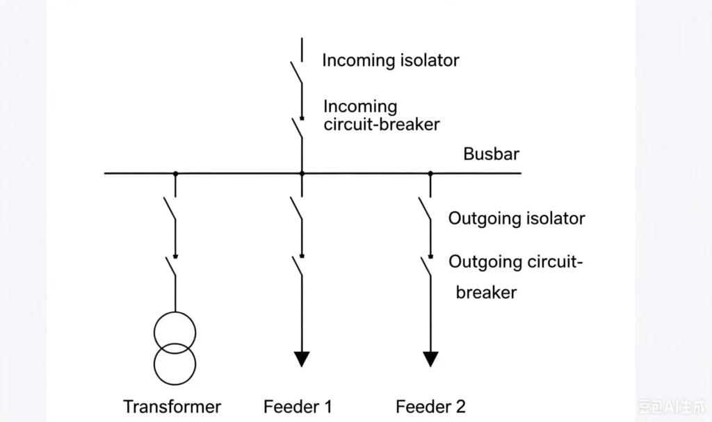
All feeders connect to a common bus, and the relay monitors every current as one zone. Of the four bus differential schemes this is the simplest. Any internal fault trips all breakers connected to the bus, completely isolating the fault.
Key features: Simple configuration, single zone, cost-effective for smaller substations and industrial facilities. However, a bus fault results in complete feeder outage.
Double Busbar Differential Protection
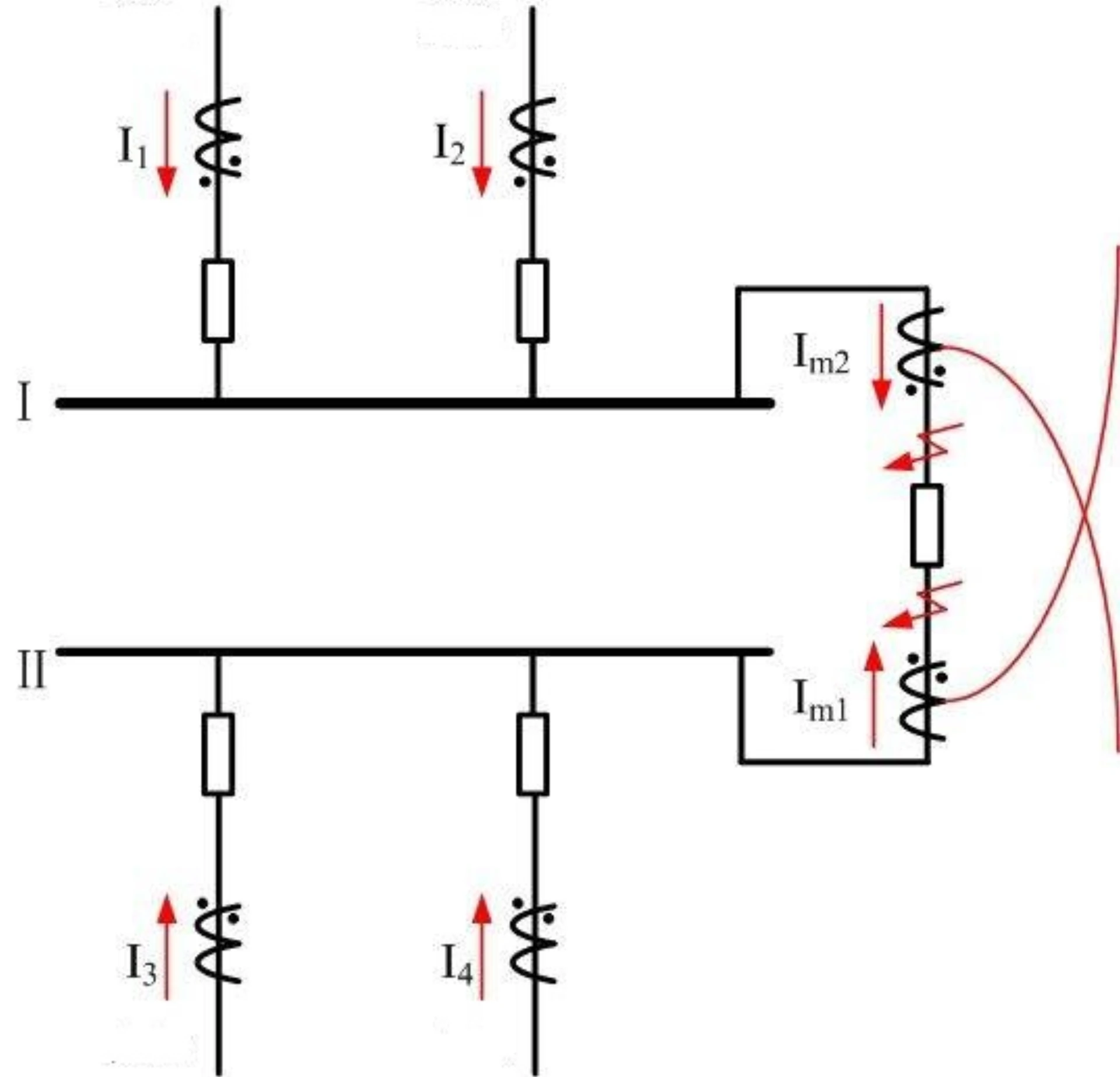
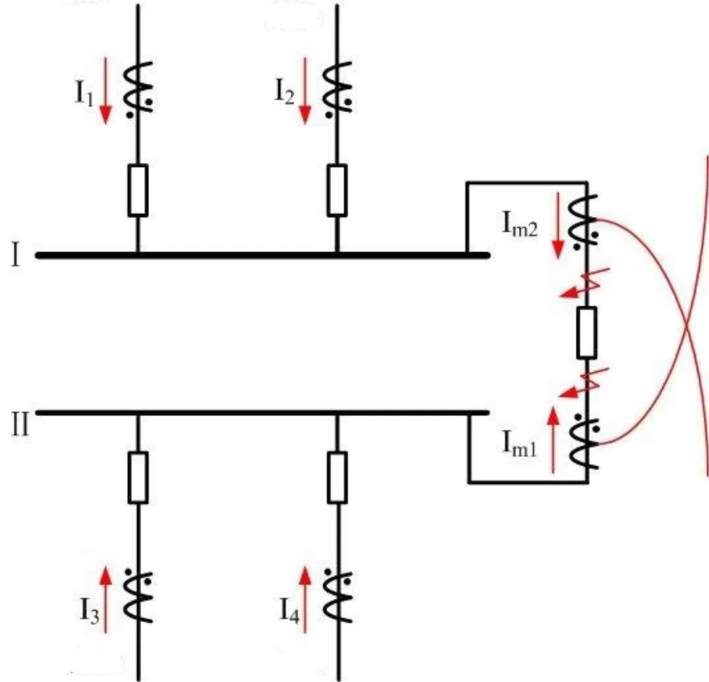
Double bus configurations provide redundancy and operational flexibility. The 87B relay implements large-difference (whole system) and small-difference (per bus section) functions. During switching, the relay automatically detects isolator position changes and adjusts zones without protection deactivation.
Key features: Two independent bus sections, fault detection + fault location, automatic mode adaptation.
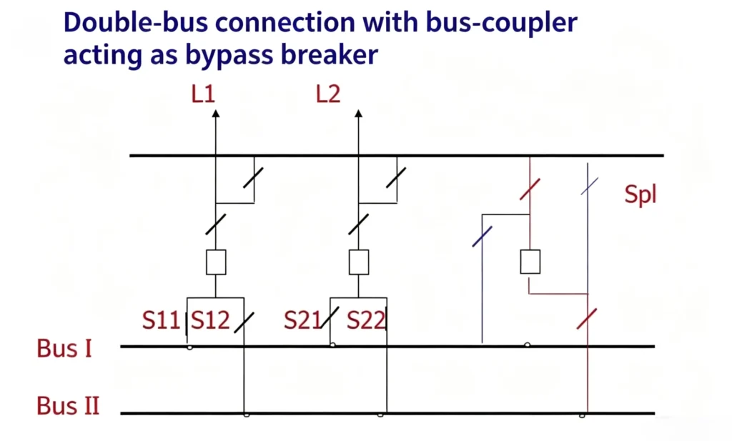
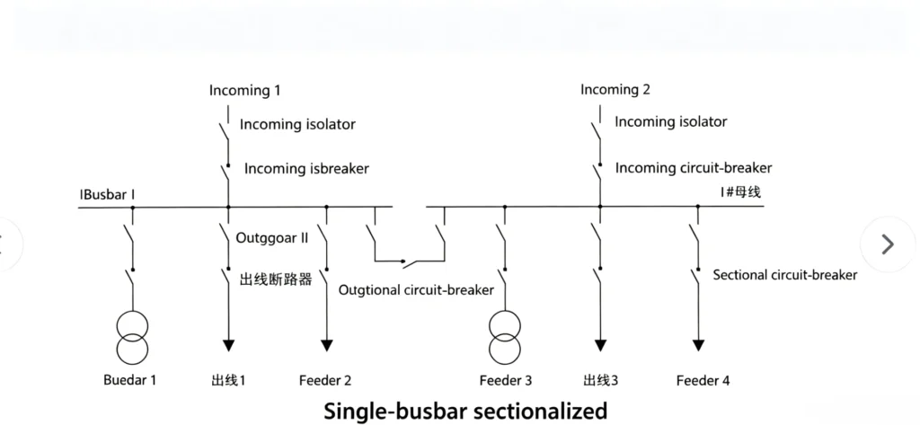
Sectionalized Busbar Protection
The bus is divided into sections connected by coupler breakers. Each section has its own differential zone. A fault in one section trips only that section, while healthy sections remain in service, so the outage stays inside that section.
Key features: Independent zones per section, fault isolation limited to affected section, improved supply continuity.
Main and Transfer Bus Protection
Main bus handles normal operation; transfer bus allows maintenance bypass. The 87B relay dynamically updates differential zones based on isolator and breaker positions during feeder transfers, ensuring correct operation regardless of switching state.
Key features: Dual-bus protection with transfer capability, dynamic zone reconfiguration, secure operation during switching.
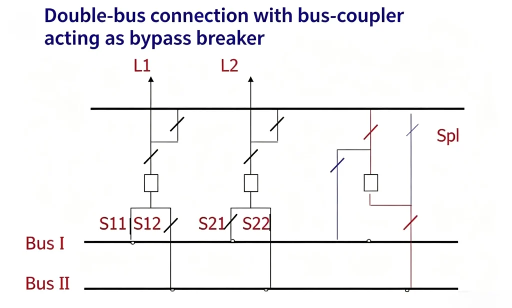
Busbar Protection Zones
What Is a Bus Protection Zone?
A bus protection zone is a defined portion of a busbar system protected as a single unit by the 87B relay. Each zone has its own CT inputs and differential logic. A fault inside a zone trips all breakers connected to that zone; a fault outside keeps the relay stable.
Main Protection Zone
The main zone covers the primary busbar section and all connected feeders. The 87B relay calculates differential current for each main zone using CT currents from all feeders in that zone. In double bus configurations, the relay tracks isolator positions and updates zone membership automatically.
Check Zone
The check zone is a supervisory element covering a larger area, typically the entire double bus system. It verifies that a fault is truly internal before allowing a trip. If CT saturation creates a false differential current in a main zone during an external fault, the check zone (seeing the fault as external) blocks the trip. This prevents mal-operation due to CT saturation or incorrect zone selection.
Dead Zone
A dead zone is the portion of busbar between a circuit breaker and a CT, where a fault may not be detected by main differential protection. The 87B relay provides dedicated dead zone logic using breaker status and additional CT inputs to detect faults in these blind spots and trip the appropriate breakers.
Zone Summary
| Zone Type | Function | Coverage |
|---|---|---|
| Main Zone | Primary differential protection | Individual bus section |
| Check Zone | Supervisory security | Entire busbar system |
| Dead Zone | Fault detection in blind spots | Between CT and breaker |
CT Requirements for a Busbar Zone
CTs are the most critical external components in a busbar zone scheme. The 87B relay’s performance, tripping on internal faults and staying stable on external faults, depends directly on CT selection and installation.
CT Ratio Matching
All CTs on connected feeders should have the same ratio. Modern numerical relays can compensate for mixed ratios through software, but verify that the relay supports ratio correction and CT ratings are not exceeded when using partial windings.
CT Polarity
All CTs must be connected with consistent polarity, typically with polarity marks facing the bus. A single reversed CT produces differential current under load that may exceed the pickup setting, causing false trips. Commissioning with load current quickly identifies wiring errors.
CT Accuracy
Select CTs with adequate accuracy class to ensure reliable measurement across the full fault current range. Numerical relays can indicate measured values during commissioning to verify CT performance.
CT Saturation
CT saturation is the most important factor affecting protection security. During external faults, saturated CTs distort secondary currents, creating false differential current that may cause mal-operation.
Key considerations:
- Restraining characteristics and saturation detectors maintain stability
- Knee-point voltage should be ≥2× relay voltage setting
- Residual magnetism can reduce linear operation by up to 5×, so assume remanence up to 80% of saturation level
Linear operation limit:
Imax = Vsat / Rs
where Rs is total burden resistance.
CT Secondary Wiring
Wiring errors, loose connections, or open circuits compromise protection. Modern 87B relays include CT broken-line detection to monitor circuit continuity and block protection when disconnection is detected.
CT Burden and Lead Resistance
Total burden includes CT secondary resistance, lead resistance (both ways), and relay input burden:
Rs = 2Rlead + RCTsec + Rrelay
High lead resistance increases burden and reduces CT linear operation capability. Use the minimum linear operation limit across all CTs as the basis for differential characteristic settings.
CT Parameter Summary
| CT Parameter | Why It Matters |
|---|---|
| CT Ratio | Current matching for correct differential calculation |
| Polarity | Reverse connection causes false trips |
| Accuracy Class | Reliable measurement across fault range |
| Knee-Point Voltage | Determines saturation performance |
| Secondary Resistance | Affects CT saturation under external faults |
| Burden / Lead Resistance | Reduces CT linear operation capability |
| Remanence | Residual flux can severely limit linear operation |
High-Impedance vs Low-Impedance Bus Differential Protection
| Feature | High-Impedance | Low-Impedance |
|---|---|---|
| Protection principle | Voltage-based | Current-based |
| CT requirements | Same ratio and characteristics | Different ratios accepted |
| Mixed CT ratios | Limited | Better suited |
| Complex busbar schemes | Fixed, less flexible | Dynamic, more flexible |
| CT saturation immunity | Excellent | Algorithm-dependent |
| Bus configuration | Fixed | Dynamic |
| Application | Traditional, simple schemes | Modern numerical substations |
The choice follows the CTs you already have. Where every feeder CT shares a ratio and class, a high-impedance scheme is hard to beat on saturation immunity and needs no settings. Where ratios are mixed or the bus reconfigures, the low-impedance scheme is the only one that can be made to work.
87B Settings: What Each One Does
This section provides a conceptual overview of key settings. Actual settings must be determined based on CT parameters, bus configuration, fault levels, relay model and protection philosophy. Values vary substantially between relays and should be calculated by protection engineers during design.
Differential Pickup
Defines the minimum differential current required for operation. Set high enough to avoid mal-operation during normal operation, CT errors, and inrush, yet low enough to detect high-resistance internal faults.
Restraint / Bias Slope
Ensures relay stability during external faults with CT saturation. The slope defines how much the differential current increases as through-current rises. Typically 2–4 slopes. Higher slopes give more security on external faults, lower slopes give more sensitivity on internal faults.
High-Set Differential Element
An instantaneous unrestrained element for high-magnitude internal faults, providing ultra-fast tripping when the biased element may be delayed. Set above the maximum expected through-current.
CT Saturation Detection
Modern relays use waveform analysis (harmonics or sudden changes) to detect CT saturation. During saturation, restraint is temporarily increased to prevent mal-operation without delaying tripping for true internal faults.
Check Zone Settings
Check zone sensitivity is typically set equal to or greater than the main zone, ensuring that internal faults are confirmed by the check zone before tripping, which adds a second layer of security.
Bus Zone Selection
For multi-zone configurations, zone definitions, isolator mapping, and CT assignments must be configured. Zone definitions must match physical busbar arrangement and switching logic must be validated during commissioning.
Setting Ranges Are Relay-Specific
The above are conceptual guidelines only. Actual settings vary by relay model, so always refer to the specific relay’s technical manual for detailed setting procedures and ranges.
Bus Differential Testing: Commissioning and Injection Tests
Bus differential testing exists to answer two questions before the bus is energised: does the relay trip for an internal fault, and does it stay stable for an external one. The following test sequence represents standard industry practice for commissioning and periodic maintenance.
1. Visual Inspection
Before energizing any circuits, perform a thorough visual inspection of all hardware.
Checklist:
- Relay physical condition: no damage, loose components, or signs of overheating
- CT secondary wiring: terminals tight, no open circuits, correct wire labeling
- CT grounding: each CT circuit grounded at one point only
- Communications and I/O wiring: Ethernet, RS-485, and binary I/O connections verified
- Power supply connections: correct voltage and polarity
2. CT Circuit Check
Verify that all CT circuits are complete and correctly wired.
Procedure:
- Measure DC resistance of each CT secondary circuit to ensure continuity
- Check that no CT circuits are left open
- Verify that CT secondary wiring matches the scheme diagram
- Record measured resistance values for future reference
3. CT Polarity Test
CT polarity must be verified before applying load. This is arguably the most critical pre-energization test.
Procedure:
- Apply a DC voltage to the primary circuit and observe secondary polarity
- Alternatively, inject a small AC current and measure phase relationships
- Confirm that all CTs are connected with consistent polarity (polarity marks facing the bus)
- Check phase identification: A→A, B→B, C→C throughout the circuit
4. Secondary Injection Test
Inject currents directly into the relay’s analog inputs to verify correct hardware operation and scaling.
Procedure:
- Inject known current values (e.g., 1A, 5A) into each analog input channel
- Verify that relay displays the correct measured values
- Check phase angle accuracy using injection test set
- Confirm that all channels are correctly assigned to their respective zones
5. Differential Protection Pickup Test
Verify that the relay operates at the correct differential pickup setting.
Procedure:
- Inject balanced currents into all CT inputs; the relay should not operate
- Gradually increase current in one phase until the relay operates
- Record the pickup current value; compare against setting
- Repeat for all phases and all zones
- Verify that check zone operates as expected
6. External Fault Stability Test
This test confirms that the relay remains stable during high through-current conditions, even with CT saturation.
Procedure:
- Inject high through-currents (up to 20× rating) through all feeders
- For CT saturation simulation: inject currents at angles causing saturation-like waveforms
- Verify that the relay does not issue a trip command
- Check that restraint current and differential current are correctly calculated
- Confirm that saturation detection logic operates as designed
7. Internal Fault Trip Test
Verify that the relay trips correctly for simulated internal faults.
Procedure:
- Inject currents representing an internal bus fault (e.g., one feeder high current, others zero)
- Verify that the differential current exceeds the pickup setting
- Confirm that the relay issues trip command within specified time (≤25ms)
- Check that the correct zone is identified and associated breakers are selected
- Repeat for multiple fault locations across all zones
8. Trip Logic and Breaker Test
Verify that trip commands are correctly routed to the intended circuit breakers.
Procedure:
- Simulate internal faults and confirm that trip outputs are activated
- Verify that trip contacts close and open within specified time
- Test breaker failure protection (50BF) logic:
- Simulate a fault with breaker failure condition
- Verify Stage 1 retrip and Stage 2 GOOSE/remote trip activation
- Confirm correct breaker fail/retrip logic for each zone
9. Event Record Verification
Modern 87B relays record event data for post-fault analysis. Verify that recording functions are operational.
Procedure:
- Generate test events (manual trip, fault simulation)
- Download event records and fault reports from the relay
- Verify that records contain accurate time stamps, current values, and zone information
- Confirm that event storage capacity and retrieval functions are working
- Check time synchronization (SNTP, IRIG-B, GPS) is accurate in event logs
Test Summary Checklist
| Test Step | Purpose | Status |
|---|---|---|
| Visual Inspection | Verify hardware and wiring integrity | ☐ |
| CT Circuit Check | Ensure continuity and correct wiring | ☐ |
| CT Polarity Test | Verify consistent CT polarity | ☐ |
| Secondary Injection | Verify relay measurement accuracy | ☐ |
| Pickup Test | Confirm differential pickup setting | ☐ |
| External Fault Stability | Verify stability under through-faults | ☐ |
| Internal Fault Trip | Verify correct tripping for internal faults | ☐ |
| Trip Logic / Breaker | Confirm trip routing and 50BF logic | ☐ |
| Event Record Verification | Ensure data recording is functional | ☐ |
Commissioning Before Energisation
Commissioning is a system-level verification process performed before primary energization to confirm that the 87B relay and associated systems are ready for service. It focuses on actual wiring, SCADA integration, and final operational readiness.
Pre-Commissioning
Wiring Verification
- Confirm all CT secondary circuits are complete and correctly terminated at relay terminals
- Verify binary inputs (breaker status, isolator positions) and trip output wiring
- Check power supply and communication cables (Ethernet, RS-485, fiber optic)
- Confirm CT grounding, with each circuit grounded at one point only
CT Polarity and Ratio
- Perform DC polarity test to confirm consistent CT polarity
- Verify CT ratios match relay configuration
- Confirm phase identification (A, B, C) is consistent throughout
Settings Verification
- Upload and verify setting file against the approved calculation sheet
- Confirm zone definitions match physical busbar configuration
- Verify isolator mapping for double bus and sectionalized configurations
- Check communication parameters (IP, MMS/GOOSE) and time synchronization (SNTP, IRIG-B, GPS)
Communication Verification
- Establish communication with SCADA via IEC 61850-MMS
- Verify data point mapping and updates
- Test GOOSE messaging for interlocking and remote trip
- Confirm SNTP time synchronization is accurate
Functional Commissioning
Using current injection to simulate fault conditions and verify relay response.
Internal Fault Simulation
- Apply currents representing internal bus faults for each zone
- Verify relay operates within ≤25ms and selects the correct zone
- Confirm check zone validates the trip decision
External Fault Stability
- Apply high through-fault currents to simulate external faults
- Verify relay remains stable and does not trip
- Confirm CT saturation detection logic operates correctly
Breaker Trip and Alarm
- Confirm trip outputs correctly activate associated breakers
- Test breaker failure protection (50BF), Stage 1 retrip and Stage 2 GOOSE remote trip
- Verify pickup, trip, and alarm signals are correctly generated
Blocking Logic
- Test external blocking inputs
- Verify relay blocks or unblocks protection as designed
- Confirm check zone blocking operates during external faults
Final Verification
Event Records and SOE
- Generate test events and download records
- Verify accurate time stamps, current values, and zone information
- Check SOE chronology of binary input/output changes
SCADA Signals
- Confirm all protection signals are correctly transmitted to SCADA (trip, zone, alarms, measured values)
- Verify display status matches actual conditions
- Test remote control functions (if applicable)
Trip Circuit
- Confirm trip coils are reliably energized during simulated trips
- Verify trip circuit supervision functions are operational
Protection Coordination
- Confirm 87B settings coordinate with upstream and downstream protection
- Verify grading meets system requirements
Commissioning Sign-Off Checklist
| Activity | Status | Remarks |
|---|---|---|
| Wiring Verification | ☐ | |
| CT Polarity / Ratio | ☐ | |
| Settings Verification | ☐ | |
| Communication Verification | ☐ | |
| Internal Fault Simulation | ☐ | |
| External Fault Stability | ☐ | |
| Breaker Trip / Alarm | ☐ | |
| Blocking Logic | ☐ | |
| Event Records / SOE | ☐ | |
| SCADA Signals | ☐ | |
| Trip Circuit | ☐ | |
| Coordination Verification | ☐ |
How to Select an 87B Relay
Selecting the right relay requires evaluating substation requirements, existing equipment, and future expansion plans. The following checklist provides a structured selection approach.
Selection Checklist
| Selection Factor | What to Check |
|---|---|
| Busbar Configuration | Single bus, double bus, sectionalized, and so on. The relay must support your topology |
| CT Configuration | Ratio, accuracy, knee-point voltage, saturation characteristics and secondary burden must all be compatible with the relay input requirements |
| Protection Zones | Main zones, check zone and dead zone: ensure the relay supports the required zone architecture |
| Communication Protocol | IEC 61850, Modbus, DNP3.0: match the substation automation standard |
| Communication Ports | Ethernet port count, RS-485, CAN, fiber optic: confirm the physical interfaces meet integration needs |
| Breaker Failure | Required? If yes, confirm relay includes integrated 50BF |
| Event Recording | SOE and fault waveform capture, both essential for fault analysis |
| Engineering Interface | Local HMI, PC software, remote access: evaluate commissioning convenience |
| Expansion Capability | Provision for future bays and zone expansion, and avoid relays with fixed, non-upgradable capacity |
Additional Considerations
- System Voltage and Fault Level: Confirm relay rating suits system voltage and current input range can handle maximum fault current
- Relay Architecture: Digital over electromechanical; modular design for easy upgrades; firmware upgradeable for long-term support
- Commissioning and Maintenance: User-friendly software, built-in test routines, online testing capability
- Vendor Support: Technical support, documentation quality, training resources
- Cost and Value: Initial cost against lifecycle cost; modular relays offer better long-term value
No Single Relay Fits Every Substation
There is no “one-size-fits-all” relay. The optimal selection depends on specific substation requirements. Always engage with the manufacturer’s application engineering team to confirm the selected relay meets all technical and operational requirements.
87B Relay Applications
The 87B relay is used across every voltage level where losing a busbar would cost more than the switchgear around it, which in practice means HV and MV substations, power plants and large industrial intake substations.
| Application | Typical Voltage | Common Bus Configurations | Key Benefit |
|---|---|---|---|
| HV Substations | 110 kV | Double bus, bus tie | System stability |
| MV Substations | 6–35 kV | Single bus, sectionalized | Reliable fault clearing |
| Power Plants | 6–110 kV | Single, double, auxiliary | Generation protection |
| Industrial Substations | 6–35 kV | Single, sectionalized | Production continuity |
| Renewable Energy | 10–35 kV | Single, double | Generation retention |
| Utility Substations | 35–110 kV | Double, one-and-half | Network reliability |
| Switchgear Systems | 6–35 kV | Single, double | Space-saving protection |
87B Relay for Busbar Zones
For projects requiring numerical busbar differential protection, our 87B relay is built for numerical busbar schemes in medium- and high-voltage substations.
Conclusion
Bus differential protection remains the fastest way to clear an internal busbar fault. Choose 87B with a scheme matched to your CTs and zone layout, then prove it at commissioning.
Related Reading
- differential relay
- 87B bus differential protection relay
- protection relay testing and commissioning
- transformer differential protection
FAQ
Q1. What is bus differential protection?
Based on Kirchhoff’s Current Law, the phasor sum of currents entering and leaving the bus equals zero under normal conditions. An internal fault disrupts this balance, generating a differential current that triggers protection tripping.
Q2. What is ANSI 87B protection?
ANSI 87B is the function code for the busbar differential function. “87” designates differential protection, and “B” identifies busbar applications.
Q3. How does bus differential protection work?
The relay compares the operating current (differential current) against the restraining current (through-current). During external faults, differential current is small while restraining current is large, so the relay stays stable. On an internal fault the differential current exceeds the setting and the relay trips.
Q4. What causes false operation of bus differential protection?
The primary cause is CT saturation. High external fault currents saturate CTs, distorting secondary currents and creating false differential current. Other causes: reversed polarity, open CT circuits, and mismatched CT ratios.
Q5. What is the difference between high-impedance and low-impedance busbar protection?
A high-impedance scheme is voltage-based and needs every CT on the zone to share a ratio and class, which buys excellent saturation immunity and no settings to calculate. A low-impedance scheme is current-based, accepts mixed ratios and follows a changing bus, and its saturation performance depends on the algorithms in the relay.
The full row-by-row comparison is in the schemes section above.
Q6. What CT requirements are important for 87B protection?
- CT ratios should be consistent (low-impedance relays offer software compensation)
- Polarity must be consistent, with polarity marks facing the bus
- Knee-point voltage ≥ 2× stability voltage
- CT burdens should be balanced
Q7. How is bus differential protection tested?
- CT polarity test
- Differential pickup test
- Slope characteristic test
- External fault stability test
- CT saturation simulation test
Q8. Can an 87B relay protect multiple busbar sections?
Yes. Supports sectionalized bus, double bus (large-difference + small-difference), and configurations with bus tie/coupler. A single relay protects up to 8 bays; multiple relays can be cascaded to expand to 32 bays and 5 zones.
Technical References
| Source | What it covers | Type | Edition |
|---|---|---|---|
| IEC 60255-187-1 | Functional requirements for differential protection of motors, generators and transformers | Standard | 2021 |
| IEEE C37.110 | Guide for the application of current transformers used for protective relaying | Guide | 2023 |
| IEC 61869-2 | Instrument transformers – additional requirements for current transformers | Standard | 2012 |
| IEC 60255-1 | Measuring relays and protection equipment – common requirements | Standard | 2022 |
| ANSI/IEEE C37.2 | Device function numbers, acronyms and contact designations | Standard | 2022 |



About Author

Hello, I'm Leno Zhang. I have 15 years of experience in the power relay protection industry with extensive pre-sales and after-sales project experience. Our company specializes in various complete sets of relay protection and automation equipment. I can assist customers in solving all practical on-site project challenges and provide optimal integrated solutions.
Tell Us Your Requirement
High Quality
Stable performance, reliable design, ensuring safe operation for power system protection and grid stability.
Fast Delivery
Timely delivery to support your urgent orders and project schedules efficiently and professionally at any time.
Best Warranty
Professional Warranty: Reliable after-sales support for stable relay protection and long-term customer satisfaction.