

-
Leon Zhang sales consultant
-
Email: zxl635973785@gmail.com
-
Phone/WhatsApp: +86 13655813266
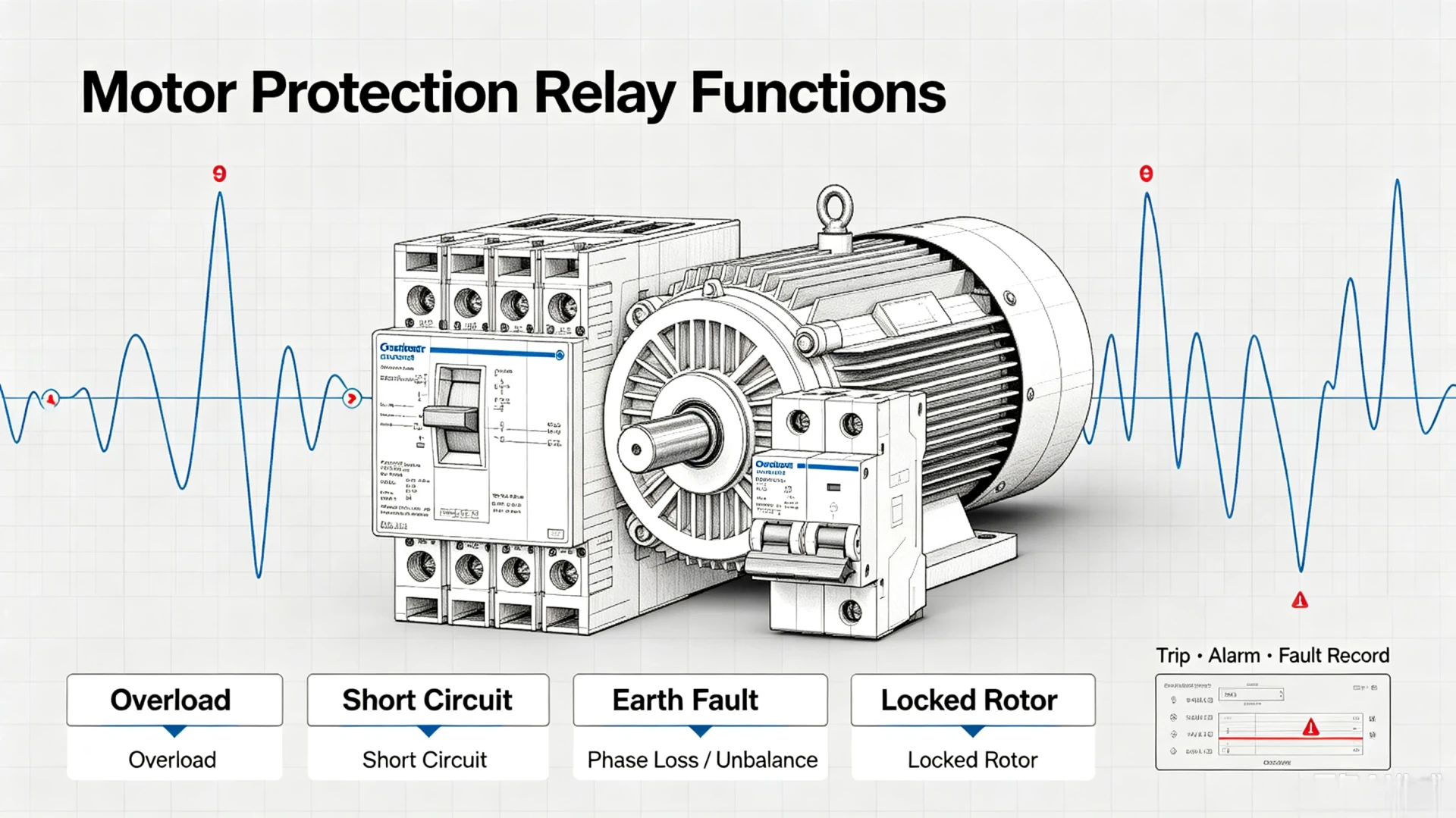
Motor Protection Relay Functions: ANSI 48, 49, 50, 51 and Beyond
Motor protection relay functions are the protection stages inside a motor protection relay that watch one motor and trip the starter before the winding is damaged. On most feeders that set is short: 49 thermal overload, 48 locked rotor, 50/51 short circuit, 50N/51N earth fault, 46 phase loss and unbalance, 47 phase sequence, 66 start limits, plus 27/59 voltage and RTD temperature sensing.
At a glance, these are the motor protection relay functions on a typical motor feeder, each one tied to an ANSI device number:
- 49: thermal overload, mirroring winding heating against the motor thermal capacity and tripping on accumulated heat.
- 48 / 51LR: locked rotor, timing out the starter when the motor never reaches full speed.
- 50 / 51: short circuit, split into instantaneous 50 and inverse-time 51 overcurrent.
- 50N / 51N: earth fault, picking up residual or zero-sequence current to earth.
- 46: negative sequence, catching a lost phase and uneven phase currents.
- 47: phase sequence, holding the starter out on reversed rotation.
- 66: starting frequency, capping the number of starts inside one set window.
- 27 / 59 / 37 / RTD: supply and temperature, covering undervoltage, overvoltage, undercurrent and direct winding temperature.
A circuit breaker only sees current magnitude, so it cannot separate a running overload from a healthy starting inrush. The relay adds a thermal model, locked-rotor timing and negative-sequence logic on top of the same CT signals, which is why the two are specified together on a motor feeder.
Everything below follows the ANSI/IEEE C37.2-2022 device numbering and the motor protection practice in IEEE 3004.8 and the IEC 60255 series. Plant teams fit these functions on pumps, fans, compressors and conveyors, where one unplanned stop costs more than the motor itself.
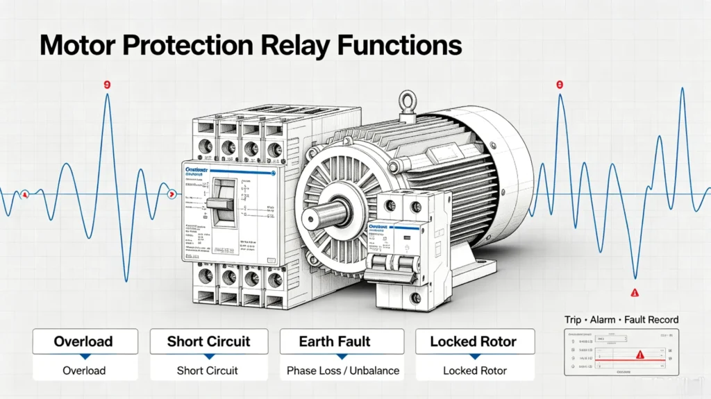
Each section below takes one function on its own: the fault it sees, the setting that starts the trip, and where it belongs on a low-voltage pump set or a medium-voltage drive. The layout is the same for one starter or a whole MCC row; only the current settings differ.
What Do Motor Protection Relay Functions Do?
The core working logic of a motor protection relay is real-time monitoring, intelligent judgment, and rapid fault response.
It continuously collects multiple operational parameters of the motor during startup and steady-state operation, compares real-time data with preset threshold values, and executes alarm or trip commands once abnormal conditions are identified.
The standard monitoring scope of industrial motor protection relays includes:
- Three-phase operating current and fault current
- Three-phase supply voltage and voltage deviation
- Power frequency and phase sequence status
- Motor startup time and acceleration characteristics
- Thermal load and winding temperature
- Ground fault residual current
- Real-time load operating status
Not every motor protection relay supports the full function set.
Availability depends on the relay model, motor voltage level (LV/MV), rated power, and on-site protection requirements. Basic relays only provide overload and overcurrent protection. Multi-functional industrial relays add full fault monitoring and system linkage, which is the mainstream configuration for modern industrial motor protection.
Main Motor Protection Relay Functions (ANSI Standard Overview)
All industrial motor protection functions follow unified ANSI/IEEE standard device numbers, enabling consistent technical communication and scheme configuration among global electrical engineers. These are the ANSI motor protection functions that a motor circuit actually uses: 49, 50/51, 50N/51N, 46, 27/59, 48, 37 and RTD. Motor protection functions explained below map each device number to the fault it clears, and the table summarizes core protection functions, corresponding standard codes, and protected fault types for quick engineering reference.
| Protection Function | ANSI Device No. | Protected Faults & Risks |
|---|---|---|
| Thermal Overload Protection | 49 | Motor overheating from long-term overload, insulation aging, and thermal damage |
| Overcurrent & Short-Circuit Protection | 50/51 | Instantaneous short-circuit current and long-term excessive operating current |
| Earth-Fault Protection | 50N/51N / 50G/51G | Winding insulation damage, cable leakage, and system ground faults |
| Phase Loss Protection | 46 | Single-phase open circuit, abnormal current imbalance, and motor overheating |
| Phase Sequence Protection | 46 | Reverse rotation caused by incorrect phase sequence during commissioning or wiring |
| Current Unbalance Protection | 46 | Negative-sequence current, rotor overheating, and reduced motor service life |
| Undervoltage Protection | 27 | Insufficient supply voltage, reduced torque, and startup failure |
| Overvoltage Protection | 59 | Excessive voltage stress and winding insulation breakdown |
| Locked-Rotor & Starting Protection | 48 | Rotor stalling, mechanical jams, and abnormal startup timeout |
| Undercurrent & Loss-of-Load Protection | 37 | Load loss, pump dry running, and broken transmission parts |
| Starting Frequency Limit | 66 | Winding overheating from too many start attempts inside one time window |
| Temperature Protection (RTD) | 49/RTD | Overheating of motor windings and bearings (direct temperature monitoring) |
Thermal Overload Protection (49): Core Motor Thermal Safety
Thermal overload protection is the most fundamental and widely used function of motor protection relays. It targets cumulative thermal damage from long-term abnormal operation. Start every 49 setting from the nameplate current.
How Thermal Overload Protection Works
Motors generate heat synchronously with operating current.
When the motor bears excessive mechanical load or runs under abnormal electrical conditions, the operating current rises continuously, leading to accumulated heat inside the winding. The relay calculates real-time thermal stress through a built-in thermal simulation model, tracks the motor’s heat accumulation and dissipation status, and triggers an alarm or trip once the thermal limit exceeds the rated threshold.
Why Overload Protection Matters on Every Motor
Most motor damage in industrial sites is caused by chronic overload rather than sudden faults.
Long-term minor overload will gradually age winding insulation, reduce motor efficiency, and eventually lead to short circuits or winding burnout. Different from instantaneous fault protection, 49 protection focuses on cumulative thermal damage, providing full-cycle protection for continuous motor operation.
Overload Protection vs Short-Circuit Protection
Engineers often confuse these two core functions; the core differences are clearly distinguished below. Sizing is a separate step, so the short-circuit protection relay page covers the current level and the breaker coordination:
| Protection Type | Typical Fault Condition | Response Characteristic |
|---|---|---|
| Thermal Overload (49) | Long-duration slight or moderate overcurrent, continuous overload | Time-dependent delayed trip, matching motor heat dissipation rules |
| Short-Circuit Protection (50/51) | Instantaneous huge fault current, metal short circuit | Ultra-fast instantaneous trip to avoid equipment burnout |
Overcurrent and Short-Circuit Protection (50/51)
Overcurrent and short-circuit protection is the first line of defense against sudden severe motor faults. It runs in two modes. One is instantaneous, the other inverse-time.
Instantaneous Overcurrent (50): Triggers an immediate trip when the fault current exceeds the preset instantaneous threshold, aiming at sudden short-circuit faults such as winding short circuits and cable breakdown, which can cause instantaneous high current and equipment burnout.
Time-Graded Overcurrent (51): Adopts inverse-time delay characteristics. The higher the overcurrent value, the shorter the action time. It is used for minor overcurrent faults and realizes protection coordination with upstream circuit breakers to ensure graded fault isolation and avoid full-system power failure.
This function is mandatory for all high-power industrial motors, effectively avoiding major equipment losses and electrical safety accidents caused by sudden short circuits.
Earth-Fault Protection (50N/51N): Insulation and System Safety
Ground faults are common hidden dangers in motor operation, mostly caused by winding insulation aging, cable sheath damage, damp on-site environment, or wiring errors. Zero-sequence current is the quantity to watch.
Working Principle
Under normal three-phase balanced operation, the vector sum of three-phase current is zero, with no residual current.
When a single-phase ground fault occurs, zero-sequence residual current is generated in the system. The relay monitors zero-sequence current in real time and judges ground fault levels to execute alarm or trip actions.
Application Value
Minor ground faults will not trigger immediate tripping but will continuously erode motor insulation; sustained faults will evolve into phase-to-phase short circuits and burn out windings. 50N/51N ground fault protection can capture early hidden faults, eliminate risks in advance, and protect motor insulation and power system safety, which is especially critical for humid, dusty, and harsh industrial environments.
Phase Loss and Current Unbalance Protection (46)
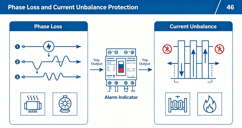
Three-phase asynchronous motors strictly rely on balanced three-phase power supply. Phase loss and current unbalance are frequent on-site faults. Both overheat the motor and shorten its life.
Phase Loss Protection
When one phase of the power supply is open due to fuse burnout, wiring looseness, or switch failure, the motor will continue to operate with two phases. This leads to a sharp increase in single-phase current, serious local overheating, and rapid insulation aging. The relay quickly identifies phase loss anomalies and cuts off the power supply to prevent motor burnout.
Current Unbalance Protection (Negative-Sequence Protection 46)
Unequal three-phase current will generate negative-sequence current inside the motor.
This current will produce reverse torque, cause rotor overheating, reduce operating efficiency, and shorten motor service life. The 46 protection function monitors negative-sequence current in real time and gives targeted protection for unbalanced power supply and load asymmetry scenarios.
Phase Sequence Protection
Phase sequence determines the rotation direction of three-phase motors. Wrong phase sequence during commissioning or grid switching reverses it. Fix it before the first run.
For core equipment such as pumps, fans, compressors, and conveyor belts, reverse rotation will cause process system disorder, equipment collision, and even project shutdown losses. The phase sequence protection function automatically identifies abnormal phase sequences and locks motor startup to avoid operational mistakes and equipment damage, which is a necessary protection function for new project commissioning and equipment overhaul.
Undervoltage and Overvoltage Protection (27/59)
Undervoltage Protection (27)
When the grid voltage drops abnormally, the motor’s output torque drops sharply.
To maintain normal load operation, the motor will automatically increase the operating current, resulting in overheating and startup failure. Long-term undervoltage operation will damage the motor and affect the stability of the entire production line, which is suitable for grid-fluctuating industrial parks and remote project sites.
Overvoltage Protection (59)
Instantaneous overvoltage caused by grid surge, lightning strike, or system switching will produce strong voltage stress on motor windings, break down insulation layers, and cause permanent equipment damage. The 59 overvoltage protection function monitors transient and steady-state overvoltage faults to protect winding insulation safety.
Locked-Rotor and Motor Starting Protection (48)
Motor startup and rotor stalling are high-risk stages that are easily ignored in daily protection. The 48 protection function targets abnormal startup and locked-rotor faults, with high practical engineering value.
Locked-Rotor Protection
When the motor is powered on but the rotor cannot rotate normally due to mechanical jams, excessive load, bearing stuck failure, or transmission blockage, the startup current remains at a high level for a long time, causing rapid winding heating and burnout. The relay judges locked-rotor faults by monitoring startup current duration and acceleration status.
The locked-rotor protection relay page carries this function through to the contactor and the motor starter.
Abnormal Starting Protection
Normal motors have fixed startup time and current decay rules.
If the startup time is too long or the current cannot decay normally due to load overload or system anomalies, the relay will judge abnormal startup and trip to protect the motor, avoiding long-term high-current startup damage.
Undercurrent and Loss-of-Load Protection (37)
Most engineers only focus on overcurrent faults, but current drop often represents hidden load faults. The 37 undercurrent protection function is specially designed for load loss scenarios of rotating equipment. A falling current means a falling load.
When the motor current drops below the preset threshold, it indicates abnormal load loss: pump dry running (no medium in the pipeline), fan blade damage, conveyor belt fracture, or coupling disconnection. Timely undercurrent alarm and trip can avoid equipment no-load abrasion, mechanical failure expansion, and energy waste, which is a standard configuration for fluid equipment and transmission equipment in EPC projects.
Motor Temperature Protection (RTD 49)
Electrical parameter protection belongs to indirect temperature judgment, while RTD temperature protection realizes direct monitoring of motor key parts. High-end multi-functional motor protection relays support access to winding and bearing RTD sensors. RTD measures heat directly; the thermal model only estimates it.
It real-timely monitors the temperature of motor stator windings and bearings, directly judges overheating faults, and makes up for the delay error of electrical thermal simulation models. It is widely used in high-power medium-voltage motors, heavy-duty continuous operation motors, and high-precision industrial equipment, providing dual thermal protection with 49 overload protection.
Nothing here replaces a thermal image scan.
How Multiple Motor Protection Relay Functions Work Together in Actual Fault Scenarios
A single protection function can only judge individual faults, while industrial motor faults are often coupled. The advantage of multi-functional motor protection relays is the synergistic work of multiple modules to realize full-dimensional fault protection:
- Overload coupled overheating scenario: Long-term load increase → operating current rise → 49 thermal model accumulates heat → early alarm → delayed trip to avoid shutdown misoperation while eliminating thermal damage
- Phase loss fault scenario: Single-phase open circuit → three-phase current unbalance → 46 negative-sequence protection activation → trip protection to prevent rotor overheating
- Mechanical jamming scenario: Motor startup failure → high current sustained output → 48 locked-rotor protection judgment → rapid trip to avoid winding burnout
Multi-function coordination ensures that no hidden fault is missed and no unnecessary shutdown is triggered, balancing motor safety and production continuity.
Motor Protection Functions by Typical Industrial Application
Different motor loads correspond to completely different fault risks, so protection function configuration must be matched with application scenarios. The following table provides targeted configuration suggestions for common industrial equipment, suitable for EPC project scheme design and on-site transformation:
| Motor Application | Core Required Protection Functions | Key Risk Targeted |
|---|---|---|
| Pump Motor | Overload, phase loss, earth fault, undercurrent | Dry running, pipeline blockage, humid environment insulation damage |
| Fan Motor | Overload, phase loss, current unbalance, undervoltage | Blade jamming, grid voltage fluctuation, long-term stable operation |
| Compressor Motor | Overload, short circuit, earth fault, locked rotor | High-load startup, mechanical jamming, severe working conditions |
| Conveyor Motor | Overload, mechanical blocking, phase loss, earth fault | Material blockage, load mutation, long-distance transmission line faults |
| Large Industrial MV Motor | Overload, differential protection, earth fault, negative sequence, RTD temperature | High-value equipment safety, long-term continuous operation, precise monitoring |
How to Select the Right Motor Protection Relay Functions
Reasonable function selection is the core of motor protection scheme design.
Excess functions increase project costs, while insufficient functions leave safety hidden dangers. Engineers can configure motor protection relay functions from five core dimensions, and motor protection relay selection turns those five dimensions into a model-by-model shortlist:
1. Motor Rating & Voltage Level
Low-voltage small-power motors only need basic overload, overcurrent and phase protection; medium-voltage and high-power industrial motors require additional ground fault protection, temperature monitoring, differential protection, and startup monitoring to match high-value equipment protection standards.
2. Load Working Characteristics
Fluid equipment (pumps/fans) focuses on undercurrent and loss-of-load protection; heavy-load equipment (compressors/crushers) focuses on locked-rotor and overload protection; long-term continuous operation equipment emphasizes temperature and unbalance protection.
3. Motor Starting Mode
DOL direct startup motors have large startup current and need locked-rotor protection; star-delta and soft-start motors need to match startup time monitoring; VFD variable-frequency motors need targeted unbalance and overvoltage protection adapted to variable-frequency working conditions.
4. On-Site Environment & Protection Grade
Dusty, humid, and corrosive environments increase the risk of insulation damage, so ground fault and temperature protection must be configured; stable grid environments can properly simplify voltage protection functions.
5. System Monitoring & Communication Requirements
For projects requiring SCADA remote monitoring and centralized management, select relays with complete communication protocols, event recording, remote alarm, and data uploading functions to realize intelligent operation and maintenance.
Motor Protection Relay vs Conventional Protection Devices
Traditional motor protection devices (thermal relays, simple circuit breakers) can only meet the most basic protection needs and cannot adapt to modern industrial intelligent operation and maintenance requirements. The multi-functional motor protection relay has clear technical advantages, as shown in the comparison below:
| Protection Feature | Conventional Protection Devices | Multifunction Motor Protection Relay |
|---|---|---|
| Thermal Overload Protection | Basic support | Precise thermal model calculation |
| Phase & Unbalance Protection | Limited or unsupported | Full-function accurate monitoring |
| Earth Fault Protection | System-dependent, unstable | Independent zero-sequence monitoring |
| Temperature Monitoring | Requires independent sensors | Built-in RTD interface, integrated monitoring |
| Fault Event Recording | No or simple records | Complete fault data and waveform recording |
| Remote Communication & SCADA | Not supported | Standard protocol, direct SCADA integration |
| Integrated Protection Functions | Single and scattered | All-in-one integrated solution |
FAQs About Motor Protection Relay Functions
1. What are the core functions of a motor protection relay?
The core functions cover thermal overload, overcurrent/short-circuit, ground fault, phase loss/unbalance, phase sequence, voltage anomaly, locked-rotor startup abnormality, loss-of-load, and temperature monitoring, realizing full-life cycle protection of motor startup and operation.
2. What faults can a motor protection relay prevent?
It effectively prevents motor overheating burnout, short-circuit damage, insulation aging, reverse rotation, startup failure, dry running, and mechanical jams. Downtime and maintenance cost are what drop.
3. Is a motor protection relay the same as an overload relay?
No. An overload relay only provides single thermal overload protection, while a modern multifunction motor protection relay integrates more than ten protection and monitoring functions, with higher precision and wider applicability, which is an upgraded industrial-grade protection solution.
4. What are the most commonly used ANSI codes for motor protection?
The most widely used standard codes include 49 (thermal overload), 50/51 (overcurrent/short circuit), 46 (unbalance), 47 (phase sequence), 50N/51N (earth fault), 27/59 (undervoltage/overvoltage), 48 (locked rotor/startup), and 37 (undercurrent). This is the motor protection ANSI code list for a typical motor feeder; the table above adds 49T/RTD for direct winding and bearing temperature.
Both need a CT on each phase conductor.
Trip time is a consequence, not a target.
5. Do all motor protection relays have identical functions?
No. Relay functions are differentiated by grade: basic models only support core electrical protection, while industrial multifunction models support temperature monitoring, communication linkage, fault recording, and custom threshold setting, adapting to different project grades.
6. What protection functions are essential for pump motors?
Pump motors must be configured with overload, phase loss, and earth fault protection; undercurrent/loss-of-load protection is mandatory to prevent dry running damage, and overvoltage/undervoltage protection is recommended for unstable grid sites.
Conclusion
The core value of motor protection relay functions is to eliminate potential motor faults in advance through real-time monitoring and intelligent judgment, avoiding equipment damage, production shutdown, and safety risks caused by abnormal operation. Modern industrial motor protection is no longer a single overload protection, but a systematic protection scheme integrating electrical monitoring, thermal monitoring, mechanical fault judgment, and intelligent linkage.
Starts per hour is a limit, not a setting.
Settings are per motor, per feeder.
For EPC projects, plant operation and maintenance, and industrial equipment transformation, scientific configuration of protection functions according to motor parameters, load characteristics, and working conditions is the key to improving equipment stability and reducing operating costs. Selecting a high-performance multifunction motor protection relay can realize full-dimensional safety protection and intelligent management of industrial motors.
Relay models differ; check the datasheet.
One CT per phase, per relay.
Technical Reference & Data Sources
| Source | What it covers | Type | Edition |
|---|---|---|---|
| IEEE 3004.8-2016 | AC and DC motor protection: function types, LV/MV schemes, ASD and motor-start duty | IEEE standard | 2016 (current) |
| IEEE C37.96-2012 | IEEE Guide for AC Motor Protection: thermal, locked-rotor, unbalance and temperature practice | IEEE guide | 2012 (current) |
| ANSI/IEEE C37.2-2022 | Device function numbers, acronyms and contact designations (37, 46, 48, 49, 50/51, 66) | IEEE standard | 2022 (current) |
| IEEE C37.112-2018 | Inverse-time characteristic equations for overcurrent relays | IEEE standard | 2018 (current) |
| IEC 60255-1:2022 | Measuring relays and protection equipment: general requirements | IEC standard | 2022 (current) |
| IEC 60255-187-1:2021 | Functional requirements for differential and overcurrent protection of motors, generators and transformers | IEC standard | 2021 (current) |
About Author

Hello, I'm Leno Zhang. I have 15 years of experience in the power relay protection industry with extensive pre-sales and after-sales project experience. Our company specializes in various complete sets of relay protection and automation equipment. I can assist customers in solving all practical on-site project challenges and provide optimal integrated solutions.
Tell Us Your Requirement
High Quality
Stable performance, reliable design, ensuring safe operation for power system protection and grid stability.
Fast Delivery
Timely delivery to support your urgent orders and project schedules efficiently and professionally at any time.
Best Warranty
Professional Warranty: Reliable after-sales support for stable relay protection and long-term customer satisfaction.