

-
Leon Zhang sales consultant
-
Email: zxl635973785@gmail.com
-
Phone/WhatsApp: +86 13655813266
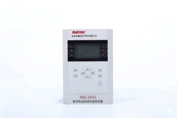
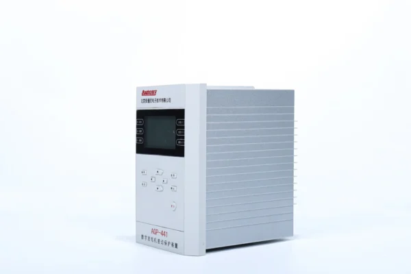
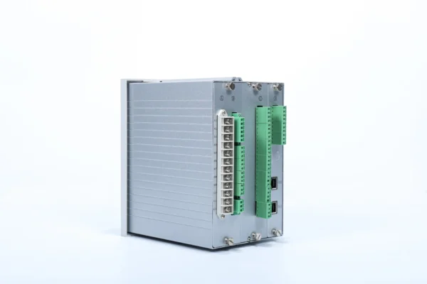
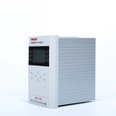
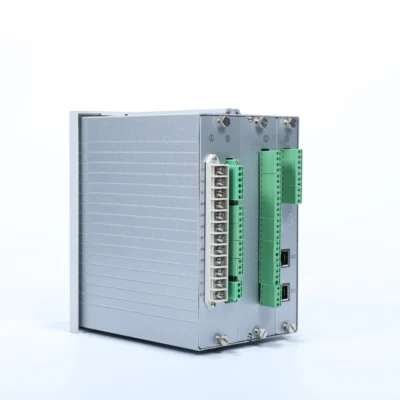
ASD-441H Comprehensive Motor Protection Relay
The ASD-441H Comprehensive Motor Protection Relay is primarily designed to protect motors.It is suitable for high-voltage motors in 3 kV to 35 kV systems,
and serves as bay-level equipment, performing protection, measurement, control, and communication functions.
Product Functions (ANSI)
50/51/46/47/48/49/27/50N/51N/59/66/60/74
Communication Mode
Optional: RS-485, CAN bus, Ethernet, IEC 60870-5-103 (IEC-103)
Send your requirements, we will quote for you within 12 hours
Description
Overview of Comprehensive Motor Protection Relay
The ASD-441H Comprehensive Motor Protection Relay is a comprehensive three-phase protection device designed for medium- and high-voltage motors in industrial and power system applications. It integrates motor overload, short-circuit, earth-fault, phase-sequence, negative-sequence, locked-rotor, stall, thermal and voltage protection in a single numerical relay.
Designed for motors in 3 kV to 35 kV systems, the ASD-441H provides protection, measurement, control, event monitoring and communication functions for motor feeders and bay-level applications.
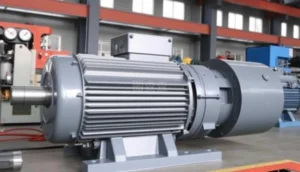
What Is a Comprehensive Motor Protection Relay?
A comprehensive motor protection relay continuously monitors electrical parameters such as current, voltage, frequency and phase sequence to detect abnormal operating conditions and faults. Depending on the protection configuration, it can issue alarms or trip commands to protect the motor from overload, short circuit, phase loss, earth fault, locked rotor, stall and other abnormal conditions.
ASD-441H Comprehensive Motor Protection Functions
The ASD-441H provides comprehensive motor protection with the following functions:
1. Overcurrent and Short-Circuit Protection
-
ANSI 50 – Instantaneous Overcurrent
-
ANSI 51 – Time Overcurrent
Provides protection against:
-
Phase faults
-
Overload-related overcurrent
-
Backup protection for downstream faults
2. Motor Thermal Protection
-
ANSI 49 – Thermal Overload
Protects against prolonged overload and excessive thermal accumulation, preventing insulation damage and premature motor failure.
3. Phase and Unbalance Protection
-
ANSI 46 – Negative-Sequence Protection
-
ANSI 47 – Phase-Sequence / Phase-Voltage Protection
Detects and protects against:
-
Phase loss
-
Phase reversal
-
Current imbalance
-
Voltage imbalance
4. Starting and Stall Protection
-
ANSI 48 – Locked Rotor Protection
-
ANSI 66 – Long Start / Start Supervision
Locked Rotor – Detects a rotor that fails to start or is mechanically blocked. The relay trips if starting current persists beyond the allowable locked rotor time, indicating that the motor cannot rotate freely.
Running Stall – Detects a sudden rotor stall during normal operation, typically caused by mechanical overload or jamming. The relay trips immediately or after a short time delay to prevent severe motor damage.
This distinction is particularly valuable for engineers, as locked rotor and running stall represent two different fault scenarios with different protection requirements.
5. Earth-Fault Protection
-
ANSI 50N / 51N – Instantaneous and Time-Delayed Earth Fault
Detects zero-sequence current associated with earth faults, providing sensitive protection for ground fault conditions.
6. Voltage Protection
-
ANSI 27 – Undervoltage
-
ANSI 59 – Overvoltage
Protects against voltage deviations that can cause motor overheating, torque reduction, or insulation stress.
7. Supervision
-
ANSI 60 – CT/VT Circuit Supervision
-
ANSI 74 – Trip Circuit Monitoring
Ensures protection system integrity by monitoring CT/VT secondary circuits and trip coil continuity, preventing protection failure due to wiring issues or circuit breaker problems.
Why Use a Comprehensive Motor Protection Relay?
Traditional motor protection uses multiple separate devices – increasing panel space, wiring complexity, and maintenance costs. A comprehensive relay integrates all functions into one unit, delivering complete protection, simpler engineering, and real-time visibility.
One Relay, Multiple Protection Functions
One device covers everything: overload + short circuit + earth fault + phase loss + stall + thermal + voltage protection. Reduces panel space and wiring costs.
Motor Starting Protection
Handles unique starting challenges – inrush current, extended start times, and locked rotor – with dedicated settings to prevent false tripping while ensuring safe motor acceleration.
Operational Monitoring
Real-time visibility of current, voltage, thermal state, and motor status. Enables predictive maintenance and informed decision-making.
Control & Communication
Seamless connectivity to SCADA, DCS, and PLC systems. Remote monitoring, remote start/stop, and instant alarm notifications.
Summary
One device delivers: simplified engineering, smaller footprint, lower cost, reliable protection, and real-time visibility – the smart choice for any motor control application.
Conventional Motor Protection vs Motor Differential Protection
| Feature | ASD-441H | 87M Differential Relay |
|---|---|---|
| Main Role | Comprehensive motor protection | Internal motor fault protection |
| Overload | ✓ | Usually separate function |
| Short Circuit | ✓ | ✓ |
| Earth Fault | ✓ | Depends on scheme |
| Phase Loss / Unbalance | ✓ | Not primary function |
| Locked Rotor | ✓ | Not primary function |
| Thermal | ✓ | Not primary function |
| Differential 87M | — | ✓ |
| Typical Application | General motor protection | Large / critical motors |
| Main Protection Principle | Current, voltage, thermal and logic | Differential current comparison |
Motor Voltage Range
| Application | Typical Voltage |
|---|---|
| Medium-Voltage Motor | 3 kV |
| Medium-Voltage Motor | 6 kV |
| Medium-Voltage Motor | 10 kV |
| High-Voltage Motor | Up to 35 kV |
Applications of the ASD-441H Comprehensive Motor Protection Relay
Power Plants
- auxiliary motors
- cooling pumps
- fans
- compressors
Water & Wastewater
- water pumps
- booster pumps
- treatment equipment
Mining
- conveyors
- ventilation fans
- pumps
- crushers
Chemical & Process Industries
- process pumps
- compressors
- fans
Industrial Plants
- large motors
- production line motors
- critical auxiliary motors
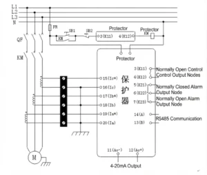
Comprehensive Motor Protection Relay Wiring Diagram
Setting Table
| No. | Description | Setting Range | Conversion Factor for Upload & Download |
|---|---|---|---|
| 1 | Control Word 1 | 0000~FFFF | – |
| 2 | Control Word 2 | 0000~FFFF | – |
| 3 | Control Word 3 | 0000~FFFF | – |
| 4 | Running Stall Time (Running Stall Delay) | 0.00~120.00s | ×100 |
| 5 | Starting Stall Time (Starting Stall Delay) | 0.00~120.00s | ×100 |
| 6 | Instantaneous Overcurrent Delay | 0.00~120.00s | ×100 |
| 7 | Negative Sequence Instantaneous Delay | 0.00~120.00s | ×100 |
| 8 | Phase Sequence Reversal Voltage Delay | 1.00~100.00s | ×100 |
| 9 | Under-voltage Protection Delay | 0.00~120.00s | ×100 |
| 10 | Zero-sequence Overcurrent Delay | 0.00~120.00s | ×100 |
| 11 | Overload Delay | 0.00~120.00s | ×100 |
| 12 | Start Delay | 0.00~120.00s | ×100 |
| 13 | Over-voltage Delay | 0.00~120.00s | ×100 |
| 14 | Running Stall Current Setting | 0.04~99.99A / 0.10~20.00A | ×100 |
| 15 | Starting Stall Current Setting | 0.04~99.99A / 0.10~20.00A | ×100 |
| 16 | Instantaneous Overcurrent Setting (During Start-up) | 0.04~99.99A / 0.10~20.00A | ×100 |
| 17 | Inverse-time Overcurrent Setting | 0.50~10.00A / 0.20~2.00A | ×100 |
| 18 | Negative Sequence Instantaneous Current Setting | 0.04~99.99A / 0.10~20.00A | ×100 |
| 19 | Negative Sequence Inverse-time Current Setting | 0.50~10.00A / 0.20~2.00A | ×100 |
| 20 | Spare Setting (Original Start Setting) | – | ×1 |
| 21 | Zero-sequence Overcurrent Setting | 0.02~5.00A / 0.50~99.00A | ×100 |
| 22 | Current Presence Setting | 0.20~5.00A | ×100 |
| 23 | Overload Current Setting | 0.04~99.99A / 0.10~20.00A | ×100 |
| 24 | Rated Current (Long-term Allowable Current of Motor) | 1.00~5.00A | ×100 |
| 25 | τ1 (Time Constant for Inverse-time Overcurrent) | 1.00~100.00s | ×100 |
| 26 | τ2 (Time Constant for Negative Sequence Inverse-time) | 1.00~100.00s | ×100 |
| 27 | Thermal Protection (Thermal Time Constant) | 1.00~100.00s | ×100 |
| 28 | Thermal Alarm Coefficient | 0.01~0.08 | ×100 |
| 29 | Under-voltage Protection Setting | 5.00~100.00V | ×100 |
| 30 | Over-voltage Setting | 5.00~100.00V | ×100 |
| 31 | Running Instantaneous Current Setting | 0.04~99.99A / 0.10~20.00A | ×100 |
| 32 | Overcurrent Setting | 0.04~99.99A / 0.10~20.00A | ×100 |
| 33 | Overcurrent Delay | 1.00~100.00s | ×100 |
| 34 | Current Blocking Setting (Blocking Value for Over/Under-voltage Protection) | 0.04~99.99A / 0.10~20.00A | ×100 |
| 35 | External Auto-start Delay | 0.100~655.350s | ×100 |
| 36~48 | Reserved | – | – |
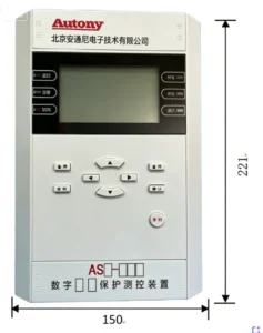
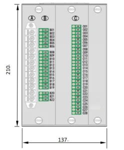
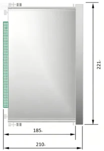
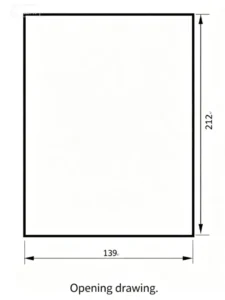
Outline and Installation Dimensions
FAQ
Q1. What is a motor protection relay?
A motor protection relay is a microprocessor-based digital device that protects electric motors from electrical faults and abnormal operating conditions, while also providing monitoring and communication functions.
Q2. What protection functions does the ASD-441H provide?
It provides comprehensive protection including: overcurrent (ANSI 50/51), thermal overload (ANSI 49), negative-sequence/unbalance (ANSI 46), phase-sequence (ANSI 47), locked rotor (ANSI 48), long start (ANSI 66), earth fault (ANSI 50N/51N), undervoltage (ANSI 27), overvoltage (ANSI 59), and supervision (ANSI 60/74).
Q3. What types of motors can the ASD-441H protect?
It is suitable for three-phase AC motors, including medium and high-voltage motors in industrial plants, mining, oil & gas, and commercial facilities.
Q4. What is the difference between overload and short-circuit protection?
Overload protection (ANSI 49/51) detects prolonged overcurrent conditions above rated current, using inverse-time curves to prevent thermal damage. Short-circuit protection (ANSI 50) operates instantly on very high currents, protecting against major faults such as phase-to-phase shorts.
Q5. What is locked-rotor protection?
Locked-rotor protection detects when a motor fails to start or is mechanically blocked. It trips when the starting current persists beyond the allowable locked-rotor time, preventing rapid thermal damage.
Q6. How does negative-sequence protection protect a motor?
Negative-sequence currents (unbalanced phase currents) induce reverse-rotating magnetic fields, which cause rotor heating. ANSI 46 detects this imbalance and trips before excessive rotor heating occurs, protecting the rotor bars from damage.
Q7. What is earth-fault protection for motors?
Earth-fault protection detects current leaking from the motor winding to ground. It is typically implemented using a core-balance CT or residual current calculation, providing sensitive protection against ground faults.
Q8. Can the ASD-441H protect motors during startup?
Yes. With dedicated settings for start supervision (ANSI 66), locked rotor (ANSI 48), and appropriate thermal bias, the relay allows normal inrush current while tripping for excessive starting times or stalled conditions.
Q9. What CT and PT signals are required?
The ASD-441H requires three-phase CT inputs for motor current measurement, and optional three-phase VT inputs for voltage measurement. CT and VT secondary ratings must match the relay specifications.
Q10. How is the motor protection relay configured?
Configuration is performed using software (via USB or communication port) or through the relay’s front panel interface. Parameters are entered according to motor data, CT/PT ratios, and protection coordination requirements.
Q11. How should motor protection settings be calculated?
Settings are calculated based on motor rated current, starting characteristics, thermal limits, and system coordination requirements. For detailed guidance, please refer to our Motor Protection Relay Setting Calculation Guide – which covers overload, locked rotor, stall/stop, negative-sequence, earth fault, and CT ratio settings.
Q12. Why does a motor protection relay trip during normal operation?
Possible causes include: incorrect CT ratio or polarity, improper protection settings, voltage unbalance, transient overcurrent, or actual motor fault conditions. A thorough review of settings and commissioning tests is recommended.
Q13. How is the ASD-441H tested before commissioning?
Commissioning tests include: CT/VT wiring verification, phase rotation check, primary injection testing, protection element function tests, trip circuit verification, and communication checks – all validated against the relay settings.
Q14. Does the ASD-441H support SCADA communication?
Yes. It supports standard communication protocols for SCADA system integration.
Q15. Which communication protocols are available?
Available protocols typically include Modbus RTU (RS-485), and depending on the model, IEC 61850 (GOOSE/MMS) for digital substation applications.
Q16. Can the motor protection relay be customized?
Yes. Please contact our sales team with your specific requirements for customization options.
Q17. What technical documents are provided?
We provide product datasheets, user manuals, connection diagrams, communication protocol guides, and setting calculation guides – all included with the product package.
Q18. Can the relay be supplied as part of a motor protection panel?
Yes. We can supply the ASD-441H as part of a complete motor protection panel solution – fully wired, configured, and tested to meet your specific project requirements.
Associated Products
2 reviews for ASD-441H Comprehensive Motor Protection Relay
Related products
High Quality
Stable performance, reliable design, ensuring safe operation for power system protection and grid stability.
Fast Delivery
Timely delivery to support your urgent orders and project schedules efficiently and professionally at any time.
Best Warranty
Professional Warranty: Reliable after-sales support for stable relay protection and long-term customer satisfaction.
xiao zhang –
This numerical motor protection relay integrates full-set protection for MV/ LV motors, stable operation and flexible parameter setting with multi communication ports, widely used in industrial pumps, fans and compressor units.
Jack –
Consistent performance across a wide temperature range.