

-
Leon Zhang sales consultant
-
Email: zxl635973785@gmail.com
-
Phone/WhatsApp: +86 13655813266
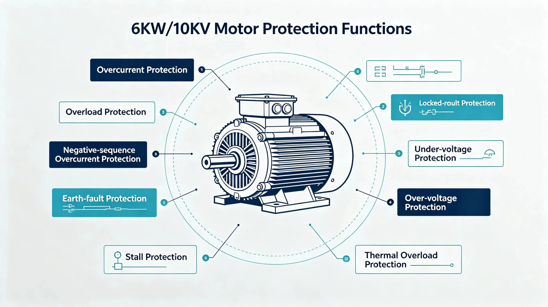
6kV/10kV Motor Protection Functions for Medium-Voltage Motors
6kV/10kV motor protection functions are the ANSI elements that guard one medium-voltage motor feeder: 50/51 overcurrent, 49 thermal, 46 negative sequence, 50N/51N earth fault, 27/59 voltage, 51LR locked rotor and 37 undercurrent, with 87M differential added from about 2 MW upward.
At a glance, on one MV motor feeder:
- 50/51 Overcurrent phase short circuits: a high instantaneous set covers the starter duty, the inverse-time element backs up downstream faults.
- 49 Thermal sustained overload: the relay models winding heat with a trip time that falls as current rises.
- 46 Negative sequence unbalance and single-phasing: negative-sequence current heats the rotor faster than positive-sequence current.
- 50N/51N Earth fault ground faults: the residual element sees the current the phase elements miss.
- 27/59 Voltage supply anomalies: undervoltage drops a running motor, overvoltage shortens winding life.
- 51LR Locked rotor a start that never reaches full speed: pickup above starting current, tripping on run-up time.
- 37 Undercurrent a motor running light or lost load, usually a process or coupling problem.
- 87M Differential faults inside the winding: only worth the CT cost from roughly 2 MW upward.
What Are 6kV/10kV Motor Protection Functions?
The contactor sees current only. The relay sees current, heat, sequence and ground, which is why short-circuit protection clears the fault first and the other elements decide whether the motor runs again.
6kV/10kV motor protection Functions on a MV feeder are monitoring and control schemes implemented through microprocessor-based relays to detect overload, short circuit, unbalance, and ground faults, and automatically trip or alarm to prevent equipment damage. A 6 kV or 10 kV motor is fed through a breaker, a MV cable and a set of CTs, and the relays on that feeder exist to catch five things: a short circuit, a sustained overload, an unbalanced supply, an earth fault, and a motor that never reaches speed. Anything that catches those five is what the relay on a 6 kV feeder is for.
Medium-voltage motors require dedicated protection due to high fault energy and complex fault modes like stall and single-phasing.
Compared to LV protection using basic thermal relays, 6kV/10kV protection offers multiple elements (differential, thermal, voltage), communication (IEC 61850, Modbus), and coordination: more sophisticated and costly, but essential for protecting critical motors.
ANSI Device Numbers on a 6 kV Motor Feeder
The short answer on ratings: the 6kV/10kV motor protection functions are the same list on either voltage, and what changes between 6 kV and 10 kV is the insulation stress margin and the CT size, not the elements themselves.
| Protection Function | ANSI Code | Purpose |
|---|---|---|
| Instantaneous Overcurrent | 50 | Short-circuit protection |
| Time Overcurrent | 51 | Backup/current fault protection |
| Earth Fault | 50N/51N or 50G/51G | Ground-fault protection |
| Thermal Overload | 49 | Thermal protection |
| Negative Sequence | 46 | Phase unbalance protection |
| Undervoltage | 27 | Abnormal voltage protection |
| Overvoltage | 59 | Excessive voltage |
| Undercurrent | 37 | Loss-of-load protection |
| Locked Rotor | 51LR / 48/14 depending on scheme | Stall/start protection |
| Differential | 87M | Internal motor fault protection |
| Loss of Excitation | 40 | Synchronous motor protection |
| Frequency | 81 | Abnormal frequency |
The Protection Elements You Will Actually Specify
Whatever the process asks of the motor, the 6kV/10kV motor protection functions come down to the element list below, and every one of them is set from the same handful of nameplate numbers.
50/51 Overcurrent Protection
Protects against phase-to-phase and three-phase short circuits. ANSI 50 provides instantaneous high-speed clearing for severe faults; ANSI 51 offers time-delayed backup. Set instantaneous element above motor starting current to avoid nuisance tripping.
49 Thermal Overload Protection
Models motor thermal condition to prevent insulation damage from sustained overload, repeated starts, or blocked cooling. Provides trip and alarm signals at preset thermal levels based on positive and negative sequence currents. The element itself is covered on the overload protection relay page.
46 Negative Sequence Protection
Detects current unbalance from voltage imbalance, single-phasing, or reversed phase sequence. Negative sequence currents cause severe rotor heating. Protects by tripping when I2/I1 ratio exceeds setting.
50N/51N Earth Fault Protection
Detects ground faults in motor and cables. 50N provides instantaneous clearing for severe faults; 51N offers time-delayed backup. Uses zero-sequence CTs for sensitive detection.
27 Undervoltage Protection
Prevents motor stalling and excessive current draw during low voltage conditions. Includes time delay to ride through transient disturbances. Coordinates with automatic transfer schemes.
59 Overvoltage Protection
Protects against insulation stress and core saturation from sustained overvoltage. Includes time delay for temporary voltage swells. Settings consider motor voltage tolerance.
51LR Locked Rotor Protection
Detects rotor failure to accelerate during starting. Sustained high current quickly damages motors. Trips if the motor exceeds the allowable starting time without reaching running speed. Locked rotor protection relay works the safe stall time out in full.
37 Undercurrent Protection
Detects loss of load conditions (pump cavitation, belt failure, mechanical disconnection). Common for pump motors. Settings coordinate with normal operation to avoid nuisance tripping.
87M Motor Differential Protection
Provides high-speed protection for internal motor winding faults, typically for motors above 2 MW. Compares terminal and neutral currents. Handles CT ratio differences and starting transients.
40 Loss of Excitation Protection
Applies to synchronous motors. Detects loss of field excitation that can cause overspeed or loss of synchronism. Trips when excitation falls below preset levels for specified time delay.
81 Frequency Protection
Detects over/under frequency conditions affecting motor operation and system stability. Applied in systems with islanding or generation shedding concerns. Coordinates with other frequency-sensitive equipment.
Summary Table
| ANSI | Function | Application |
|---|---|---|
| 50/51 | Overcurrent | Short circuits |
| 49 | Thermal Overload | Sustained overload |
| 46 | Negative Sequence | Unbalance, single-phasing |
| 50N/51N | Earth Fault | Ground faults |
| 27 | Undervoltage | Low voltage |
| 59 | Overvoltage | High voltage |
| 51LR | Locked Rotor | Starting failure |
| 37 | Undercurrent | Loss of load |
| 87M | Differential | Internal faults (≥2 MW) |
| 40 | Loss of Excitation | Synchronous motors |
| 81 | Frequency | Over/under frequency |
87M Differential Setting and CT Practice
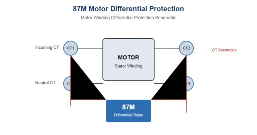
Motor differential protection (ANSI 87M) provides high-speed protection for internal winding faults in medium-voltage motors, typically applied to motors rated 2 MW and above. It compares currents at the motor terminals and neutral point using the current balance principle: under normal conditions, the two currents are equal and the differential current is near zero. When an internal fault occurs, the current balance is broken, generating a differential current that triggers instantaneous tripping.
Why It Matters: Internal winding faults can cause catastrophic motor failure if not cleared rapidly. 87M provides high-speed clearing (typically within 30–50 ms) that overcurrent protection alone cannot achieve.
Setting Example: For a 2000 kW / 6 kV motor with 300/1 A CTs, the differential pickup is typically set to 0.4 × Ie (where Ie is the motor rated secondary current, approximately 0.73 A), with a high-set element at 6 × Ie for severe internal faults.
How MV Motor Protection Differs from LV Motor Protection
An LV motor often runs on one electromechanical block with an overload relay and nothing else. MV motor protection on a 6 kV or 10 kV feeder has to do four things at once, which is why the element count is higher than the LV list.
First the fault energy is higher, so an internal winding fault has to be cleared in tens of milliseconds rather than seconds. Second the motor shares a breaker and a cable with the rest of the plant, so every trip has a system cost and has to be coordinated. Third the winding cannot be reached, so the thermal state has to be inferred from current instead of measured. Fourth the supply is a MV network, so insulation coordination, CT insulation level and arc-flash clearances all sit in the same budget.
That is the boundary this page keeps, and MV motor protection is where the element list on a motor feeder grows longest. The generic element-by-element list of motor protection relay functions sits on its own page, and the choice between vendor relays has its own checklist in how to choose a motor protection relay.
How to Size the Function Set for One Medium-Voltage Motor
Selecting the right protection functions for a medium-voltage motor requires evaluation of motor characteristics, system conditions, and process requirements. The medium-voltage protection relay selection guide runs the same list at feeder level. The following checklist guides the selection process. Three of its rows decide settings before any menu is opened.
Selection Checklist
| Factor | What to Check | Impact on Protection Selection |
|---|---|---|
| Motor Rated Power | kW or MW rating | Determines whether differential protection is required (typically ≥2 MW) |
| Rated Voltage | 6 kV or 10 kV | Affects insulation coordination and CT/VT ratings |
| Motor Type | Induction or synchronous | Synchronous motors require additional protection (40, 81) |
| Starting Method | DOL, star-delta, VFD, soft starter | Affects starting current, starting time, and coordination settings |
| Starting Current | Multiple of rated current (e.g., 6× In) | Critical for setting overcurrent and locked rotor protection |
| Starting Time | Seconds (e.g., 5–15 s) | Determines thermal overload and stall protection settings |
| Grounding System | Solid, low-resistance, or high-resistance grounded | Determines earth fault protection type and sensitivity |
| CT/PT Configuration | Ratio, class, location | Affects measurement accuracy and protection performance |
| Differential Protection | Required for motors ≥2 MW | 87M provides high-speed internal fault protection |
| Process Criticality | Critical or non-critical | Determines whether redundant protection, communication, and alarm functions are required |
Selection Summary Table
| Motor Characteristic | Recommended Protection Functions |
|---|---|
| Induction motor, <2 MW, DOL start | 50/51, 49, 46, 50N/51N, 27, 59, 51LR, 37 |
| Induction motor, ≥2 MW, DOL start | Above + 87M |
| Synchronous motor, ≥2 MW | Above + 40 (Loss of Excitation), 81 (Frequency) |
| Critical process motor | Redundant protection + communication (IEC 61850/Modbus) |
| VFD-driven motor | Adapted protection (consider VFD harmonics and output frequency) |
Key Considerations
- Differential protection (87M) is typically required for motors rated 2 MW and above to provide high-speed clearing for internal winding faults.
- Starting conditions must be accurately defined. Starting current and starting time directly affect overcurrent, thermal, and locked rotor settings.
- Grounding system determines earth fault protection: solidly grounded systems use 50N/51N; high-resistance grounded systems may require sensitive 51N with alarm-only logic.
- Process criticality influences protection scheme complexity: critical motors may require redundant protection relays, dual CTs, and communication to SCADA.
- CT selection is essential: CT ratio must accommodate starting current without saturation; class should be 5P20 or better for differential protection.
CT, VT and Wiring Choices on a 6 kV Feeder
The 6kV/10kV motor protection functions above cannot be entered at all if the measuring chain is wrong, so the CT ratio, the burden and the secondary wiring are checked before any setting number is keyed in.
The measuring chain decides whether the function set above can be set at all. On a MV motor the CTs sit in the cable box or the MV panel, they carry the motor starting current for several seconds, and they have to stay linear over the range that matters for 51 pickup and 49 memory. A CT that saturates early gives a relay that reads low during starting and trips late on a real fault.
Practically: pick the ratio so the motor rated secondary current sits near the middle of the relay range, use accuracy Class 5P20 for the differential and earth fault elements, and keep the neutral-end CTs identical to the line-end CTs where 87M is applied. The VT follows the same rule for 27, 59 and 81. On MV the CT also has a BIL requirement, so a CT that is electrically right but under-rated for 6 kV or 10 kV is a rejection at commissioning. On a 10 kV machine the medium voltage motor relay and its CTs sit at the same insulation level, and they are bought together.
Coordination Study and Commissioning Tests
A 6kV/10kV motor protection function set that survives the study still has to be proved on the bench, and the two tests that catch most commissioning mistakes are the 51 injection and an 87M stability check at the highest through-current.
A MV motor function set is only as good as its coordination. The motor starting curve has to sit below the 51 and 51LR curves, the 49 curve has to sit below the motor thermal limit, and 51 has to sit above the incoming feeder protection so a motor fault clears at the motor rather than behind the transformer.
At commissioning three tests carry most of the value: primary injection on the trip circuit to confirm the breaker opens, secondary injection on 50/51 and 51LR to confirm the time to trip matches the study, and a thermal replica check where the relay is driven to the alarm level and then left to cool back down without tripping.
Medium-Voltage Motor Protection FAQ
Q1. What protection functions are required for a 6kV motor?
A 6kV motor typically requires a suite of protection functions to address various fault conditions: overcurrent (50/51) for short-circuit protection, thermal overload (49) for sustained overload, negative-sequence (46) for unbalance and single-phasing, earth fault (50N/51N) for ground faults, undervoltage (27) and overvoltage (59) for voltage anomalies, locked rotor (51LR) for starting failures, and undercurrent (37) for loss of load. For motors rated 2 MW and above, differential protection (87M) is also required.
Q2. What protection functions are required for a 10kV motor?
A 10kV motor requires the same core protection functions as a 6kV motor: 50/51, 49, 46, 50N/51N, 27, 59, 51LR, and 37. The key difference lies in insulation coordination and CT/VT ratings. 10kV systems require higher insulation levels and different CT/VT ratios. For synchronous motors, additional protection such as loss of excitation (40) and frequency protection (81) are required.
Q3. What ANSI codes are used for medium-voltage motor protection?
| ANSI Code | Protection Function |
|---|---|
| 50/51 | Overcurrent Protection |
| 49 | Thermal Overload Protection |
| 46 | Negative Sequence Protection |
| 50N/51N | Earth Fault Protection |
| 27 | Undervoltage Protection |
| 59 | Overvoltage Protection |
| 51LR | Locked Rotor Protection |
| 37 | Undercurrent Protection |
| 87M | Motor Differential Protection |
| 40 | Loss of Excitation Protection (synchronous motors) |
| 81 | Frequency Protection (synchronous motors) |
Q4. What is 87M motor differential protection?
87M motor differential protection is a high-speed protection scheme that compares currents at the motor terminals and neutral point to detect internal winding faults. Under normal conditions, the two currents are equal and differential current is near zero. When an internal fault occurs, the current balance is broken, generating a differential current that triggers instantaneous tripping. It is typically applied to motors rated 2 MW and above to provide high-speed clearing that overcurrent protection alone cannot achieve.
Q5. What is 49 motor thermal protection?
49 motor thermal protection is a thermal overload protection that models the thermal condition of the motor based on current measurements. It protects against insulation damage from sustained overload, repeated starts, or blocked cooling. The relay calculates the thermal state using a thermal model that accounts for both positive and negative sequence currents, and provides trip and alarm signals at preset thermal levels.
Q6. What is 46 negative-sequence protection?
46 negative-sequence protection detects current unbalance caused by voltage imbalance, single-phasing, or reversed phase sequence. Negative sequence currents produce rotor heating that builds much faster than positive-sequence current of the same magnitude. The relay measures negative sequence current (I2) and compares it against positive sequence current (I1). When the I2/I1 ratio exceeds the setting, the relay initiates trip or alarm.
Q7. What is 51LR locked-rotor protection?
51LR locked-rotor protection detects when the motor rotor is unable to rotate during starting attempts. This condition results in sustained high current that can quickly damage the motor. The relay monitors current magnitude and duration during starting, so if the motor fails to accelerate within the allowable starting time, the relay trips to prevent thermal damage.
Q8. What is the difference between 6kV and 10kV motor protection?
The core protection functions are the same for 6kV and 10kV motors. Both require overcurrent, thermal, negative sequence, earth fault, undervoltage, and locked rotor protection. The key differences lie in:
- Insulation coordination: 10kV motors require higher insulation levels and larger clearances
- CT/VT ratings: Different ratios and insulation classes are required
- Motor sizing: 10kV motors typically have higher power ratings, making differential protection more common
- System grounding: Grounding practices may differ, affecting earth fault protection sensitivity
Q9. How are motor protection relay settings selected?
Protection relay settings are selected based on motor nameplate data, system conditions, and coordination requirements. Key inputs include:
- Motor rated power, voltage, and current
- Starting method and starting current (typically 5–7 × In)
- Starting time (typically 5–15 seconds)
- Thermal characteristics (thermal limit curves from manufacturer)
- Grounding system type (solid, low-resistance, or high-resistance)
- CT/VT ratios and accuracy class
- Coordination with upstream and downstream protection devices
The ANSI motor protection functions on a 10 kV machine are the same set as on a 6 kV one, so the 6kV/10kV motor protection functions differ in rating rather than in scope. A function list copied out of a datasheet is not a scheme either: the numbers have to come from the nameplate, the starting curve and the grounding system, and the result is checked with primary injection before the motor is handed to the process.
Related reading: motor protection relay functions for the element-by-element detail, motor protection relay selection for how the set is shortlisted, and medium-voltage protection relay selection when the same feeder also carries transformers or feeders.
Conclusion
6kV/10kV motor protection functions are not a fixed list you copy from a datasheet. The floor is 50/51, 49, 46 and 50N/51N for every induction motor on a 6 kV or 10 kV feeder, 27 and 59 where the process cannot ride through a voltage dip, 51LR and 37 where starting or load matters.
Add 87M once the motor reaches roughly 2 MW and the CTs are worth the second set of conductors. Above that rating it is the only element that sees faults inside the winding. Three checks then decide whether the scheme works: the CT ratio and accuracy class, the coordination study against the upstream breaker, and a primary injection test before the motor is handed to the process.
Technical References
| Source | What it covers | Type | Edition |
|---|---|---|---|
| IEEE C37.96-2012 | Guide for AC motor protection, which fixes how 49, 46, 51LR and 50N/51N are applied | IEEE Guide | 2012 |
| ANSI/IEEE C37.2-2022 | Device function numbers used throughout this article: 50, 51, 49, 46, 50N/51N, 27, 59, 37, 51LR, 48, 87M, 40, 81 | IEEE Standard | 2022 |
| IEC 60255-1:2022 | Generic requirements and testing for measuring and protection relays | IEC Standard | 2022 |
| IEC 60255-187-1:2021 | Functional requirements for differential protection of motors, generators and transformers | IEC Standard | 2021 |
| IEC 61869-2:2012 | Current transformers for protective relaying, which sets the ratio and accuracy used here | IEC Standard | 2012 |



About Author

Hello, I'm Leno Zhang. I have 15 years of experience in the power relay protection industry with extensive pre-sales and after-sales project experience. Our company specializes in various complete sets of relay protection and automation equipment. I can assist customers in solving all practical on-site project challenges and provide optimal integrated solutions.
Tell Us Your Requirement
High Quality
Stable performance, reliable design, ensuring safe operation for power system protection and grid stability.
Fast Delivery
Timely delivery to support your urgent orders and project schedules efficiently and professionally at any time.
Best Warranty
Professional Warranty: Reliable after-sales support for stable relay protection and long-term customer satisfaction.