-
Leon Zhang sales consultant
-
Email: zxl635973785@gmail.com
-
Phone/WhatsApp: +86 13655813266

Principle and Commissioning Method of Transformer Differential Protection Device
Principle of Transformer Differential Protection
The basic principle of differential protection adopted by protection relays for transformer and relays for transformer protection is to compare the magnitude and phase of currents on both sides of the transformer. Under normal operating conditions, the currents on both sides are equal in magnitude and identical in phase. When an internal fault occurs inside the transformer, a deviation appears between the currents on the two sides. Based on this characteristic, differential protection is implemented by these relays to isolate the transformer and protect it against internal faults.
Commissioning Methods
Fully understand transformer parameters and protection device principles before commissioning
Check and record parameters: Record the transformer nameplate parameters (rated capacity, voltage level, connection group) and the transformation ratio of current transformers (CTs).
Read technical manuals: Master the differential protection principle of the protection device and phase compensation modes (Y→Δ or Δ→Y).
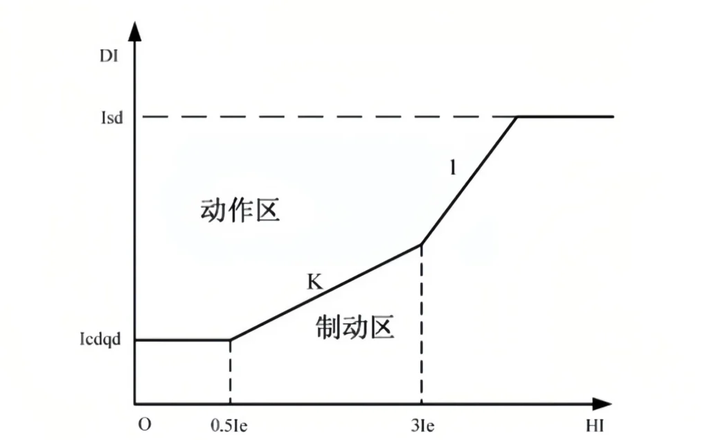
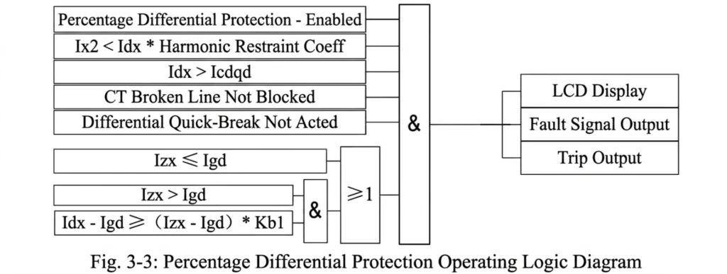
Familiarize with operating equations: Understand the operating logic of percentage differential protection, differential instantaneous overcurrent tripping, and harmonic restraint.
Setting calculation
Calculate basic parameters in accordance with transformer specifications and relay protection setting criteria:

Balance coefficient: Take the high-voltage side as the reference to calculate the balance coefficient of each side.
Differential starting current: Generally set to (0.3~0.5) times of Ie.
Differential instantaneous trip setting: Generally set to (5~10) times of Ie.
Percentage restraining characteristic parameters: inflection point current and restraining coefficient.
Input the calculated protection settings into the transformer differential protection device.
Carry out tests on the differential protection device by using a relay protection tester
Accuracy Test
Verify the sampling accuracy of the protection device, including voltage, current, power factor, frequency and other measured quantities.
Protection Functional Test
Balance Current Calibration
Ensure that under normal operating conditions, the differential current displayed by the transformer differential protection device is close to zero and within the allowable error range.
Percentage Differential Protection Test
Apply through current: The differential current shall be lower than the starting value, and the protection shall not operate.
Apply internal short-circuit current: The differential current exceeds the starting value, and the protection shall operate correctly.
Inject current containing second harmonic components to verify the harmonic restraint function.
After the above tests, verify the actual starting value and inflection point value of the transformer differential protection.
Record key data after commissioning
Measured value of differential starting current
Measured value of differential instantaneous trip current
Test points of percentage restraining characteristic curve (at least 3~5 points)
Measured harmonic restraint coefficient
Results of overall linkage test
Compile and issue the test report.
Conclusion
Transformer differential protection constitutes transformer primary protection, which operates only when a fault occurs inside the transformer. Transformer overload protection and transformer ground fault protection act as secondary protections, covering transformer bushings and external adjacent areas.
The above is an introduction to transformer differential protection and is provided for reference only.
About Author

Hello, I'm Leno Zhang. I have 15 years of experience in the power relay protection industry with extensive pre-sales and after-sales project experience. Our company specializes in various complete sets of relay protection and automation equipment. I can assist customers in solving all practical on-site project challenges and provide optimal integrated solutions.
Tell Us Your Requirement
High Quality
Stable performance, reliable design, ensuring safe operation for power system protection and grid stability.
Fast Delivery
Timely delivery to support your urgent orders and project schedules efficiently and professionally at any time.
Best Warranty
Professional Warranty: Reliable after-sales support for stable relay protection and long-term customer satisfaction.