

-
Leon Zhang sales consultant
-
Email: zxl635973785@gmail.com
-
Phone/WhatsApp: +86 13655813266
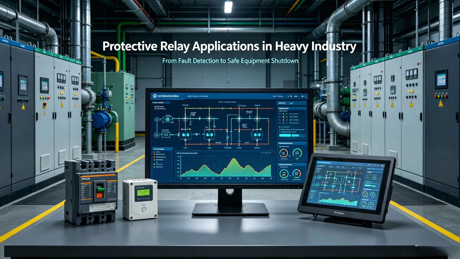
Protective Relays in Heavy Industry: Steel, Cement, Mining and Chemicals
Protective Relays in Heavy Industry at a Glance
Protective relays in heavy industry are numerical IEDs that read current, voltage, frequency and temperature on motors, transformers, generators and feeders in steel, cement, mining, chemical and oil and gas plants, and trip the breaker when a measured value leaves its setting.
The function set is close to what a utility relay carries. The duty is not. A conveyor or kiln drive pulls six to ten times rated current for ten to thirty seconds while it starts. Fault levels in a plant substation saturate a CT within two cycles. Conductive dust tracks across terminal blocks. And the process behind the breaker cannot simply stop, because one unplanned hour in a steel mill costs more than the relay cabinet did.
That duty is why settings, not model numbers, decide whether a protection scheme holds up in service.
Six functions cover most of what gets specified, and all six are named by ANSI device numbers from ANSI/IEEE C37.2-2022:
- ANSI 50/51, instantaneous and time-delayed overcurrent: feeder and motor short circuits, graded against the downstream device.
- ANSI 50N/51N, earth fault: the single most common fault in cable-heavy industrial networks.
- ANSI 49, thermal replica: locked rotor, and too many starts in too short a window.
- ANSI 46, negative sequence: phase unbalance and single phasing upstream of a drive.
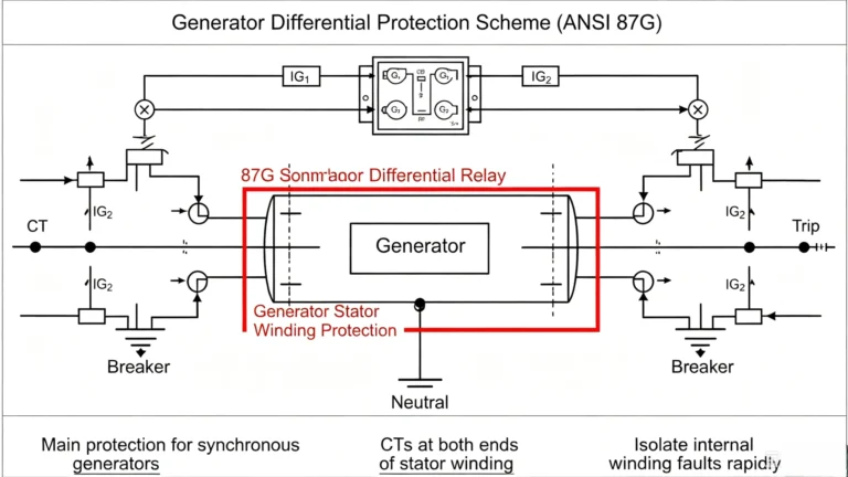
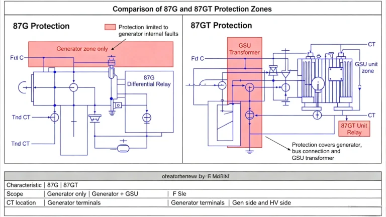
- ANSI 87, differential: main protection on transformers, generators and motors above roughly 2 MVA.
- ANSI 27/59 and 81, voltage and frequency: bus transfer, load shedding and islanding detection.
Four standard families set what the device must do. IEC 60255-1:2022 fixes the common requirements every measuring relay is tested to, IEC 60255-151:2009 covers the overcurrent function, IEC 60255-149:2013 the thermal replica and IEC 60255-187-1:2021 differential protection. Immunity to the electromagnetic noise of a plant substation sits in EN IEC 60255-26:2025. Large motor practice is written up in IEEE C37.96-2012, and arc flash incident energy comes out of the model in IEEE 1584-2018.
The rest of this page follows one thread: what each plant type actually breaks, which functions catch it, how the grading is done, and what to verify before you buy.
Start with the plant, not the catalogue.
Why Protective Relays Matter in Heavy Industry
Protective relays in heavy industry applications serve as the core safety and stability guarantee for high-power electrical systems in mining, oil and gas, steel, cement, chemical, and large-scale manufacturing plants. Unlike commercial and light industrial power systems, heavy industry electrical infrastructure features high voltage, large load current, high short-circuit capacity, and continuous 24/7 operation. A single unisolated electrical fault can lead to equipment burnout, production shutdowns, arc flash accidents, and even personnel casualties.
Heavy industrial power systems frequently face predictable electrical risks, including short circuits, overcurrent and overload, ground faults, motor stall failures, voltage and frequency deviations, and transformer/generator internal faults. High-quality protective relays detect abnormal electrical signals in milliseconds, trigger selective tripping, isolate faulty equipment, and retain normal operation of healthy circuits. This effectively minimizes equipment damage, cuts unplanned downtime costs, and complies with global industrial electrical safety specifications.
What Is a Protective Relay in a Power System?
A protective relay is a core sensing and control device for power system protection. Its basic function is to monitor real-time electrical parameters (current, voltage, frequency, phase sequence) of power equipment, identify abnormal and fault states, and output trip or alarm signals to circuit breakers and industrial control systems.
Many EPC engineers and on-site project teams confuse protective relays with circuit breakers. The two devices work collaboratively but undertake distinct roles: protective relays judge faults and issue commands, while circuit breakers execute current interruption.
In standard industrial protection schemes, protective relays work with Current Transformers (CTs) and Voltage Transformers (VTs) to collect real-time system data, then interact with breakers and SCADA systems to form a closed-loop protection system.
Three generations of protective relays are widely used in heavy industry:
- Electromechanical relays: Mature, low-cost, suitable for simple low-end industrial distribution systems
- Static relays: Solid-state design, improved anti-interference performance, no mechanical wear
- Numerical relays: Intelligent multi-functional devices with fault recording, oscillography, remote communication, and self-diagnosis functions, becoming the mainstream for modern heavy industrial projects
Why Heavy Industry Needs Professional Electrical Protection
Protective relays in heavy industry are bought for one reason: the plant cannot absorb an unplanned stop. Everything in this section follows from that.
1. High-Power Core Electrical Equipment
Bigger machines mean bigger fault current, and bigger fault current means the CT has to be checked rather than assumed.
Heavy industry relies on large-scale power equipment including high-power industrial motors, distribution and power transformers, synchronous generators, medium and high-voltage switchgear, and industrial substations. These devices carry system-level loads; unprotected faults will trigger cascading failures across the entire plant power grid.
2. Extreme Short-Circuit Fault Risks
Industrial substations and high-power equipment generate extremely high short-circuit fault currents during failures. Uncontrolled fault currents cause severe arc flash, burn switchgear contacts, damage winding insulation, and expand fault scope. Fast-acting protective relays ensure instantaneous fault isolation to reduce equipment loss and safety hazards.
3. Zero-Tolerance for Unplanned Shutdowns
Heavy industrial production is continuous and process-bound. Unplanned power outages lead to batch product scrapping, production line restart costs, and delayed project delivery. Scientific protection coordination ensures only faulty branches trip, maximizing power system availability and production continuity.
4. Harsh On-Site Operating Environments
Industrial sites feature heavy dust, mechanical vibration, high temperature and humidity, corrosive gas, and strong electromagnetic interference from frequency converters and high-power equipment. Ordinary civil protection devices are prone to nuisance tripping or failure. Industrial-grade protective relays pass strict EMC and environmental adaptation tests to ensure long-term stable operation.
Common Types of Protective Relays Used in Heavy Industry
Every industrial protection relay is specified by the ANSI functions it carries rather than by its model name, because the design office, the panel builder and the commissioning crew are often three different companies reading one drawing. ANSI/IEEE C37.2-2022 is the edition that numbering now comes from. Protective relays in heavy industry service cluster into the types below:
| Relay Type | ANSI Function | Typical Industrial Application |
|---|---|---|
| Overcurrent Relay | 50/51 | Medium/high-voltage feeders, large motors, distribution transformers |
| Earth Fault Relay | 50N/51N | System ground fault protection for all industrial power loops |
| Differential Protection Relay | 87 | Key protection for main transformers, generators, large industrial motors |
| Motor Protection Relay | 49, 46, 48, 50/51 | Integrated protection for process-driven large motors |
| Under/Overvoltage Relay | 27/59 | Busbar, feeder, and motor voltage anomaly protection |
| Under/Overfrequency Relay | 81U/81O | Island operation and grid-connected industrial power systems |
| Reverse Power Relay | 32 | Prevent generator reverse power feeding and unit damage |
| Distance Relay | 21 | Long-distance industrial transmission line fault protection |
| Thermal Overload Relay | 49 | Thermal accumulation protection for motors and transformers |
| Phase Sequence Relay | 47 | Prevent three-phase motor reverse rotation and equipment failure |
| Negative Sequence Relay | 46 | Motor and generator phase loss and unbalanced load protection |
Protective Relay Applications in Heavy Industry
Five plant types account for most heavy industry relay applications, and each one breaks the same equipment differently. That difference, not the relay model, is what sets the settings:
| Industry | Dominant load | What fails first | Functions that matter most |
|---|---|---|---|
| Steel | Rolling mill and furnace drives, arc furnace transformer | Insulation breakdown from heat and conductive dust; repeated heavy starting | 49, 46, 48, 50/51, 87 on the furnace transformer |
| Cement | Kiln drive, raw mill, bucket elevator, long conveyors | High inertia stalls and long run-up; limestone dust on terminals | 49, 48, 51, 27/59 |
| Mining | Conveyors, crushers, hoists, long trailing cable runs | Earth faults on damaged trailing cable; voltage drop at the face | 50N/51N, 51, 27, 46 |
| Chemical and petrochemical | Process pumps, compressors, Ex-area motors | Corrosion and moisture ingress; hazardous area certification gaps | 49, 46, 50N/51N, 87 |
| Pulp and paper | Paper machine section drives, refiners, chippers | Bus transfer dips and regenerative drive back-feed | 27/59, 81, 50/51, 32 |
1. Industrial Large Motors
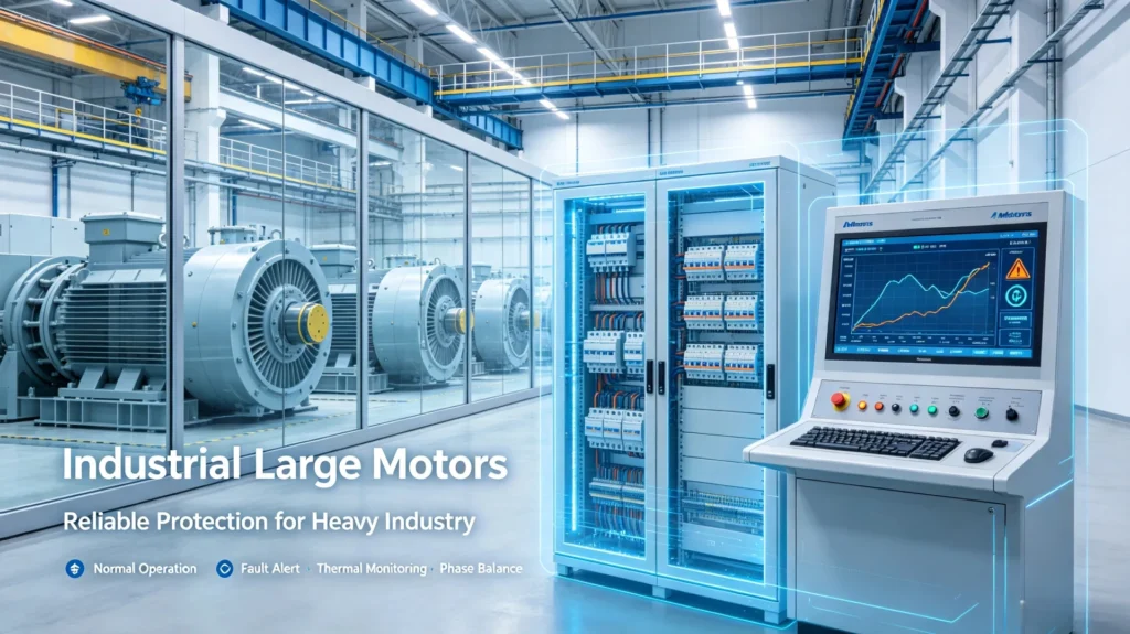
Motors are the most widely used core equipment in heavy industry, facing frequent starting impact, load fluctuation, and harsh operating conditions. Professional motor protection relays provide full-scenario protection including overload, short circuit, locked-rotor, phase loss, negative sequence unbalance, and thermal overheating. This protection scheme is standard for steel mills, cement plants, mining sites, oil and gas facilities, and chemical processing plants.
2. Industrial Transformers
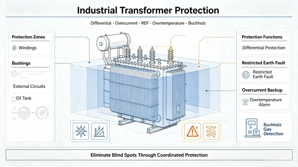
Transformers are the power conversion core of industrial substations. The standard protection configuration includes differential protection (main protection), overcurrent and restricted earth fault protection (backup protection), overtemperature protection, and Buchholz gas protection for oil-immersed transformers. Reasonable protection coordination eliminates blind spots for internal and external transformer faults.
3. Industrial Generators
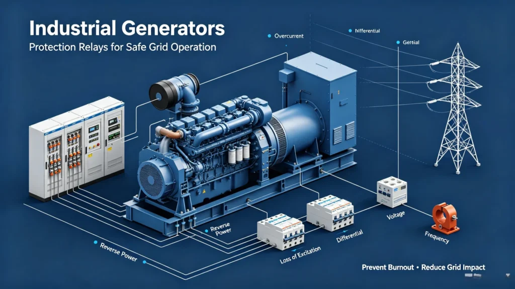
For self-provided generator sets in factories and grid-connected distributed power stations, relays provide overcurrent, reverse power, loss-of-excitation, differential, voltage, and frequency protection. These functions avoid generator burnout and grid impact caused by abnormal operating conditions.
4. Switchgear and Feeders
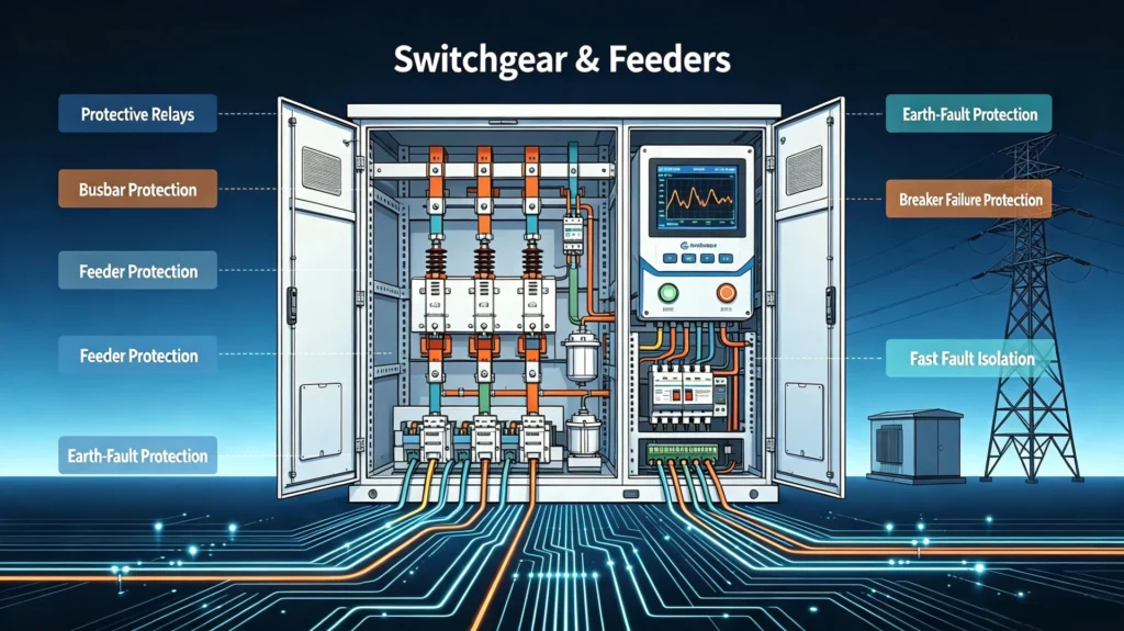
Medium- and high-voltage switchgears and outgoing feeders undertake power-distribution tasks. Protective relays in power systems provide short-circuit, earth-fault, busbar, feeder, and breaker-failure protection to ensure rapid isolation of distribution-network faults and prevent power-supply paralysis.
5. Industrial Substations
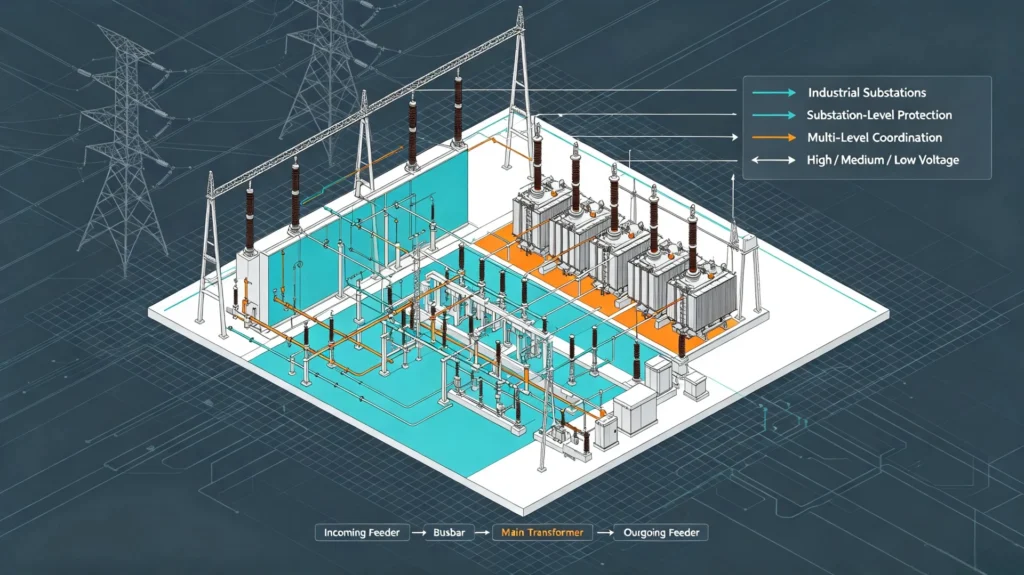
The protective relay in substation realizes substation-level protection covering incoming feeder, busbar, main transformer, and outgoing feeder protection. Multi-level protection coordination between high, medium, and low voltage levels ensures hierarchical fault disposal and improves power system stability.
Core Protective Relay Functions for Heavy Industry
Protective relays in heavy industry usually ship as one device carrying six or seven of the functions below, not as separate units.
Overcurrent Protection (ANSI 50/51)
Divided into instantaneous overcurrent (ANSI 50) and time-delayed overcurrent (ANSI 51). Instantaneous protection responds to severe short-circuit faults within milliseconds; time-delayed protection targets minor overload and slow-developing faults, widely used in feeders, motors, and transformer backup protection.
Earth Fault Protection (ANSI 50N/51N)
Ground faults are the most frequent faults in industrial power systems, caused by cable aging, insulation damage, and equipment leakage. Relays judge faults through residual current and zero-sequence current detection, effectively protecting personnel safety and preventing insulation breakdown accidents.
Differential Protection (ANSI 87)
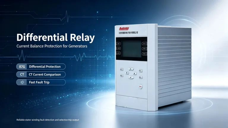
Differential protection judges internal faults by comparing current values at the inlet and outlet of protected equipment. It features high sensitivity and fast action, serving as the main protection for key equipment such as large transformers, generators, and high-power motors.
Thermal Protection (ANSI 49)
Motor thermal limits are a process constraint as much as an electrical one.
Simulate equipment thermal accumulation characteristics in real time, monitor motor winding and transformer temperature rise, and avoid insulation aging and equipment burnout caused by long-term overload operation.
Voltage & Frequency Protection (ANSI 27/59/81)
Abnormal grid voltage and frequency cause motor speed deviation, equipment resonance, and load tripping. Relays monitor real-time parameters and execute alarm or trip actions to stabilize industrial load operation.
How Protective Relays Improve Plant Reliability
Reliable tripping moves four numbers a plant manager already tracks:
- Reduce core equipment damage rate and lower replacement and maintenance costs
- Minimize unplanned production downtime and improve plant operation efficiency
- Realize selective fault isolation to avoid large-area power outages
- Support predictive maintenance through fault recording and data analysis
- Improve on-site personnel electrical safety protection level
- Integrate with SCADA and plant automation for remote monitoring and remote setting changes
Protection Coordination in Heavy Industrial Power Systems
An industrial protection relay is only as good as the grading around it. A perfect setting on one device still trips the wrong breaker if the device upstream is set faster.
Protection coordination is the core of industrial power system design, determining whether the protection system can act accurately without misoperation or refusal. It refers to the matching of action current and time between primary and backup protection of all levels of equipment.
Core Coordination Logic
Grading runs downstream first. The device closest to the fault clears it, and everything upstream waits.
Primary protection acts first for faults; backup protection acts only when primary protection or breakers fail, ensuring no unprotected dead zones.
Key Coordination Parameters
Pickup current, time multiplier setting (TMS), system short-circuit current, CT ratio, relay characteristic curve, and breaker clearing time.
Standard Industrial Coordination Sequence
Write the sequence down. Most coordination arguments on site are really arguments about which drawing is current.
Load terminal equipment → Motor/feeder protection → Switchgear protection → Transformer protection → Main incoming feeder protection
Heavy Industry Protection Scheme: A Selection Guide
Most selection mistakes happen before the relay is chosen, at the point where system data is assumed instead of measured. Work the five checks below in order. A heavy industry protection scheme that skips the first one is usually re-graded once the real fault study comes back.
1. Confirm System Electrical Parameters
Measure it. Nameplate data is not a fault study.
Match relay specifications according to system rated voltage, rated current, frequency, short-circuit capacity, and grounding mode to ensure device matching with grid characteristics.
2. Match Load Equipment Parameters
Select targeted protection schemes based on motor rated power, transformer capacity, generator parameters, and load fluctuation characteristics.
3. Clarify Protection Function Requirements
Confirm required ANSI functions, protection stages, alarm/trip output logic, and customized protection logic according to project design specifications.
4. Adapt to On-Site Environmental Conditions
Dust, heat and vibration set the enclosure rating, and the enclosure rating decides whether the relay sees a second summer.
Select industrial-grade relays with wide temperature resistance, vibration resistance, dustproof, corrosion-resistant, and high EMC anti-interference performance to adapt to harsh industrial environments.
5. Support System Communication Integration
Pick the protocol before ordering, not after.
Priority should be given to relays supporting Modbus RTU/TCP, IEC 61850, and Ethernet communication to meet SCADA remote monitoring, remote parameter configuration, and centralized management requirements for intelligent factories.
Numerical Relays in Continuous Process Service
Two changes drove the switch: settings replaced wiring, and disturbance records stopped costing extra.
Electromechanical and static relays each do one job, and their logic is fixed by the wiring. A plant that needs a second motor starting regime, or that re-grades a feeder after an expansion, cannot get either without changing hardware. Numerical relays moved that logic into settings:
- Multi-function integration: One device realizes multiple protection functions, saving cabinet space and project cost
- Data recording: Support fault recording, oscillography, and event log for post-fault analysis
- Self-diagnosis: Real-time self-check of device hardware and software status to avoid hidden faults
- Remote operation: Support remote parameter setting, monitoring, and upgrade
- Strong expandability: Adapt to subsequent project capacity expansion and function upgrade
One caveat from site work. A numerical unit with twenty enabled functions takes far longer to commission than an electromechanical one with a single element. Enable what the protection study calls for and leave the rest disabled, because every unused element is still a setting that has to be proved or formally marked out.
Relay Testing and Commissioning in Industrial Plants
Testing is where a protection study either holds up or falls apart. Two complaints dominate after handover: the relay trips when it should not, and it does not trip when it should. Both are almost always setting or wiring errors rather than relay failures, and both are caught by injection before the plant is energised.
Common Testing Methods
Secondary injection testing, primary injection testing, functional logic testing, trip circuit testing, and communication protocol testing.
Standard Commissioning Process
- Review protection design drawings and parameter settings
- Verify on-site wiring and CT/VT connection correctness
- Input accurate relay setting parameters
- Complete secondary injection testing to verify protection logic
- Test breaker trip execution performance
- Verify alarm signal and SCADA communication data
- Sort out and file commissioning test reports
The relay itself is type and routine tested to IEC 60255-1:2022, with immunity in EN IEC 60255-26:2025. Secondary injection is the normal site method and proves the logic and the trip path. Primary injection is slower to set up and is reserved for the CT circuit, because it is the only test that finds a reversed core or a wrong ratio on a wound CT.
Do it before energisation. A ratio error found afterwards means a shutdown.
On-Site Faults and Fixes
Four faults cause nearly every call-out.
Nuisance Tripping
Check the settings before blaming the relay.
Caused by unreasonable parameter settings, motor starting impulse current, CT saturation, and electromagnetic transient interference. Solution: Optimize time-current curves, set starting delay locking, and select high-precision CTs.
Failure to Trip
This is the one that ends in a fire, so it gets tested first.
Caused by wrong wiring, relay hardware failure, DC control power loss, and breaker stuck faults. Solution: Standardize construction wiring, regularly inspect control power and executing mechanisms.
Poor Protection Coordination
Caused by mismatched time-current settings and incorrect CT ratios. Solution: Recheck system short-circuit parameters and re-run the grading calculation.
Communication Abnormality
Caused by network failure and inconsistent protocol parameters. Solution: Unify communication parameters and regularly maintain industrial network equipment.
Applicable Industry Standards
Protective relays in heavy industry sit where two standards families meet, and a tender will quote both.
Protective relays in heavy industry have to satisfy two sets of requirements at once. One is the relay performance standards an electrical specifier quotes. The other is the machine, switchgear or hazardous area standard the plant itself is built to. Missing the second group is the usual reason a compliant relay is still rejected at site acceptance.
| Standard | What it covers | Where it applies in a plant |
|---|---|---|
| IEC 60255-1:2022 | Common requirements for measuring relays and protection equipment | Type and routine tests quoted on every relay datasheet |
| IEC 60255-151:2009 | Over / under current protection functions | Feeder and motor short circuit, transformer backup |
| IEC 60255-149:2013 | Thermal electrical relays | Motor thermal replica, stall and starting supervision |
| IEC 60255-187-1:2021 | Differential protection | Transformer, generator and large motor main protection |
| EN IEC 60255-26:2025 | Electromagnetic compatibility requirements | Relays mounted in switchgear beside VFDs and furnaces |
| IEC 61869-2:2012 | Additional requirements for current transformers | Accuracy class and saturation checks at plant fault levels |
| IEC 61850-8-1:2011+AMD1:2020 | Station bus communication service mapping | Relay to SCADA over Ethernet, and GOOSE interlocking |
| ANSI/IEEE C37.2-2022 | Device function numbers, acronyms and contact designations | Single line diagrams, setting sheets and tender documents |
| IEEE C37.96-2012 | Guide for AC motor protection | Large motor starting, stalling and unbalance protection |
| IEC 60204-1:2016+AMD1:2021 | Electrical equipment of machines, general requirements | Machine side protection and short circuit current rating |
| IEC 60079-0:2026 | Equipment for explosive atmospheres, general requirements | Chemical, petrochemical and gas plant hazardous areas |
| IEEE 1584-2018 | Arc flash hazard calculation | Incident energy and arc flash boundary studies |
Power quality sits next to protection in any plant running large drives, arc furnaces or big rectifier loads. Harmonic limits come from IEEE 519-2022, the measurement method from IEC 61000-4-30:2025, and monitoring practice from IEEE 1159-2019. A relay with a decent disturbance record will usually answer the PQ question as well, which saves a second device on the same feeder.
Heavy Industry Relay Applications: Four Plant Cases
Protective relays in heavy industry are easier to specify from a real plant than from a function list. Four cases follow, each with the settings and the reason behind them.
Case 1: Steel Plant Large Motor Protection
Steel plant rolling mill motors feature high power, frequent startup, and heavy impact load. The project adopts integrated motor protection relays equipped with the motor protection relay module supporting ANSI 46/48/49/50/51 composite functions. It effectively avoids motor burnout caused by phase unbalance, locked rotor, and overload faults, ensuring continuous operation of rolling production lines.
Case 2: Cement Plant Transformer Protection
The main transformer of this substation is configured with ANSI 87 differential main protection, non-electrical quantity protection, and backup protection of transformer. This protection suite prevents substation power-supply paralysis and reduces annual equipment maintenance costs by 30%.
Case 3: Mining Power System Protection
Mining sites feature long-distance feeders, complex load distribution, and severe on-site vibration and dust. Selected industrial-grade numerical relays have strong environmental adaptability and earth fault protection optimization, solving frequent ground fault problems in long-distance mining lines.
Case 4: Oil & Gas Substation Protection
Oil and gas projects belong to high-risk industrial scenarios, requiring redundant protection configuration. Dual protection schemes and IEC 61850 communication integration are adopted to realize real-time remote monitoring, meeting high safety and reliability requirements of petrochemical projects.
Frequently Asked Questions
1. What are protective relays used for in heavy industry?
As core power equipment for power grid security, Protective Relays in Heavy Industry Applications monitor the operating status of heavy industrial power systems and key equipment, quickly identify electrical faults, isolate faulty branches, protect equipment and personnel safety, and ensure continuous and stable production.
2. Which relay is best for industrial large motors?
Specialized motor protective relays integrating ANSI 46/48/49/50/51 functions are the optimal choice, covering unbalance, locked rotor, thermal overload, short circuit, and phase loss protection.
3. What relays are used for transformer protection?
Main protection adopts ANSI 87 differential protection; backup protection adopts 50/51 overcurrent and 50N/51N earth fault protection, matched with overtemperature and Buchholz protection.
4. What is the difference between overcurrent and differential protection?
Overcurrent protection is backup protection for system external faults with delayed action; differential protection is high-sensitivity main protection for internal equipment faults with instantaneous action.
5. How often should industrial protective relays be tested?
Full functional testing is required before commissioning; a visual and functional inspection every quarter and a full calibration test once a year are recommended for operating equipment.
6. What ANSI functions are most commonly used in heavy industry?
ANSI 50/51 (overcurrent), 50N/51N (earth fault), 87 (differential), 49 (thermal), 27/59 (voltage), 81 (frequency) are the most widely used core functions.
7. Are numerical relays suitable for large industrial plants?
Yes. Numerical relays integrate multiple functions, support intelligent monitoring and remote management, and fully meet the high reliability and intelligent operation requirements of large steel, mining, and petrochemical plants.
8. How do protective relays communicate with SCADA?
Realize data interaction and remote monitoring through Modbus RTU/TCP or IEC 61850 Ethernet communication protocols, uploading fault records, real-time parameters, and alarm signals.
9. How to prevent relay nuisance tripping?
Start with the settings an industrial protection relay was actually given rather than the ones on the drawing, then check CT ratio and polarity against those settings, add start inhibit logic so inrush cannot be read as a fault, and specify a unit with proven immunity to EN IEC 60255-26:2025. Bad earthing and routed CT leads alongside power cables cause the rest.
Q10: What are the fundamental requirements of protective relays?
The four fundamental requirements of protective relays are reliability, selectivity, speed, and sensitivity. These core criteria govern relay performance and serve as evaluation standards for protective relay coordination in heavy-industry substations.
Q11: What is protective relay nomenclature based on?
Protective relay nomenclature is built on the ANSI device function numbers in ANSI/IEEE C37.2-2022, which is why an 87 means the same thing on a cement plant drawing as it does on a mining one. IEC 61850 logical nodes name the same functions for the station bus.
Q12: What is a protective relay technician?
A protective relay technician installs, tests, calibrates, commissions and troubleshoots protective relays and related secondary-circuit equipment at substations and industrial power sites.
Conclusion
Protective relays in heavy industry applications carry one duty a utility relay does not: clear the fault fast enough to keep people safe, while keeping a continuous process running. That double duty drives nearly every setting decision on a plant.
Four things decide whether a heavy industry protection scheme still works two years after handover. Measured system data instead of assumed data. Settings graded against a real fault study. Injection testing before energisation. And disturbance records read after every trip rather than cleared and forgotten.
Numerical relays became the default because they combine the functions, keep the records and talk to the plant SCADA. They do not replace the study. The relay enforces the protection scheme; it does not design it.
Related Reading
- Motor protection relay selection: starting supervision, thermal replica settings and stalling protection for large drives.
- Medium voltage protection relay selection: CT ratios, grading intervals and what to check on an MV feeder.
- Arc fault protection relay: light and pressure detection, and where it sits alongside ANSI 50/51.
Reference & Technical Sources
Every requirement quoted on this page traces to one of the documents below. Where a standard has been revised, the edition listed is the one current at the time of writing, so check the publisher before citing it in a tender.
| Standard | Title | Edition | Source |
|---|---|---|---|
| IEC 60255-1:2022 | Measuring relays and protection equipment, common requirements | Ed. 2.0 (2022) | IEC TC 95 |
| EN IEC 60255-26:2025 | Measuring relays and protection equipment, electromagnetic compatibility requirements | EN IEC 60255-26:2025 | CENELEC, from IEC TC 95 |
| IEC 60255-151:2009 | Functional requirements for over / under current protection | Ed. 1.0 (2009) | IEC TC 95 |
| IEC 60255-149:2013 | Functional requirements for thermal electrical relays | Ed. 1.0 (2013) | IEC TC 95 |
| IEC 60255-187-1:2021 | Functional requirements for differential protection | Ed. 1.0 (2021) | IEC TC 95 |
| IEC 61869-2:2012 | Instrument transformers, additional requirements for current transformers | Ed. 1.0 (2012) | IEC TC 38 |
| IEC 61850-8-1:2011+AMD1:2020 | Communication networks and systems, specific communication service mapping | Ed. 2.0 + AMD1:2020 | IEC TC 57 |
| IEC 60204-1:2016+AMD1:2021 | Safety of machinery, electrical equipment of machines, general requirements | Ed. 6.0 + AMD1:2021 | IEC TC 44 |
| IEC 60079-0:2026 | Explosive atmospheres, equipment, general requirements | Ed. 8.0 (2026) | IEC TC 31 |
| ANSI/IEEE C37.2-2022 | Electrical power system device function numbers, acronyms and contact designations | 2022 | IEEE SA |
| IEEE C37.96-2012 | Guide for AC motor protection | 2012 | IEEE SA, IAS |
| IEEE 1584-2018 | Guide for performing arc flash hazard calculations | 2018 | IEEE SA, IAS |
| IEEE 1584.1-2022 | Guide for the specification of requirements for an arc flash hazard calculation study | 2022 | IEEE SA, IAS |
| IEEE 519-2022 | Standard for harmonic control in electric power systems | 2022 | IEEE SA |
| IEC 61000-4-30:2025 | Testing and measurement techniques, power quality measurement methods | Ed. 4.0 (2025) | IEC SC 77A |
| IEEE 1159-2019 | Recommended practice for monitoring electric power quality | 2019 | IEEE SA |
About Author

Hello, I'm Leno Zhang. I have 15 years of experience in the power relay protection industry with extensive pre-sales and after-sales project experience. Our company specializes in various complete sets of relay protection and automation equipment. I can assist customers in solving all practical on-site project challenges and provide optimal integrated solutions.
Tell Us Your Requirement
High Quality
Stable performance, reliable design, ensuring safe operation for power system protection and grid stability.
Fast Delivery
Timely delivery to support your urgent orders and project schedules efficiently and professionally at any time.
Best Warranty
Professional Warranty: Reliable after-sales support for stable relay protection and long-term customer satisfaction.