

-
Leon Zhang sales consultant
-
Email: zxl635973785@gmail.com
-
Phone/WhatsApp: +86 13655813266
Backup Auto Switch and Fast Bus Transfer: How It Works
Backup auto switch is the automatic transfer scheme that keeps a load bus energised after the working source fails. It waits until the busbar voltage collapses, trips the working breaker, then closes the standby breaker onto a bus that carries no voltage. A fast transfer device runs the same manoeuvre the other way round. It closes while the motors still feed the bus, so the load never sees the gap at all.
Backup Auto Switch at a Glance
- What it does: it watches the working busbar, trips the working breaker once the voltage is gone, and closes the standby breaker. Total time usually lands between 700 ms and 1 s.
- Initiating criteria: three-phase loss of voltage on the working bus together with no current in the working supply. A dip on one phase alone does not start it.
- Transfer type: break first, then close. The two sources are never bridged, so the scheme needs no synchronism check and no phase-angle comparison.
- Cost to the load: the bus sits at or near zero for several hundred milliseconds, and every motor on it restarts at once. Inrush reaches 4 to 7 times rated current.
- Standby duty: the standby transformer, cables and breaker have to carry that inrush. Size the standby for it, or its overload function clears the transfer and the load stays dark.
- Where it fits: automatic transfer applications at 110 kV and below, the incomer cabinets of ordinary factories, and buildings on generator standby, where a transfer of 1 s or longer does not trip a process.
- Where it does not fit: continuous process plants, 6 kV to 35 kV power plant auxiliaries, and anything with a millisecond-level interlock. Those sites need the fast device described below.
- Standards: IEC 60947-6-1 governs automatic transfer switching systems, IEEE 446 and NFPA 110 cover emergency and standby power, UL 1008 covers transfer switch equipment, and IEC 61850 carries the trip and the records onto the station LAN.
Where to Start, by Your Role
Start with the table.
Read the table first if you are deciding which device the specification should name. Read the two principle sections if you are setting the transfer time or writing the acceptance test. Read the product sections if you need the terminal count, the logic inputs and the communication points to hand over to the panel builder.
Backup Auto Transfer (BZT) vs Fast Transfer: Core Principles and Differences
Overview of Core Differences: Backup Auto Switch and Automatic Fast Bus Transfer
| Comparison Dimension | Backup Auto Transfer (BZT) | Fast Transfer Device |
|---|---|---|
| Core Philosophy | “Switch after outage”: Operates only after busbar voltage loss is detected. | “Disturbance-free switching“: Completes switching early in the fault, before residual voltage disappears. |
| Switching Speed | Slow (typically 700 ms ~ 1000 ms or longer). | Fast (ideally within 100 ms). |
| Switching Direction | One-way: Only from working power to standby power. | Two-way: Supports fault transfer and manual/automatic switching in normal operation. |
| Impact on Equipment | Severe inrush: Low busbar voltage at closing; motor inrush current 4–7 times rated. | Minimal impact: Synchronized closing at residual voltage; nearly no shock to equipment. |
| Technical Complexity | Low: Simple logic, based mainly on busbar undervoltage. | High: Real-time calculation of voltage, frequency and phase angle to capture optimal closing time. |
Two columns, one question.
Read the two columns of that table as two answers to one question. How much voltage may the bus lose before the standby breaker closes? The backup auto switch accepts a fully collapsed bus and pays for that simplicity by sending the whole motor population through a restart, which is why the transfer time is quoted in hundreds of milliseconds rather than tens. The fast transfer device refuses that trade. It measures the residual voltage the motors are still producing, compares it with the standby source on frequency, phase and magnitude, then closes inside the window where the differences are small enough for the motors to see as a dip instead of a restart.
Five documents govern what a buyer can hold a supplier to. IEC 60947-6-1 defines the automatic transfer switching system, including operating sequence and test duty. It is the clause a low-voltage ATSE is specified against.
IEEE 446 gives the recommended practice for emergency and standby power systems, which is where transfer timing and source rating come from on North American projects. NFPA 110 fixes the performance category of the emergency power supply system and the transfer time that category implies. UL 1008 is the product standard for transfer switch equipment, and IEC 61850 is what carries the transfer command and the event records onto the station bus.
Ask for the type test report before the switchgear is built, not at handover.
Principle of Backup Auto Transfer (BZT)
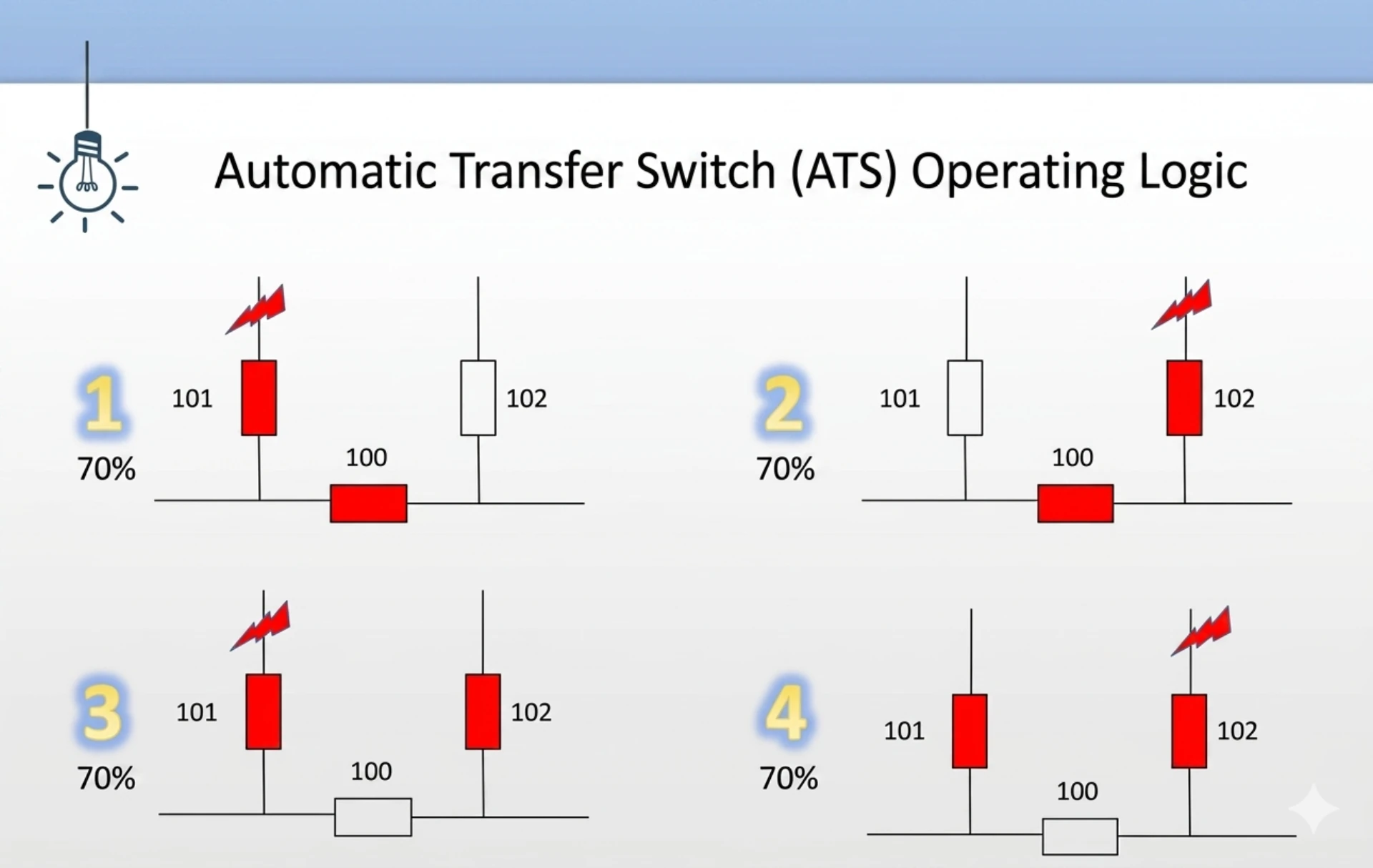
The logic of BZT rests on one sequence, break first then close. The two feeders are never connected at the same time, so the device needs no synchronism check and no phase-angle comparison. That is why the scheme is cheap, and why the bus goes dark for a moment.
Starting criteria: three-phase loss of voltage on the working busbar, together with no current in the working supply. The device holds a short confirmation delay before it acts, so a voltage dip caused by a motor starting elsewhere on the site does not start a transfer. One phase losing voltage is not enough to trip.
Operation process: after the delay, the device trips the working power switch first. Only when that switch is confirmed open does it issue the close command to the standby breaker. The open-state check on the working breaker is what stops a concurrent close if the upstream source was already lost.
What it costs: the whole sequence runs in hundreds of milliseconds to seconds, not in tens. By the time the standby breaker closes, the busbar voltage has almost gone and the motors have slowed.
Closing the standby source is then the same as starting every motor on that bus together. That group start pulls 4 to 7 times rated current, and if the standby feeder, transformer or breaker was not sized for it, the standby overload protection clears the transfer and the load stays dark.
The bus goes dark. That is the price.
Principle of Fast Transfer Device
The fast device takes the opposite route. Instead of waiting for the bus to die, it begins preparing for the transfer the moment it sees the fault. It uses something the conventional BZT scheme throws away: the motors themselves.
While the working breaker is open, the rotating motors on that bus act as generators and feed the bus back. That voltage is the residual voltage, and it decays as the motors slow.
The motors are still feeding the bus.
Starting criteria: loss of busbar voltage, plus predictive criteria such as protection initiation, reverse power initiation, or a sampled drop on the working line. Those signals appear before the breaker opens, which gives the device a head start that the conventional scheme never gets.
Operation process: the device trips the working switch, then tracks the residual voltage against the standby source in real time, watching frequency difference, phase difference and voltage difference. When all three fall inside the withstand window, it issues the close command.
- Fast transfer: closes while the phase difference between residual voltage and standby power is still small, under about 20 degrees. Almost no shock reaches the motor, and this is the mode the device aims at.
- Synchronisation capture transfer: misses that window, then predicts the instant when the phase difference comes back around zero and closes there.
- Residual voltage transfer: falls back to conventional BZT behaviour, closing once residual voltage has decayed to a safe value, roughly 20 percent to 40 percent of rated. It works. The load still feels the restart.
What sets the window: the motor withstand criteria. A motor tolerates a little slip and a little voltage dip. It does not tolerate a large phase difference at the instant the breaker closes, because that difference throws equivalent volts across the stator winding and swings the shaft torque with it. So the device does not pick a fixed time. It takes the first instant at which all three differences sit inside the withstand band.
That instant moves with the load.
Fast transfer suits switching of two operating modes.
The transfer logic is the same in both. What changes is where the standby source sits in the single line.
- Single bus configuration: one running section, one standby incomer, and the fast transfer device trips the running incomer and closes the standby one.
- Single bus with a sectionaliser: two sections of the same bus joined by a bus coupler, so the device can restore the lost section from the healthy half.
- Two-section bus on two transformers: the standby source is the other transformer, and the device has to check the coupler state before it closes the incomer.
- Plant auxiliary bus at 6 kV to 35 kV: the standby transformer is usually on the same site feeder chain, so the initiation comes from the auxiliary protection rather than from the bus voltage alone.
Backup Auto Switch (BZT) Product Introduction
The static automatic bus transfer switch is the cabinet or the panel that executes that sequence on behalf of the incoming feeder. It carries the logic, the contact outputs to the two breakers, and the measurement of both sources in one enclosure.
Functions and Features of Static Automatic Bus Transfer Switch
Main functions: automatic switching of the standby source. The two common logics are incoming-line backup auto transfer, which waits on the working incomer, and section backup auto transfer through the bus coupler, which waits on one half of the bus.
- Fixed logic: the operating logic follows a typical primary wiring scheme, which makes it easy to adapt to an existing single line.
- Integrated design: the device combines protection, measurement and control in one unit, and it speaks IEC 61850 as well as the older serial protocols.
- Charge and discharge logic: condition checks on both breakers before each command, so only one valid operation happens under correct working conditions.
One phase is not enough to start a transfer.
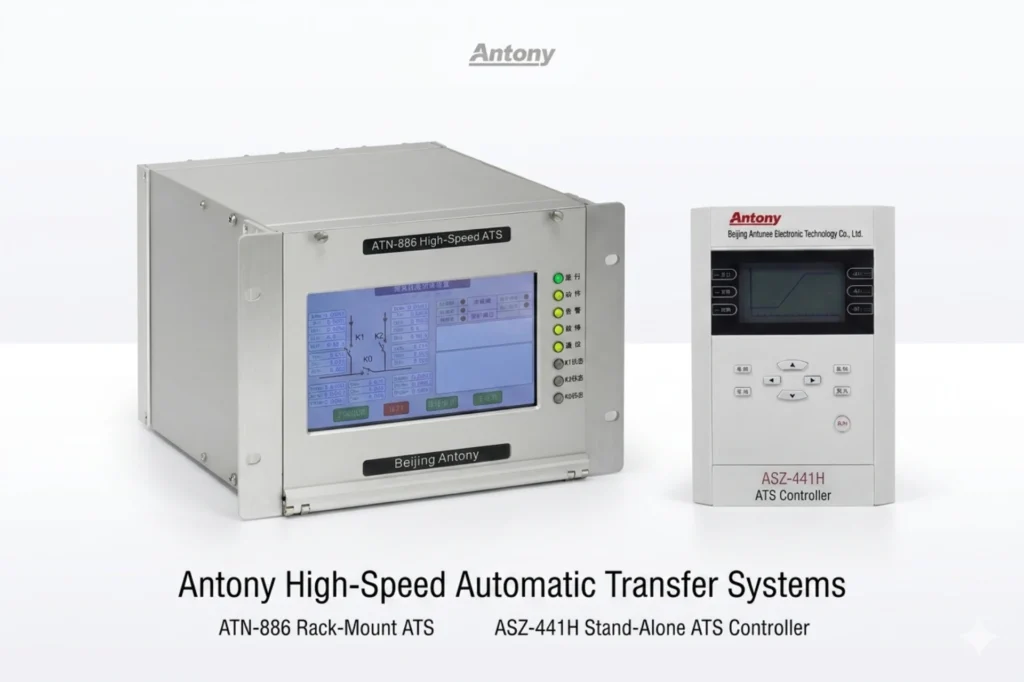
The conditions worth checking on the drawing are the ones that cause the nuisance trips in service. Both breakers must be in the remote position before the device acts. The coupler must be verified open when the working incomer is out of service, or the transfer restores load through the wrong path. And the standby source has to be proven healthy, transformer temperature and breaker position included, before the close command is issued. On a low-voltage installation the switch controller is often combined with the ATS unit itself, as in the ASZ-526H low voltage ATS controller.
Application Scenarios
This is where the backup auto switch is the right answer, and where it is not. The device belongs in installations that can absorb a transfer of 1 s or more without losing the load, and most automatic transfer applications sit in that band.
- Power incoming cabinets in ordinary factories and commercial buildings.
- Auxiliary loads that tolerate a voltage sag and a momentary drop in motor speed, such as lighting, space heating and general socket circuits.
- Sites where the standby is a generator, and the generator itself needs time to reach voltage before the load is transferred onto it.
Gensets need their own start delay.
Pair the switch with an emergency generator panel where the standby source is a genset, because the panel owns the start sequence and the device owns the transfer. The handover point between them is the generator closing contact, and that contact has to be wired into the transfer logic rather than into a hardwired interlock.
Fast Transfer Device Product Introduction
Functions and Features
Main functions: fast transfer under fault conditions, plus manual bidirectional transfer in normal operation, transfer on a protection trip that turns out to be a false one, and transfer on abnormal voltage or frequency.
- Predictive algorithm: the synchronisation capture algorithm tracks the rate at which the phase difference is moving, not just its present value, which raises the share of transfers that land in the fast window.
- Fault identification: the device separates a genuine bus fault from a voltage dip caused by a large motor starting, and refuses to transfer on the second one. Wrong transfers are what damage the standby equipment.
- Three switching sequences: parallel transfer, series transfer and simultaneous transfer, covering the different single-line arrangements.
The three sequences differ in what the bus sees while the breaker is travelling. Parallel transfer closes the standby breaker before it opens the working one, so the bus is momentarily fed from both and the transfer is the smoothest of the three. Series transfer opens first and closes on the dead bus, which is the same physics as the BZT scheme but with a much shorter gap. Simultaneous transfer is the usual choice on auxiliary systems where the breakers are close together and both can move at once.
Application Scenarios
Fast transfer earns its cost where a millisecond counts. Those are the sites with a large population of high-voltage motors already turning when the fault hits.
- High-voltage auxiliary systems of power plants at 6 kV, 10 kV and 35 kV.
- Continuous process industries: oil and gas, petrochemical, metallurgy, pulp and paper, and cement.
- Any process with an interlock that trips the whole line on loss of an auxiliary bus, so one failed fan takes the reactor down with it.
The counter-argument is real. Fast transfer needs both sources measurable, enough current transformers and voltage transformers to see them, and a breaker that can close on a synchronised residual voltage without bouncing. Older draw-out breakers with slow mechanism travel will not hold the 100 ms target however good the algorithm is.
Retrofitting onto those breakers is usually the reason to keep the BZT device as the second layer.
700 ms is a shutdown there.
Conclusion
A backup auto switch is the cheaper device and the one that leaves the bus dark for about a second. Fast transfer costs more, needs more instrumentation, and closes while the motors are still turning. Most sites that had only the conventional scheme are fine with it. The ones that are not are the plants where a transfer of 700 ms means a shutdown.
Two checks settle the choice before a budget is discussed. Count the high-voltage motors that would restart together on the standby source; above a few dozen, the inrush is the deciding number.
Then look at the standby breaker and transformer, because if either cannot carry that inrush the BZT scheme is not a saving but a false start.
Where the process genuinely cannot wait, the common arrangement is both devices in series, fast transfer in front and the BZT device behind it as the last layer.
Sizes and times above come from the transfer logic described above. Before an order goes out, confirm the breaker travel time and the standby short-circuit rating with the switchgear maker, since those two numbers decide whether the quoted transfer time is reachable.
Frequently Asked Questions
What is the difference between a backup auto switch and a fast transfer device?
The BZT device waits for the bus to collapse and then closes the standby source, which restarts every motor on the bus at once. The fast device watches the residual voltage the motors are still feeding and closes inside the window where the phase difference is small, usually within 100 ms. The first is cheap and slow, the second costs more and keeps the process running.
How long does a BZT transfer take?
Between 700 ms and 1 s in the common arrangement, and longer where the confirmation delay or the breaker travel time is generous. Most of that is the delay spent proving the voltage is really gone, not the switching itself. Where the standby is a generator, add the time the genset needs to reach voltage.
Can fast transfer replace an ATS?
Different machine.
Not for the low-voltage mains changeover, where the two sources are an incoming feeder and a genset on the same LV board. It is the right device for 6 kV, 10 kV and 35 kV auxiliary buses with rotating machines on them. On LV changeover the equivalent product is the high speed ATS, which is a different machine from a bus transfer relay.
What standby source size does the BZT require?
Large enough to carry the group start. If the whole bus comes back together, the standby transformer, feeder and breaker see the combined inrush of every motor, which runs at 4 to 7 times rated current for the length of the starting period. Size for that or the standby overload protection will clear the transfer.
Why did the transfer not happen when the main broke?
Three causes cover almost every case. The initiating criteria were never both true at once, usually because current was still flowing in the working supply. The standby source was not proven healthy, so the close command was held back. Or the working breaker never returned its open position to the device, and the transfer waits on that signal forever.
Which standard covers automatic transfer switching systems?
IEC 60947-6-1 for an automatic transfer switching system at low voltage. On the North American side, IEEE 446 and NFPA 110 cover emergency and standby power systems, and UL 1008 covers the transfer switch equipment itself. Confirm the current edition with the issuing body before a specification is issued, and ask for the type test report against it.
Technical Reference
| Standard | Scope | Use For |
|---|---|---|
| IEC 60947-6-1 | Automatic transfer switching systems (ATSE) | Operating sequence, test duty and the specification point for a low-voltage ATSE |
| IEEE 446 | Emergency and standby power systems (recommended practice) | Transfer timing, source rating and the North American project basis |
| NFPA 110 | Emergency and standby power systems (performance category) | What a class and level installation has to transfer within |
| UL 1008 | Transfer switch equipment | Type approval of the switch unit itself |
| IEC 61850 | Substation communication | Carrying the transfer command and the event records onto the station LAN |
| IEC 60255 series | Measuring relays and protection equipment | Type tests and the response times printed on a datasheet |
The transfer times and inrush figures quoted here follow the logic described above and the switchgear maker type test. Breaker travel time and standby short-circuit rating are site specific, so confirm both with the assembly manufacturer before the specification is frozen.
Related Reading



About Author

Hello, I'm Leno Zhang. I have 15 years of experience in the power relay protection industry with extensive pre-sales and after-sales project experience. Our company specializes in various complete sets of relay protection and automation equipment. I can assist customers in solving all practical on-site project challenges and provide optimal integrated solutions.
Tell Us Your Requirement
High Quality
Stable performance, reliable design, ensuring safe operation for power system protection and grid stability.
Fast Delivery
Timely delivery to support your urgent orders and project schedules efficiently and professionally at any time.
Best Warranty
Professional Warranty: Reliable after-sales support for stable relay protection and long-term customer satisfaction.