

-
Leon Zhang sales consultant
-
Email: zxl635973785@gmail.com
-
Phone/WhatsApp: +86 13655813266
How Does a Digital Fault Recorder Work?
A digital fault recorder (DFR) continuously monitors electrical signals from power systems in substations, power plants, and industrial grid facilities. When predefined abnormal electrical conditions or trigger events occur, the device captures high-precision waveform data covering the pre-fault, in-fault, and post-fault stages. The recorded voltage, current, frequency, breaker status, and protection relay signals enable power engineers to accurately reconstruct fault sequences, locate disturbances, and verify protection system performance.
This article, themed on Working Principles of the Digital Fault Recorder, comprehensively analyzes the working principles of the Digital Fault Recorder (DFR), and elaborates on key links ranging from signal acquisition, analog‑to‑digital conversion, cyclic buffering, trigger detection, waveform recording, data storage to post‑fault analysis. It helps power system and EPC engineers understand how DFRs capture and record power grid faults under actual on‑site operating conditions.
What Is a Digital Fault Recorder?
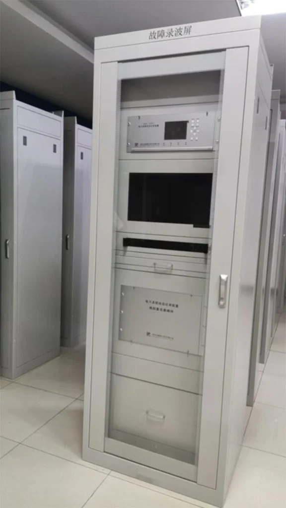
A digital fault recorder (DFR) is a dedicated power system monitoring device designed for disturbance capture and fault documentation. Unlike general power monitoring equipment, it focuses on high-speed, high-accuracy recording of transient grid disturbances rather than routine power data statistics. It operates passively alongside power system protection devices without interfering with normal grid operation or protection tripping logic.
Click here to learn more about fault recording panels
What Does a Digital Fault Recorder Monitor?
DFRs collect real-time analog and digital signals from grid primary and secondary equipment to build a comprehensive data foundation for fault analysis. Typical monitoring signals and their functions are listed in the table below:
| Signal Type | Typical Source | Core Purpose |
|---|---|---|
| Phase/Residual Current | Current Transformer (CT) | Detect fault current magnitude, surge characteristics, and residual ground current for ground fault analysis |
| Phase Voltage | Voltage Transformer (VT/PT) | Analyze voltage sag, swell, outage, and unbalance disturbances during grid faults |
| Grid Frequency | DFR real-time algorithm calculation | Monitor frequency deviation and rate-of-change frequency (ROCOF) for grid stability assessment |
| Breaker Status | Circuit breaker auxiliary contacts | Record breaker closing/opening actions and fault clearing timing |
| Protection Trip Signals | Protection relay digital outputs | Correlate protection action logic with actual grid fault events |
| Digital Status Signals | Substation secondary control loops | Track auxiliary equipment status changes during disturbances |
Working Principles of the Digital Fault Recorder
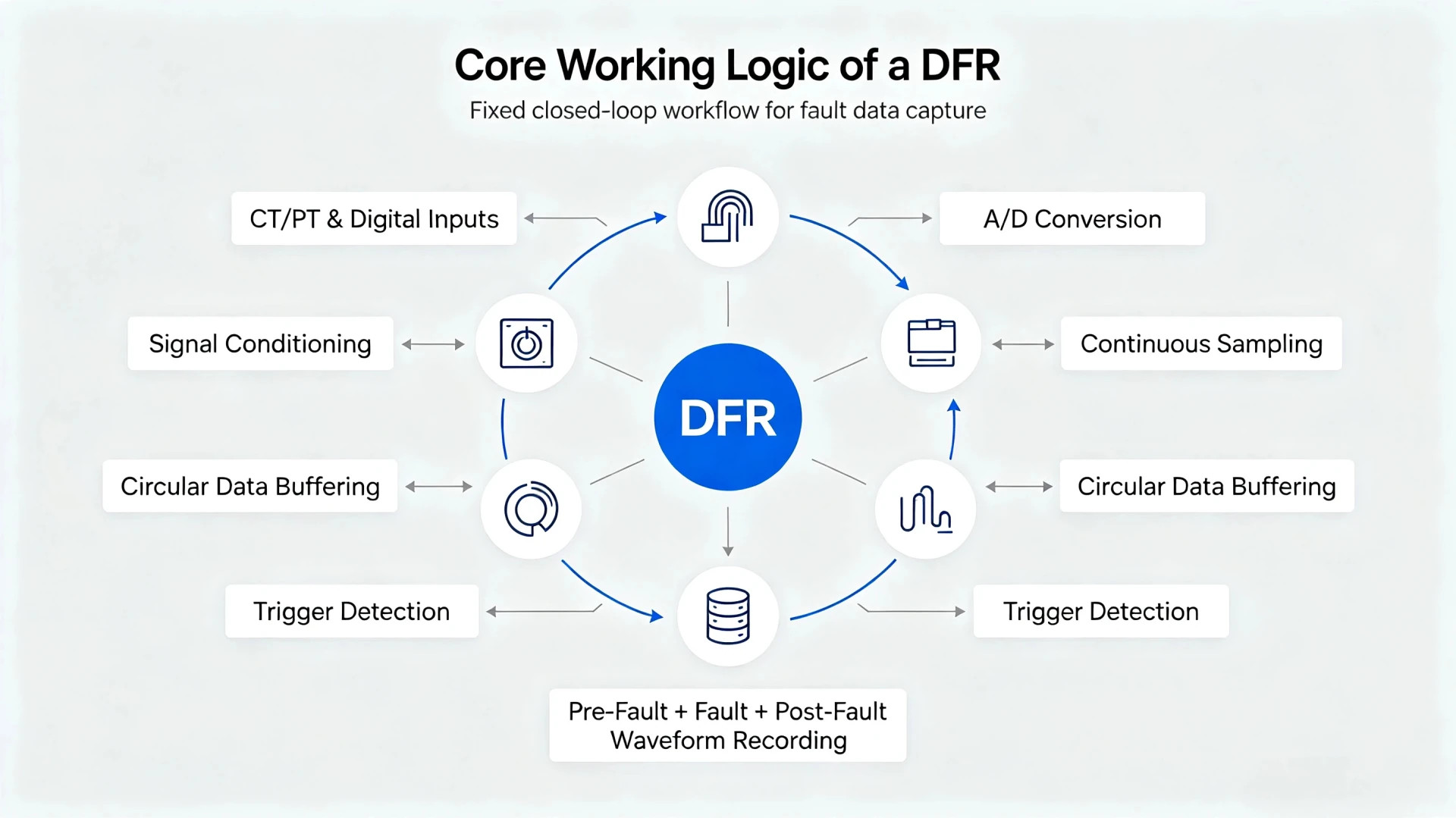
The core working logic of a DFR follows a fixed closed-loop workflow, supporting full-cycle fault data capture. The standard operating sequence is as follows:
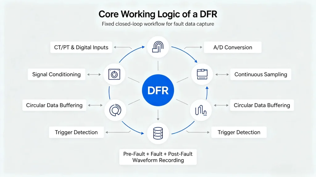
CT/PT & Digital Inputs → Signal Conditioning → A/D Conversion → Continuous Sampling → Circular Data Buffering → Trigger Detection → Pre-Fault + Fault + Post-Fault Waveform Recording → Local/Cloud Data Storage → Post-Fault Professional Analysis
The detailed breakdown of each core working step is explained below:
1. Continuous Real-Time Signal Acquisition
A DFR operates 24/7 to continuously acquire signal data from grid secondary devices, including CTs, VTs/PTs, circuit breaker auxiliary contacts, and protection relays. It does not start working only after a fault occurs. This persistent monitoring is the core prerequisite for capturing complete fault data.
The key value of continuous acquisition is to retain the complete electrical state of the power system immediately before fault inception, which is critical for engineers to trace the root cause of grid disturbances.
2. Analog Signal Conditioning and A/D Conversion
All current and voltage signals output by CTs and VTs are analog signals that cannot be directly identified by digital processing chips. The DFR first performs signal conditioning, including filtering high-frequency interference, amplifying weak signals, and limiting overvoltage signals, to eliminate field electromagnetic interference and ensure data accuracy.
After conditioning, the built-in high-speed ADC (Analog-to-Digital Converter) converts continuous analog waveforms into discrete digital sampling values. Standard grid DFRs adopt industry-grade sampling rates to ensure the restoration of transient fault characteristics without distortion.
3. Continuous Sampling and Circular Buffer Storage
Most low-end monitoring devices only record data after a fault is triggered, resulting in the loss of pre-fault state data. Professional DFRs adopt a circular buffer mechanism to solve this problem.
The DFR continuously writes real-time digital sampling data into a fixed-capacity memory buffer. When the buffer is full, new data automatically overwrites the oldest historical data, forming a cyclic real-time data cache. Once a fault trigger condition is met, the system instantly locks the buffer data and stops overwriting, permanently retaining all waveform data before the fault occurs.
Why pre-fault recording is essential: Power system faults are often caused by gradual system state changes rather than sudden failures. Pre-fault data allows engineers to analyze initial system operating conditions, fault evolution processes, and whether abnormal states existed before protection actions.
How Does a DFR Detect a Fault?
It is critical to clarify that DFRs do not actively “judge and eliminate faults” like protection relays. Instead, they trigger recording actions based on pre-configured threshold logic. The core function of DFRs is disturbance recording, not system protection and tripping.
What Triggers a Digital Fault Recorder?
DFR supports multiple industry-standard trigger conditions, covering most common power system disturbances. All trigger thresholds are configurable according to substation voltage level, grid type, and operational requirements:
- Overcurrent threshold exceeding
- Overvoltage and undervoltage deviation
- Grid frequency deviation and ROCOF abnormality
- Protection relay trip signal input
- Circuit breaker status switching action
- External remote trigger signal
- User-defined customized fault logic triggers
Protection Relay Trigger vs. DFR Trigger
Many field engineers confuse the functional logic of DFRs and protection relays. The core functional differences in trigger and operating mechanisms are clarified in the table below:
| Dimension | Protection Relay | Digital Fault Recorder |
|---|---|---|
| Core Purpose | Realize power system protection and isolate fault points | Record full fault process data for post-event analysis |
| Output Action | Sends trip commands to breakers to cut off faults | No tripping action; only locks and stores waveform data |
| Data Focus | Focus on fault judgment and rapid response | Focus on pre-fault, in-fault and post-fault full-process waveform restoration |
| Operating Logic | Strict national standard protection fixed values | Flexible customizable recording trigger thresholds |
What Happens When a Fault Occurs? (Full Timeline)
A complete DFR fault recording process follows a strict time sequence, realizing full-process coverage of grid disturbances:
1. Before the Fault (Steady-State Monitoring)
The DFR maintains continuous signal sampling and circular buffer storage, recording real-time steady-state voltage, current, frequency, and equipment status signals to retain normal system operating baseline data.
2. Fault Inception
Grid abnormal disturbances occur, including transmission line short circuits, ground faults, transformer abnormal operation, generator parameter fluctuations, and other typical faults. Electrical parameters break steady-state values and reach the DFR preset trigger threshold.
3. Trigger Event Activation
The DFR system detects threshold deviation, immediately locks the circular buffer data, and officially activates the fault recording mode to stop data overwriting.
4. Post-Fault Continuous Recording
After fault triggering, the DFR continues to record for a set duration to capture subsequent key events: protection relay action, circuit breaker opening, fault current interruption, voltage recovery, and grid system stabilization.
5. Complete Data Storage
After the post-fault recording cycle ends, the DFR automatically sorts and packages pre-fault, in-fault, and post-fault data into standard fault record files and stores them locally for subsequent query, download, and analysis.
What Does a Digital Fault Recorder Record?
DFR recorded data is divided into three categories, providing multi-dimensional data support for comprehensive fault diagnosis:
Analog Data
High-speed continuous waveforms of three-phase current, three-phase voltage, residual current, and real-time grid frequency, which can accurately restore transient fluctuation characteristics during faults.
Digital Data
Switching state of circuit breakers, action signals of protection relays, auxiliary equipment alarm status, and secondary loop switching signals, used to sort out the sequence of equipment actions during faults.
Calculated Data
Secondary calculation data based on original sampling waveforms, including RMS values of voltage and current, phase angle parameters, positive/negative/zero sequence components, and fault duration parameters.
How Does Digital Fault Recording Help Analyze a Fault?
The core value of DFR lies in converting vague fault phenomena into accurate, data-supported conclusions, helping engineers solve core pain points in field fault disposal:
Identify Accurate Fault Inception Time
High-precision sampling waveforms can pinpoint the exact moment electrical parameters start to mutate, solving the problem of inaccurate fault timing in manual field records.
Verify Protection Relay Operating Validity
By comparing fault current waveforms and relay trip signal timestamps, engineers can judge whether the protection device acts in accordance with standard logic, and identify misoperation, refusal operation, or delayed action problems.
Confirm Circuit Breaker Operating Status
Breaker status recording data accurately reflects the opening and closing time of the switch, verifying whether the breaker successfully isolates the fault point.
Calculate Accurate Fault Duration
By calculating the time difference between fault parameter mutation inception and fault current complete interruption, the actual fault duration is obtained, providing a basis for grid equipment loss assessment.
DFR Working Process Example: Three-Phase Transmission Line Fault
The following actual field case intuitively demonstrates the complete DFR operating workflow:
Fault Scenario: Instant three-phase short-circuit fault on a 110kV transmission line
- The DFR continuously samples and buffers steady-state voltage and current data of the transmission line
- Three-phase short circuit occurs, line current rises sharply and voltage drops rapidly, reaching the DFR overcurrent and undervoltage trigger thresholds
- DFR locks pre-fault steady-state data and starts official fault recording
- Substation protection relay detects the fault and outputs a trip signal
- Circuit breaker receives the signal and opens to isolate the fault point, fault current disappears
- DFR continues post-fault recording until grid voltage and frequency return to steady state
- The device automatically stores the complete fault waveform and event sequence file
- Field engineers download data to analyze fault cause, protection action rationality, and grid recovery status
DFR vs. Protection Relay: Core Differences
To avoid functional misunderstanding in EPC project design and substation operation, the core differences between DFR and protection relays are summarized as follows:
| Feature | DFR | Protection Relay |
|---|---|---|
| Core Function | Disturbance recording and post-fault analysis | Real-time fault isolation and system protection |
| Full Waveform Recording | 24/7 continuous sampling and recording | Only record key event points, no complete waveforms |
| Pre-Fault Data Retention | Complete pre-fault waveform data retained | Not supported |
| Breaker Tripping | No tripping output function | Core tripping control function |
| Post-Fault Analysis Capability | Professional full-process waveform analysis | Only simple event logging |
Core Conclusion: A DFR records what happened in the power system during disturbances; a protection relay acts immediately to protect the power system from damage. The two devices cooperate complementarily in substation operation.
What Happens to DFR Data After Recording?
DFR fault data forms a closed-loop application process after recording, supporting full-cycle grid operation optimization:
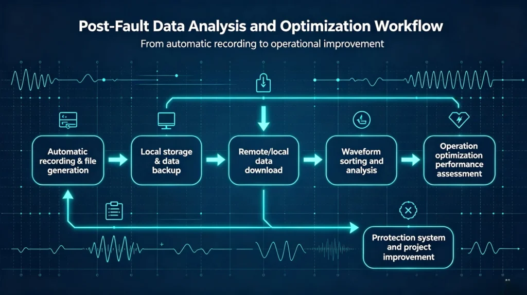
Automatic recording & file generation → Local storage & data backup → Remote/local data download → Waveform sorting and analysis → Fault root cause diagnosis → Protection system performance assessment → Operation optimization and project improvement
Engineers focus on analyzing four core data dimensions: fault occurrence sequence, protection response timeliness, breaker operation reliability, and grid system recovery efficiency, to eliminate hidden dangers and optimize substation operation strategies.
What Factors Affect DFR Recording Performance?
The accuracy and integrity of DFR fault recording are determined by multiple core parameters, which are key indicators for EPC project selection and equipment commissioning:
Sampling Rate
Higher sampling rates capture more detailed transient waveform characteristics, effectively recording high-frequency transient faults and instantaneous parameter mutations that low-sampling devices cannot identify, ensuring no missing of subtle fault features.
Analog & Digital Channel Quantity
The number of analog channels determines the maximum number of voltage and current signals that can be monitored simultaneously; digital channels support synchronous recording of more protection and breaker status signals, suitable for large substations and multi-branch power plants.
Trigger Settings
Unreasonable trigger thresholds will cause two common problems: overly strict settings lead to missing minor disturbance records, while overly loose settings generate a large number of invalid recordings and occupy storage space. Flexible customizable trigger logic ensures effective and accurate recording.
Recording Duration Configuration
Reasonable configuration of pre-fault recording time, fault duration, and post-fault stabilization time ensures complete coverage of the entire fault evolution process, avoiding incomplete data capture.
How to Interpret a DFR Waveform
Standard DFR waveform analysis follows a unified industry process, enabling engineers to quickly complete fault diagnosis:
- Locate the exact fault inception point via waveform parameter mutation
- Analyze voltage and current fluctuation ranges and mutation characteristics
- Check the action time and logic of protection relay signals
- Verify the opening/closing status and action timeliness of circuit breakers
- Calculate fault clearing time and evaluate protection efficiency
- Observe post-fault waveform recovery to judge grid stability
Common Industrial Applications of DFRs
DFRs are standard auxiliary monitoring equipment for medium and high-voltage power systems, widely used in scenarios requiring high-reliability fault monitoring and analysis:
- High/medium-voltage transmission and distribution substations
- Thermal power, hydropower, and new energy power plants
- Large industrial enterprise self-owned power systems
- Grid dispatching and disturbance monitoring systems
- EPC power project supporting monitoring systems
Click to learn more about substation fault recording.
FAQs About Digital Fault Recorders
1. How does a DFR work in simple terms?
A DFR continuously samples power system electrical and status signals, caches data in real time, triggers recording when meeting preset fault thresholds, and stores full-process pre-fault, in-fault and post-fault data for engineers to analyze grid disturbances.
2. Does a DFR record data continuously?
DFRs perform continuous sampling and cyclic buffering in real time, but only generate and store complete independent fault files after trigger activation, avoiding massive invalid steady-state data storage.
3. Can a DFR actively detect and eliminate faults?
No. DFRs only monitor and record fault data and do not have fault judgment and isolation functions. Grid fault elimination is completed by protection relays and circuit breakers.
4. What is pre-fault recording and why is it important?
Pre-fault recording refers to the retention of steady-state waveform data before fault occurrence. It helps engineers analyze the initial state of the system, trace the root cause of fault evolution, and verify the rationality of protection action logic.
5. What is the difference between a DFR and a common event recorder?
Event recorders only record discrete equipment status events, while DFRs record continuous high-precision analog waveforms and synchronous digital events, supporting quantitative fault analysis rather than simple event logging.
Conclusion
A digital fault recorder realizes full-cycle power system disturbance monitoring through continuous signal acquisition, analog-to-digital conversion, cyclic data buffering, threshold-based trigger detection, and full-process waveform storage. By synchronously recording voltage and current waveforms, relay protection actions, and breaker operating status, DFRs enable power and EPC engineers to accurately reconstruct fault sequences, verify protection system performance, and locate disturbance root causes.
For substations, power plants, and industrial power projects pursuing high grid operation reliability, a standard DFR is an essential device for post-fault investigation, operation optimization, and project acceptance verification.
Technical Reference Sources
- IEC 61086:2004 Standard for Power System Fault Recording Equipment
- IEEE C37.111: Standard for Synchrophasor Measurements for Power Systems
- GB/T 14598.303-2016 Technical Specification for Power System Fault Recorders
- International Council on Large Electric Systems (CIGRE) Working Group B4.23 Technical Report on Grid Disturbance Monitoring



About Author

Hello, I'm Leno Zhang. I have 15 years of experience in the power relay protection industry with extensive pre-sales and after-sales project experience. Our company specializes in various complete sets of relay protection and automation equipment. I can assist customers in solving all practical on-site project challenges and provide optimal integrated solutions.
Tell Us Your Requirement
High Quality
Stable performance, reliable design, ensuring safe operation for power system protection and grid stability.
Fast Delivery
Timely delivery to support your urgent orders and project schedules efficiently and professionally at any time.
Best Warranty
Professional Warranty: Reliable after-sales support for stable relay protection and long-term customer satisfaction.