

-
Leon Zhang sales consultant
-
Email: zxl635973785@gmail.com
-
Phone/WhatsApp: +86 13655813266
Numerical Overcurrent Protection Relay
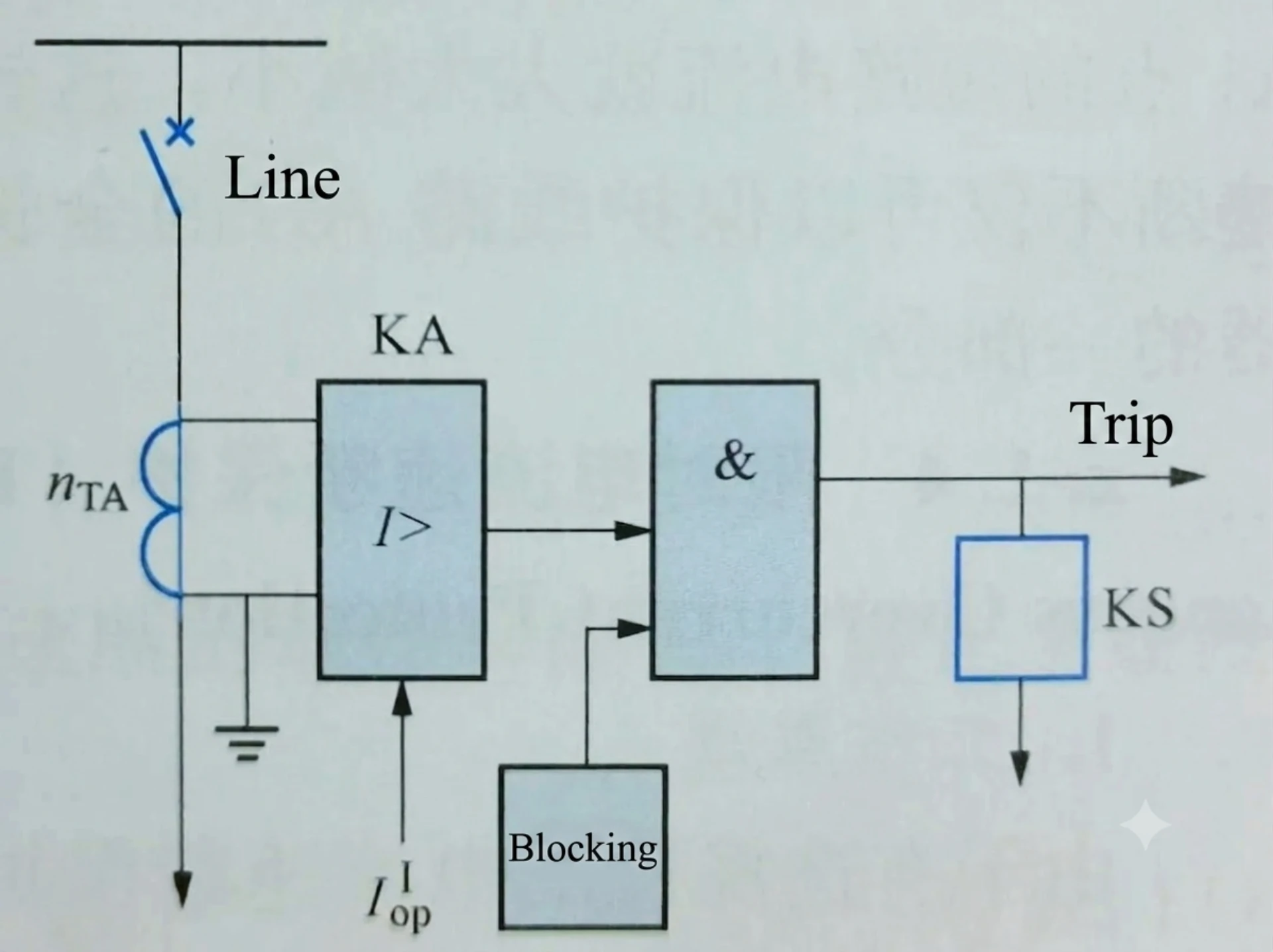
Numerical overcurrent protection relays are microprocessor-based protection devices that combine current measurement, digital protection algorithms, fault recording, communication and multiple protection functions in a single device. They are widely used in medium-voltage distribution systems, substations, industrial power systems and renewable energy applications.
What Is a Numerical Overcurrent Protection Relay?
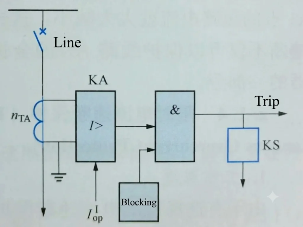
A numerical overcurrent protection relay is a microprocessor-based protection device that integrates current measurement, digital protection algorithms, fault recording, communication, and multiple protection functions into a single unit. Unlike traditional electromechanical or static relays, numerical relays use digital signal processing to provide accurate, flexible, and programmable protection for medium-voltage distribution systems, substations, industrial power systems, and renewable energy applications.
The following sections explain how a numerical overcurrent protection relay works — from signal acquisition to trip output and communication.
Analog Signal Acquisition
What it does:
The numerical overcurrent relay receives analog current signals from Current Transformers (CTs) . These signals represent the actual current flowing through the protected feeder — stepped down to safe secondary values such as 5A or 1A.
Why it matters:
Accurate signal acquisition is the foundation of all protection functions. If the relay does not receive a true representation of the system current, all subsequent calculations and decisions will be incorrect.
Key components:
- CT inputs (1A / 5A)
- Anti-aliasing filters to remove high-frequency noise
- Voltage inputs (if voltage protection or directional functions are required)
A/D Conversion
What it does:
The analog signals from the CTs are passed through an Analog-to-Digital Converter (ADC) . The ADC samples the analog signals at a high frequency (typically 32–64 samples per cycle) and converts them into digital values that the microprocessor can process.
Why it matters:
The microprocessor cannot process analog signals directly. A/D conversion is the bridge between the physical world (current flowing in the power system) and the digital world (calculations performed by the relay).
Key specifications:
- Sampling rate — typically 32 to 64 samples per power cycle
- Resolution — 12-bit to 16-bit for accurate measurement
- Sampling synchronized to the system frequency (50/60 Hz)
Microprocessor Processing
What it does:
The microprocessor (CPU) receives the digital current samples and performs real-time calculations:
- RMS (Root Mean Square) — Calculates the effective current value
- Fundamental component extraction — Filters out harmonics and DC offset
- Frequency tracking — Adapts to system frequency variations
- Fourier analysis — Extracts the fundamental frequency component for accurate protection decisions
Why it matters:
The microprocessor is the “brain” of the relay. It processes raw data into meaningful values that the protection algorithms can use.
Protection Logic
What it does:
The microprocessor continuously compares the calculated current values against user-defined protection settings:
- Pickup current — The threshold that triggers protection
- Time curve — IDMT or Definite Time characteristics (IEC or IEEE curves)
- Time multiplier — Adjusts the operating speed
When the measured current exceeds the pickup setting, the relay starts timing according to the selected curve. If the current remains above pickup for the calculated time duration, the relay decides that a fault has occurred.
Common protection functions:
| Function | ANSI Code | Description |
|---|---|---|
| Phase Overcurrent | 50/51 | Detects phase-to-phase and three-phase faults |
| Earth Fault | 50N/51N | Detects phase-to-ground faults |
| Directional Overcurrent | 67 | Detects fault direction |
| Negative Sequence | 46 | Detects unbalance and phase loss |
| Thermal Protection | 49 | Protects against overload heating |
Why it matters:
The protection logic is where the digital overcurrent protection relay makes the critical decision — whether to trip or not. Accuracy and speed at this stage determine how well the relay protects the system.
Trip Output
What it does:
When the protection logic determines that a fault exists, the digital overcurrent relay issues a trip command through its output contacts. This command energizes the circuit breaker’s trip coil, causing the breaker to open and isolate the fault.
Key specifications:
- Output contacts — typically Form-C (N/O and N/C)
- Contact rating — capable of handling the breaker’s trip coil current
- Trip circuit supervision — continuous monitoring of the trip circuit health
Why it matters:
The trip output is the relay’s final action. No matter how accurate the measurement or how fast the algorithm, the relay must deliver a reliable trip signal to the breaker to clear the fault.
Event and Fault Recording
What it does:
Numerical relays continuously record operational data. When a fault occurs, the relay captures:
- Event records — Time-stamped log of relay operations (pickup, trip, reset)
- Fault records — Current and voltage values at the time of the fault
- Oscillography — Waveform capture showing current and voltage signals before, during, and after the fault
Why it matters:
Event and fault recording is essential for post-fault analysis:
- Verify that the relay operated correctly
- Determine the cause of the fault
- Analyze system behavior during the fault
- Optimize protection settings based on actual fault data
Key features:
- Sequence of Events (SOE) — records all digital state changes with millisecond accuracy
- Disturbance records — waveform data for detailed analysis
- Non-volatile memory — data is retained even if relay loses power
Communication
What it does:
Numerical relays include communication capabilities to interface with SCADA systems, control centers, and other IEDs. This enables:
- Remote monitoring — view current values and relay status from a control center
- Remote control — issue trip/close commands or change settings remotely
- Data retrieval — download fault records and oscillography files
- System integration — share data with other protection and automation devices
Common communication protocols:
| Protocol | Application |
|---|---|
| Modbus RTU/TCP | Simple, widely supported for SCADA integration |
| IEC 61850 | Advanced substation automation with GOOSE messaging |
| IEC 60870-5-103/104 | Utility telecontrol standard |
| DNP3 | Common in North American utilities |
Why it matters:
Communication transforms a standalone relay into a connected asset — enabling remote visibility, control, and integration with the broader power system automation architecture.
Numerical Relay vs Electromechanical Relay
| Feature | Numerical Relay | Electromechanical Relay |
|---|---|---|
| Processing | Digital | Electromechanical |
| Multiple Functions | High | Limited |
| Event Recording | Yes | Limited |
| Communication | Yes | Limited |
| Setting | Software / Digital | Mechanical |
| Self-Diagnostics | Available | Limited |
| SCADA Integration | Easy | Limited |
| Maintenance | Lower | Higher |
Protection Functions Integrated in Numerical Overcurrent Relays
| ANSI | Function | Purpose |
|---|---|---|
| 50 | Instantaneous Overcurrent | Fast fault clearing |
| 51 | Time Overcurrent | Coordinated protection |
| 50N/51N | Earth Fault | Ground fault protection |
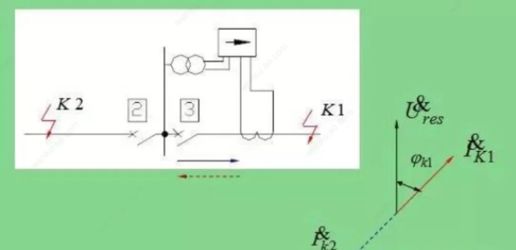
| 67 | Directional Overcurrent | Directional fault discrimination |
For detailed directional protection principles, see our Directional Overcurrent Protection Guide.
Numerical Relay Setting
Numerical relays provide digital parameters for pickup current, time-current curve, time multiplier and other protection functions. Actual settings should be calculated according to the system short-circuit study, CT ratio, load current and protection coordination requirements.
For detailed 50/51 setting calculations, see our Overcurrent Relay Setting Guide.
Communication and SCADA Integration
Modern numerical overcurrent protection relays are not standalone devices — they are integrated components of a digital substation automation system. Communication and SCADA integration enable remote monitoring, control, and data analysis, transforming a traditional protection relay into a smart, connected asset.
Key Communication Interfaces
Numerical relays support a range of physical interfaces to connect with substation networks:
- Ethernet — High-speed backbone for IEC 61850 and Modbus TCP communication
- RS485 — Serial communication for Modbus RTU and legacy device integration
- Fiber Optic — Noise-immune, long-distance communication for critical protection signals
- USB / Console Port — Local configuration and firmware updates
Supported Communication Protocols
| Protocol | Application |
|---|---|
| IEC 61850 | International standard for substation automation — supports GOOSE for high-speed peer-to-peer protection signaling, MMS for client-server communication, and full engineering interoperability |
| Modbus RTU / TCP | Simple, open protocol widely used for SCADA integration and data exchange with PLCs and HMIs |
| IEC 60870-5-103 | Utility telecontrol protocol for protection equipment communication |
| IEC 60870-5-104 | Network-accessible version of 103, enabling wide-area telecontrol over TCP/IP |
| DNP3 | Common in North American utilities, supporting both serial and IP-based communication |
SCADA Integration
SCADA integration allows the numerical relay to communicate seamlessly with the central control system, providing:
- Remote monitoring — Real-time access to current, voltage, power, frequency, and relay status from the control center
- Remote control — Open/close circuit breakers, enable/disable protection functions, or reset alarms without dispatching field personnel
- Remote setting — Adjust protection pickup values, time curves, and logic configurations remotely — eliminating the need for on-site visits for routine setting changes
- Event recording — Automatic upload of event logs and fault records to the SCADA system for analysis and reporting
- Oscillography retrieval — Remote download of waveform files for post-fault analysis and disturbance evaluation
Practical Benefits
- Reduced site visits — Remote monitoring and setting changes significantly reduce the need for on-site intervention
- Faster fault response — SCADA alarms immediately notify operators of protection operations, enabling rapid decision-making
- Better system visibility — Real-time data and event records provide a complete picture of system performance
- Improved protection coordination — Remote analysis of fault records allows engineers to fine-tune settings based on actual system behavior
How to Select a Numerical Overcurrent Protection Relay
Selecting the right numerical overcurrent protection relay requires a systematic approach. Below is a step-by-step selection guide covering the key technical parameters for EPC engineers, procurement specialists, and system integrators.
1. System Voltage
Common levels: 6kV, 10kV, 11kV, 20kV, 22kV, 33kV, 35kV
Why it matters: The microprocessor overcurrent relay must be compatible with the system voltage and corresponding VT ratios. Check that the relay supports your specific voltage level.
2. CT Input
| Rating | Application |
|---|---|
| 1A | European, Asian, and IEC-standard systems |
| 5A | North American and older installations |
Many relays support both 1A and 5A with selectable settings — ideal for retrofit projects.
3. Protection Functions
| Function | ANSI | When Required |
|---|---|---|
| Phase Overcurrent | 50/51 | Always required |
| Earth Fault | 50N/51N | Required for most systems |
| Directional Overcurrent | 67 | Looped networks, parallel feeders, multi-source systems |
| Directional Earth Fault | 67N | Grounded systems with multiple sources |
| Over/Undervoltage | 59/27 | Voltage-sensitive loads or generator interconnections |
| Negative Sequence | 46 | Motor-heavy loads or unbalanced systems |
| Breaker Failure | 50BF | Critical feeders requiring backup protection |
4. Communication
| Protocol | Application |
|---|---|
| IEC 61850 | Digital substations — supports GOOSE and MMS |
| Modbus RTU/TCP | Industrial SCADA integration |
| IEC 60870-5-103/104 | Utility telecontrol |
| DNP3 | North American utilities |
Physical interfaces: Ethernet (high-speed), RS485 (serial), Fiber Optic (long-distance)
5. I/O (Binary Input / Output)
| I/O Type | Function | Typical Count |
|---|---|---|
| Binary Inputs | Breaker status, external interlock, reset | 4–8 inputs |
| Binary Outputs | Trip commands, alarm signals | 4–8 outputs |
6. Event and Fault Recording
| Feature | Purpose |
|---|---|
| SOE (Sequence of Events) | Time-stamped record of relay operations |
| Fault Records | Current/voltage values at fault time |
| Oscillography | Waveform capture for detailed fault analysis |
Essential for post-fault analysis, verifying relay operation, and optimizing settings.
7. Installation
| Type | Application |
|---|---|
| Panel Mount | Control rooms, protection panels |
| Switchgear Mount | Compact switchgear, RMU |
| DIN Rail | LV/MV distribution panels |
Check: Panel cutout dimensions (e.g., 144×144mm, 96×96mm) and depth clearance.
Applications of Numerical Overcurrent Protection Relays
Numerical overcurrent protection relays are versatile devices deployed across a wide range of power system applications. Their flexibility, accuracy, and communication capabilities make them the preferred choice for protection schemes at all voltage levels.
Medium Voltage Distribution
Application: 6kV to 35kV distribution feeders in utility substations, industrial plants, and commercial facilities.
Key functions: 50/51, 50N/51N, 67/67N (for looped networks)
Why: Ensures selective fault clearing, minimizing outage areas.
Feeder Protection
Application: Overhead lines and underground cable feeders.
Key functions: 50/51, 50N/51N, 67 (for complex networks), 79 (for overhead lines)
Why: Programmable logic allows optimized settings for different feeder types.
Transformer Backup Protection
Application: Backup protection for power transformers when primary differential protection is not installed.
Key functions: 51, 51N, 49, 46
Why: Thermal modeling and flexible IDMT curves coordinate with transformer withstand curves.
Motor Protection
Application: Medium-voltage motors in industrial processes, pumping stations, and compressors.
Key functions: 50/51, 50N/51N, 46, 49 (thermal with memory)
Why: Thermal modeling and start-up supervision protect motors from overload and stall conditions.
Generator Backup Protection
Application: Backup protection for generators or second-zone protection on step-up feeders.
Key functions: 51, 51N, 46, 59/27
Why: Provides coordinated backup with precise timing and DCS/SCADA communication.
Power Plants
Application: Auxiliary power distribution within thermal, hydro, and nuclear plants.
Key functions: 50/51, 50N/51N, 67 (for multi-source systems), 59/27
Why: Self-diagnostics and event recording ensure rapid fault identification.
Industrial Facilities
Application: Steel mills, cement plants, chemical factories, automotive plants.
Key functions: 50/51, 50N/51N, 46, 59/27, 50BF (for critical feeders)
Why: Robust design handles high fault currents and harsh environments.
Renewable Energy Collector Systems
Application: Solar farms, wind parks, and BESS collector feeders.
Key functions: 50/51, 50N/51N, 67/67N (bidirectional flow), 59/27, 46
Why: Sensitive settings and flexible curves handle limited fault current from inverter-based sources.
FAQ
What is a numerical overcurrent protection relay?
It is a microprocessor-based intelligent protection device that monitors system overcurrent faults, realizes automatic alarm and tripping through digital sampling and algorithm judgment, and integrates multiple protection, measurement and communication functions.
What is the difference between 50 and 51 functions?
50 is instantaneous overcurrent protection for severe short-circuit faults with zero delay tripping; 51 is time-delayed inverse overcurrent protection for overload and general short-circuit faults, with adjustable delay and time curve to ensure protection coordination.
How do you set overcurrent relay settings?
Complete setting calculation based on system load current, short-circuit current, CT ratio and coordination margin, confirm pickup current, TMS and curve type, and verify protection selectivity and reliability through coordination study.
Where is a numerical relay used?
It is widely used in MV distribution substations, power plants, steel plants, petrochemical parks, mining power systems, and new energy power stations for feeder, transformer and motor overcurrent protection.
What communication protocols are supported?
Mainstream protocols include Modbus RTU/TCP and IEC 61850, supporting remote monitoring, data upload and intelligent grid integration.
How to formulate an overcurrent protection scheme?
Formulate an overcurrent protection scheme by confirming protected equipment, calculating pickup current and time settings, and completing coordination with upstream and downstream protection devices.
How to perform overcurrent protection relay testing?
Inject graded test currents via an overcurrent protection relay tester and verify action value, time delay and interlock logic to complete relay testing.
Are you a professional overcurrent protection relay manufacturer in China?
As a professional china overcurrent protection relay factory, we are a direct China factory specializing in numerical overcurrent protection relays, covering models for transformers, motors, generators and distribution lines. We control full production flow from R&D, assembly to testing, without middlemen to cut extra costs.
What overcurrent protection relay products do you supply for sale?
We provide china overcurrent protection relay for sale, including economical cheap overcurrent protection relays and high-end digital relays, supporting phase overcurrent, earth fault, overload, phase loss, locked rotor protection, widely used in substations, industrial plants and new energy power stations..
Can you provide OEM & private label service for overseas buyers?
As a reliable china overcurrent protection relay manufacturer, sure. We support customized shell printing, logo, parameter program and packing. Both small trial orders and bulk EPC project orders are acceptable.
What certifications do your overcurrent relays have for export?
All products pass CE, ISO9001, meet IEC international standards, suitable for markets in Southeast Asia, Africa, Middle East and South America. Full test reports and datasheets can be provided.
Can I get free samples for performance testing?
As a trusted china overcurrent protection relay supplier, we provide sample relays for customer testing; buyers only need to cover the freight fee. Our professional team supports technical parameter matching and relay testing guidance.
How about your delivery time and price advantage?
We support china overcurrent protection relay wholesale. Standard models in stock ship within 3–7 days; customized orders take 15–25 working days. As a direct factory, we offer competitive overcurrent protection relay prices with stable batch quality.
Do you offer technical support for scheme design and setting calculation?
As a professional overcurrent protection relay wholesaler in China, yes. Our electrical engineers can assist you in formulating overcurrent relay protection schemes, calculating pickup current & TMS values, and solving on-site commissioning problems.
What after-sales service can overseas customers enjoy?
2-year warranty for all relays. We supply remote technical guidance, spare parts support and troubleshooting videos. Feel free to send inquiries anytime for quotations and technical solutions.
Conclusion
The numerical overcurrent protection relay is an indispensable core device for modern smart power systems.
We are a professional overcurrent protection relay manufacturer and supplier in China, offering favorable overcurrent protection relay prices; welcome global customers to send inquiries anytime!



About Author

Hello, I'm Leno Zhang. I have 15 years of experience in the power relay protection industry with extensive pre-sales and after-sales project experience. Our company specializes in various complete sets of relay protection and automation equipment. I can assist customers in solving all practical on-site project challenges and provide optimal integrated solutions.
Tell Us Your Requirement
High Quality
Stable performance, reliable design, ensuring safe operation for power system protection and grid stability.
Fast Delivery
Timely delivery to support your urgent orders and project schedules efficiently and professionally at any time.
Best Warranty
Professional Warranty: Reliable after-sales support for stable relay protection and long-term customer satisfaction.