
-
Leon Zhang sales consultant
-
Email: zxl635973785@gmail.com
-
Phone/WhatsApp: +86 13655813266
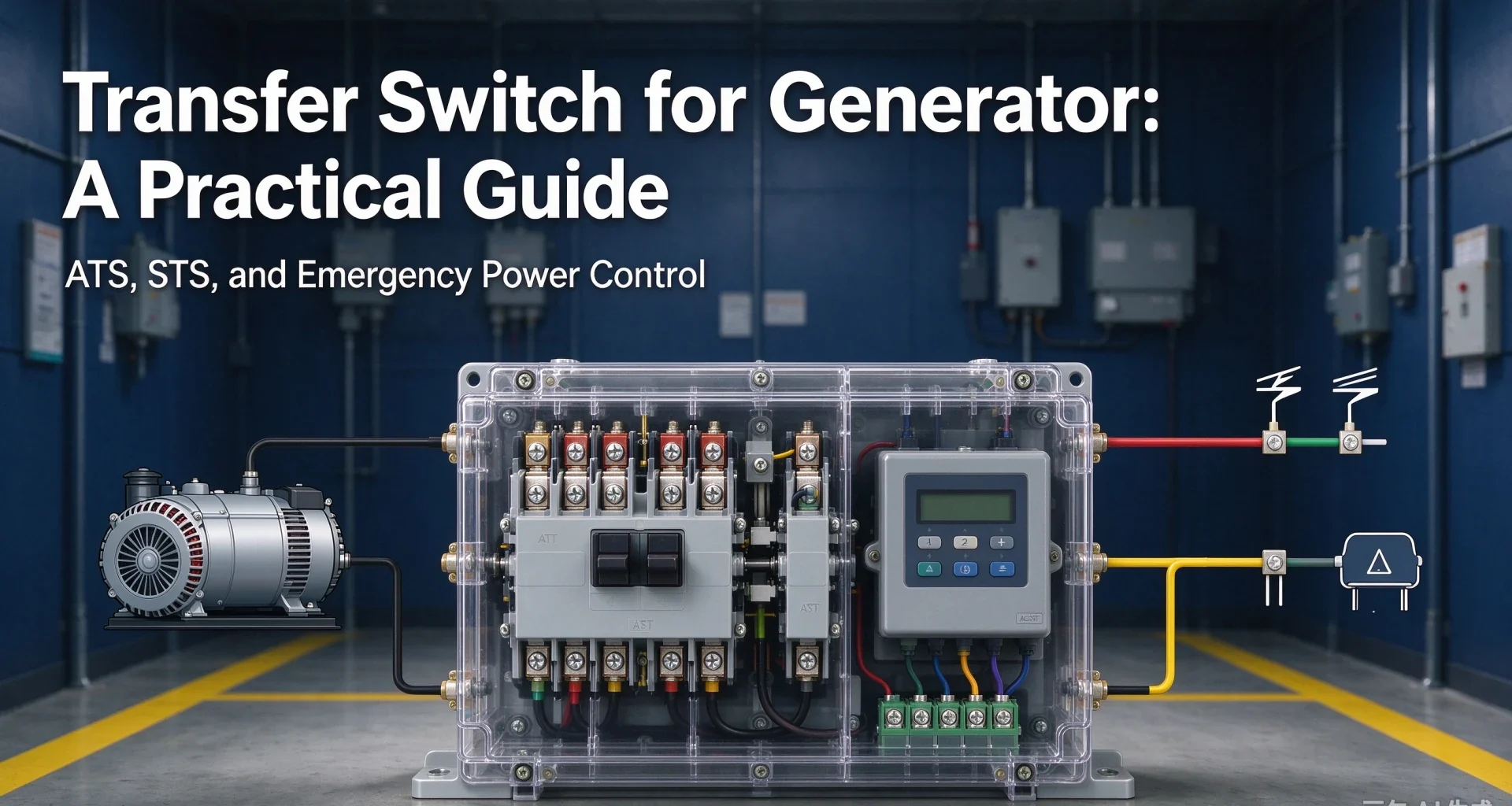
Transfer Switch for Generator: A Practical Guide
A transfer switch for generator moves the load between utility and standby and never lets the two sources touch. Types, sizing, automatic transfer switch configuration, settings and the nuisance transfers that follow.
Transfer switch for generator service is the single device that moves a building’s load from the utility to the standby set and back, and it never lets the two sources touch. Ratings run from 30 A residential panels to 4,000 A industrial services, under UL 1008 in North America and IEC 60947-6-1:2026 nearly everywhere else. Select it badly and the outage outlasts the fuel tank.
Two boundaries keep the page honest. Fault detection on the generator itself belongs to the relays per IEC 60255-1:2022, labelled with the device numbers of ANSI/IEEE C37.2-2022; the transfer switch for generator service is a switching device, not a protection relay, although ANSI 83 marks its control function. And sizing starts from the load calculation of NEC Article 702 (NFPA 70, 2026 edition), not from the generator nameplate alone.
Depth lives elsewhere on this site: the emergency generator panel components page covers the enclosure and its parts, the generator reverse power protection settings page covers the relay that stops the set motoring, and the ANSI device number chart decodes every function number used below. What follows is the switch itself: the sequence, the types, the sizing arithmetic, the costs, and the mistakes that surface at commissioning.
Written by Leon Zhang, Protection Application Engineer · Technical review by Li Ming, Electrical Engineer · Last reviewed October 2026
At a Glance: Numbers That Decide the Choice
- Open transition breaks the utility before the generator closes: 3 to 5 cycles of dead bus, about 60 to 100 ms at 50 Hz.
- UL 1008 requires a withstand and closing rating; typical WCR values span 10 kA to 42 kA at 480 V against the available fault current.
- NEC Article 702 lets optional standby systems feed all or selected loads; Article 700 emergency systems must restore power within 10 seconds.
- A 400 A switch at 400 V three phase carries about 277 kVA; a 100 A residential switch carries about 69 kVA.
- Engine start, warm-up and retransfer delays are adjustable; retransfer delays of 5 to 30 minutes let the utility prove itself first.
- Monthly exercise under load is the NFPA 110:2025 expectation for Level 1 systems; annual stepped load tests catch fuel and cooling faults.
- Closed transition versions parallel with the utility for less than 100 ms, and most utilities require written permission before you buy one.
- Switched neutrals, service entrance ratings and bypass isolation change the price and the inspection outcome more than brand names do.
What a Transfer Switch for Generator Actually Does
The job sounds trivial until the failure modes show up. Two sources, one load, and one iron rule: they must never be connected together unless the interconnection was designed for it.
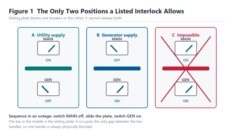
An uncontrolled parallel closes two grids against each other with the generator at the wrong frequency, and the result is bent shafts, tripped breakers and an inspection report nobody wants to write. The transfer switch exists to make that mistake physically impossible, with a mechanical interlock that blocks both contacts from closing at once.
What separates a transfer switch for generator duty from a pair of interlocked breakers is the rating logic. A transfer switch is listed and tested as a complete unit: contact endurance under load, withstand and closing rating against the available fault current, and the neutral and pole configuration as certified combinations. A field-fabricated interlock inherits none of that evidence, which is why inspectors and insurers keep asking for the listing label.
Open transition is the default. The utility contact opens, a dead gap of 60 to 100 ms follows, then the generator contact closes.
Computers ride through on their power supplies, motors coast a few radians, and downstream contactors drop out and restart. That gap is the price of simplicity, and most buildings pay it without noticing.
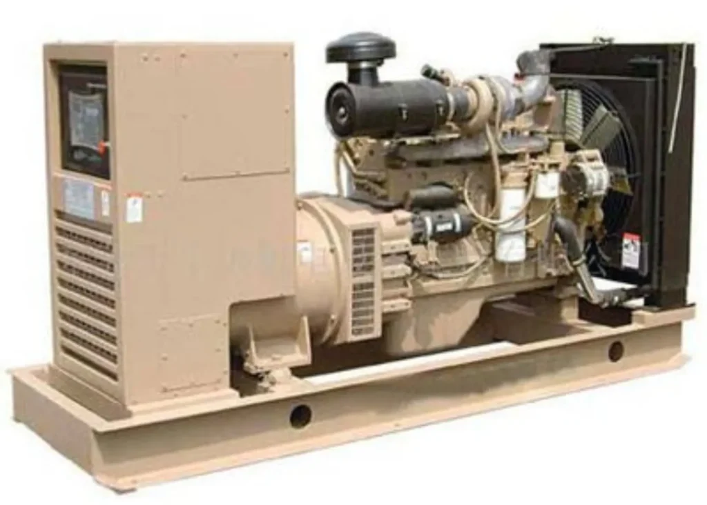
Closed transition buys the gap back. The switch parallels both sources for less than 100 ms while load moves across, which keeps contactors and process lines up. The parallel is brief but real, so the utility has to agree to it, the generator needs a synchronism check (ANSI 25) before closing, and the reverse power element on the set must tolerate the short export. Skip any of those three and the saved milliseconds come back as an outage with paperwork.
Emergency, legally required and optional standby systems set the clock. An Article 700 emergency system must be on the generator within 10 seconds of utility loss, an Article 701 system within 60 seconds, and an optional standby system under Article 702 takes as long as its design allows. The switch hardware is often identical; the classification decides the testing schedule and the paperwork.
How a Generator Transfer Switch Sequences the Changeover
The automatic sequence of a transfer switch for generator service has seven steps, and every one of them is a setting somebody can get wrong. Sensing: the controller watches the utility with undervoltage and overvoltage elements, typically picking up at 70 to 90% of nominal and waiting 1 to 3 seconds so that a recloser shot does not start the engine. Start: a signal cranks the engine, usually with a crank limit of three attempts.
Warm-up runs 5 to 30 seconds depending on the set, longer in cold climates. Transfer: the utility contact opens, the interlock verifies the break, and the generator contact closes under a voltage and frequency permissive.
Retransfer is where patience pays. When the utility returns, the controller waits a retransfer delay of 5 to 30 minutes before switching back, because the most dangerous utility is the one that returns for ninety seconds and leaves again. Cool-down runs the set unloaded for a few minutes to shed heat. The table reflects typical ranges; the project specification wins over any table.
| Parameter | Typical range | Why it exists |
|---|---|---|
| Undervoltage pickup | 70–90% of nominal, 1–3 s delay | Ride through utility recloser shots without starting the engine |
| Overvoltage pickup | 105–110% of nominal | Catch regulator failures before the loads see them |
| Crank limit | 3 attempts of about 10 s | Protect the starter motor from a fuel or mechanical fault |
| Warm-up / off-load run | 5–30 s | Stabilize voltage and frequency before the load lands |
| Retransfer delay | 5–30 min | Wait out unstable utility returns |
| Cool-down | 0–10 min | Shed heat after a loaded run |
Manual transfer skips the brain but keeps the interlock. A manual double-throw switch, or a pair of mechanically interlocked breakers driven by a 43-class selector with auxiliary relays per IEC 61810-1:2015, still guarantees break-before-make, and plenty of small plants run this way for years. The cost is reaction time: somebody has to be there, with a flashlight, when the utility drops.
Types of Transfer Switch: Manual, Automatic and Bypass Isolation
| Type | Switching element | Transfer time | Where it fits |
|---|---|---|---|
| Manual double-throw (MDT) | Two interlocked contact sets | Human speed (minutes) | Small panels, pumps, farms |
| Contactor-type automatic | Mechanically interlocked contactors | 60–150 ms | Residential and light commercial, up to about 1,200 A |
| Breaker-type automatic | Two electrically interlocked breakers | 100–500 ms | Commercial and industrial services, 400–4,000 A |
| Service-entrance rated | ATS with integral service disconnect | As above | Where the switch stands at the service entrance |
| Bypass isolation | ATS plus isolation handles | As above, plus serviceability | Hospitals and plants that cannot de-energize to service the switch |
| Static transfer switch | Thyristors | 4–10 ms | Data halls and process loads with UPS front ends |
| MV automatic bus transfer | Two incomer breakers, scheme logic | 0.3–2 s | Dual-incomer substations, ANSI 83 schemes |
Contactor types dominate below 1,200 A because they are cheap, fast and light, and their coils and mechanisms follow IEC 60947-4-1:2023. The trade is endurance: contactors are built for frequent operation, and their contacts erode with each transfer under load. Breaker types cost more up front, carry higher withstand ratings and give you a maintainable device with accessories, which is why industrial transfer switch specifications almost always land on the breaker frame.
Bypass isolation solves the maintenance paradox: an automatic transfer switch that cannot be de-energized still needs its contacts inspected. The bypass path carries the load while the transfer section is isolated behind visible disconnects.
Hospitals buy them for exactly this reason, and the price shows it.
Static transfer switches are a different species. Thyristors move the load in 4 to 10 ms with no moving parts, which is why data halls pair them with UPS modules. They cost several times an electromechanical switch of the same current and they dissipate heat continuously, so they appear only where milliseconds have a budget.
Above 1 kV the catalogue thins out. Medium-voltage changeover is engineered as an automatic bus transfer scheme with two incomer breakers, synchronism-check permissives and interlocks, coordinated with the plant’s bus protection. Equipment exists as a product family, but the selection is a protection study, not a shopping decision.
Choosing an Automatic Transfer Switch for Generator Service
An automatic transfer switch is the same device as a transfer switch for generator duty, with the operator replaced by a controller. What changes is the volume of configuration: poles, neutral arrangement, control source and start interface all get decided before anyone trusts the controller to act alone. Four of those decisions are made on paper and never revisited.
Poles follow the earthing system, not the catalogue page. A three-pole automatic transfer switch suits a separately derived generator with its own neutral-earth bond, where the neutral stays continuous through the switch. Four-pole units break the neutral as well, which is what a system with a single earthed point needs when the generator is not a separately derived source. Getting this backwards puts earth fault current on the wrong path, and no relay setting fixes it.
| Neutral arrangement | What the switch does | Where it belongs |
|---|---|---|
| Solid neutral | Neutral is a plain busbar, never broken | Separately derived generator with its own neutral-earth bond at the set |
| Switched neutral | Fourth pole opens with the phase poles | Systems where only one neutral-earth bond may exist at a time |
| Overlapping neutral | Neutral makes before and breaks after the phases | Loads that cannot lose a neutral reference, such as sensitive electronics |
Control power is the second decision. Take it from the utility side and the controller goes dark exactly when it is needed; the usual answer is to derive it from whichever source is live, through a small internal changeover, or from a battery. An automatic transfer switch controller that loses its own supply mid-sequence leaves the mechanism parked between sources.
The third is the start interface. Almost every generator controller expects a 2-wire start: a dry contact closes, the set cranks and runs, the contact opens and the set stops after cool-down. Three-wire and remote-start variants exist, and a mismatch here is the most common reason a new automatic transfer switch sits idle while the engine runs perfectly on manual.
The fourth is pickup and dropout. Undervoltage pickup at 70 percent with dropout at 90 percent gives a 20-point band, and too narrow a band makes the automatic transfer switch chatter when a large motor starts nearby. Set the band from the voltage sag your own load produces, measured on site, not from the factory default.
Sizing an Electric Generator Transfer Switch
Current decides the frame, and the arithmetic is fixed: generator current in amperes equals kVA times 1,000 divided by (voltage times 1.732) for three phases. An 800 kVA set at 400 V delivers about 1,155 A, so the frame is 1,200 or 1,600 A, not 800. Sizing an electric generator transfer switch below the generator’s rated current converts it into the weakest link, and the first motor-starting surge finds it.
Load calculation first, generator second, switch third. NEC 702.4 requires the optional standby source to have the capacity for the load calculated under Article 220, and the transfer equipment to be rated for the same current. Motor inrush gets checked separately: the largest motor’s starting current plus the running load must sit inside the switch’s closing and withstand capability. A 100 kW motor block on a soft-start scheme and the same block across-the-line can demand different frames from an identical generator.
Homes simplify to two shapes. A six-circuit sub-panel takes the circuits that matter (well pump, refrigerator, a lighting circuit or two) and suits a 7 to 12 kW portable set. A whole-service switch of 100 to 200 A sits between the meter and the breaker panel and pairs with a 14 to 24 kW standby set; the meter-mounted variants save a wall but turn every wiring change into a utility coordination exercise. Either way the switch belongs after the meter and before the breakers, with the neutral arrangement (solid or switched) decided by the service design, not by habit.
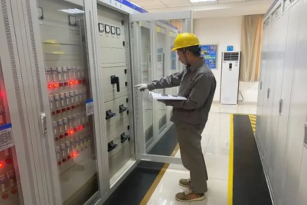
Whole house sizing follows the same arithmetic with a shorter menu. A 200A automatic transfer switch in an SE rated enclosure sits between the meter and the main panel, carries the entire service, and pairs with a 14 to 24 kW air-cooled set. The SE rated version matters because it lets the switch act as the main disconnect, which removes a second enclosure and a set of lugs.
Where the set is smaller than the service, load management fills the gap. The automatic transfer switch sheds the water heater, the second air conditioner and the EV charger while the load is on generator, then restores them in priority order. That is how a 200 A panel runs on a 12 kW set without tripping the generator breaker on the first cold morning. Solar adds one more case: a grid-tied inverter has to be disconnected from the generator as well as from the utility, because most inverters cannot follow a small set’s frequency, so the scheme needs a second contactor or an inverter with a generator input.
Enclosure and environment move the frame price as much as amps do. NEMA 1 indoors, NEMA 3R outdoors, 4X stainless near salt water; enclosure heaters below -25°C; seismic bracing where the structural report asks for it. The table shows typical pairings between frame, generator and application.
| Switch rating (400 V, 3-phase) | Generator it can carry | Typical application |
|---|---|---|
| 100 A | About 69 kVA | Homes, small shops, 7–24 kW standby sets |
| 250 A | About 173 kVA | Farms, fuel stations, small workshops |
| 400 A | About 277 kVA | Light industry, clinic and hotel services |
| 800 A | About 554 kVA | Industrial services, water pumping stations |
| 1,600 A | About 1,108 kVA | Process plants, data halls on a single bus |
| 3,000 A | About 2,078 kVA | Campus services, engineered LV distribution |
Where the Transfer Switch Sits in the Standby Power Chain
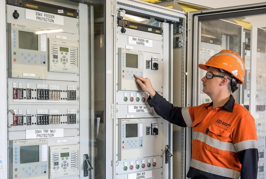
The standby chain has four heads: the generator controller, the transfer controller, the protection relays and the loads. The generator controller owns starting, fuel, voltage and the set’s own protection, including the ANSI 32 reverse power element that trips when the set starts motoring instead of generating; the settings live on the generator reverse power protection page, and the wider principle is on the reverse power flow protection page.
The transfer controller owns the changeover only. It senses voltage on both sources, runs the sequence, and reports.
Modern versions are ATS controller modules that speak Modbus or IEC 60870 upward, so plant SCADA sees utility-fail and switch-position events without a second panel; one example is the ATS controller module in the low-voltage range. The emergency generator panel page shows how the controller, battery charger and metering gather into one line-up.
Paralleling is a different topology and a different product. When several sets run together against the utility, load sharing and synchronizing take over, and the right equipment is a panel built around an ANSI 25 synchronism check, as described in the generator synchronization panel selection guide. Buying a transfer switch for a paralleling project is the classic specification error, and it is cheaper to fix on paper.
One boundary stays absolute. Unless closed transition was engineered, permitted and set, the answer to whether the sources may run together is no.
Cost, Lead Time and What Moves the Price
Catalogue prices move with amps, poles and certification. Indicative hardware ranges, excluding installation: a 100 to 200 A contactor-type unit lands between roughly $600 and $2,500, and breaker-type frames from 400 to 800 A run $3,000 to $9,000.
Bypass isolation starts near $15,000 and climbs with the service rating. Static transfer switches price several times their electromechanical equivalent. A transfer switch for generator service at medium voltage is project-priced together with the switchgear line-up.
Installation often equals the hardware. Service-entrance units mean a utility coordination visit, a permit, and an inspector who wants to see the listing label and the wiring diagram.
Switched neutrals, outdoor enclosures and long generator cable runs each add a line item. Budget the electrician’s hours before choosing between two brands that differ by $200.
Lead time is the quiet differentiator. Catalogue residential units ship in days; commercial breaker-based frames in 2 to 6 weeks; engineered service-entrance or bypass units in 8 to 16 weeks, longer when seismic or marine certification enters. Projects that discover the ATS late pay expedite fees or run their commissioning date on a rented set.
Testing and Maintenance under NFPA 110:2025
NFPA 110:2025 asks Level 1 systems for a monthly exercise, and the meaningful version of that test is an actual transfer: open the utility source with a test switch, let the sequence run, transfer back. Monthly no-load engine runs keep the set warm but prove nothing about the switch contacts, the interlock or the retransfer delay.
Annual maintenance opens what monthly tests cannot see. Contact resistance measured in the hundreds of microohms or lower, mechanism lubrication, torque checks on power terminations, control battery voltage under load.
One more check matters: the withstand rating still has to exceed the present available fault current, because networks grow and fault duties rise. The same staged discipline applies on the generator protection side, where the differential protection test procedures document every trip path.
Record keeping is part of the standard. NFPA 110 expects the transfer equipment to appear in the maintenance schedule with documented results, and insurers increasingly ask for the log at renewal. A switch that transfers cleanly every month for ten years and has no paperwork is, from the auditor’s chair, a switch that has never been tested.
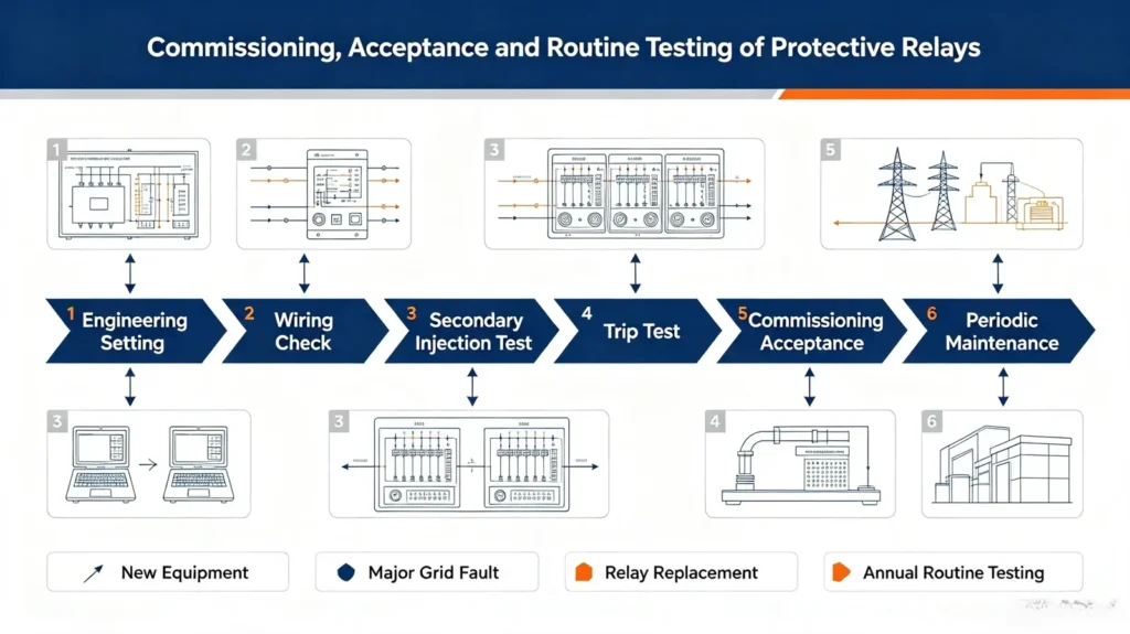
Why an Automatic Transfer Switch Transfers When It Should Not
Nuisance transfers are the most common complaint on a new installation, and they are almost always a setting rather than a failed component. Five causes cover the field.
- Undervoltage pickup set too close to nominal. A pickup at 92 percent makes the automatic transfer switch trip on the sag from a 100 kW motor start two bays away. Move the pickup to 70 to 80 percent and the same sag rides through.
- Confirm delay too short. One second catches a genuine outage and also catches a recloser shot. Two to three seconds costs nothing and removes most nuisance starts.
- Hunting between sources. If the retransfer threshold sits below the dropout threshold, the automatic transfer switch transfers back, sees the utility dip, and transfers out again. Keep at least a 10-point gap between the two settings.
- Control supply taken from the load side. The switch transfers, the control transformer goes dead with the utility, and the mechanism stops half way. Feed the controller from the live side or from a battery.
- Generator permissive set too loose. Closing onto a set at 80 percent voltage and 45 Hz drags the bus down, the undervoltage element sees it, and the switch trips straight back. Require 90 percent voltage and 95 percent frequency before the close command.
An open neutral belongs on the same list and behaves differently. When the neutral pole opens before the phase poles, or a lug was never torqued, the load sees line-to-line voltage through the connected equipment and half the electronics in the building fail at once. That is why overlapping neutral arrangements exist, and why the neutral torque check belongs in annual maintenance rather than in the commissioning checklist alone.
When a Transfer Switch for Generator Is the Wrong Answer
A transfer switch for generator backup solves one problem: one load group, one standby source, one changeover. Five situations call for something else:
- Continuous prime power. Where the set runs as the everyday source and the utility is the backup or absent, the transfer switch has nothing to do; the generator controller and the fuel logistics run the plant.
- Paralleled generator fleets. Several sets on one bus need synchronizing and load sharing; the correct equipment is a synchronization panel, and bolting an ATS onto that bus just adds a single point of failure.
- Medium-voltage bus sections. Dual-incomer substations transfer through engineered ANSI 83 schemes with synchronism-check permissives and bus protection coordination, sized by a short-circuit study rather than by catalogue amps.
- Loads that cannot tolerate 60 ms. Data and process loads riding on UPS modules want a static transfer switch, or nothing at all where the UPS outputs are already paralleled internally.
- One small load. A single freezer or pump does not justify a service-sized frame; an interlock kit on the existing breaker panel with a generator inlet is the economical, code-recognized path for portable sets.
The pattern behind all five: match the switching topology to the sources, not to the budget line.
The cheapest failure to avoid is the one designed out on paper.
Frequently Asked Questions
What does a transfer switch do?
The device connects a load to exactly one source at a time. During an outage it breaks the utility connection, confirms the break and closes the generator side, then reverses the process when the utility returns, so the two sources can never feed the same wires uncontrolled.
How does a generator transfer switch work?
A controller senses utility voltage, starts the engine, waits through warm-up, opens the utility contact through a mechanical interlock and closes the generator contact under a voltage and frequency permissive. Retransfer waits 5 to 30 minutes after the utility returns, then the set runs a cool-down.
What size transfer switch do I need for a generator?
The transfer switch for generator use must carry at least the generator’s rated current: kVA times 1,000 divided by voltage times 1.732 for three phases. An 800 kVA set at 400 V delivers about 1,155 A, so a 1,200 A or 1,600 A frame fits; a 24 kW home standby set at 240 V draws about 100 A.
Can I connect a generator without a transfer switch?
Not to building wiring. Backfeeding a panel through a cord or an unlisted connection energizes utility lines and has killed line workers, and NEC Article 702 requires listed transfer equipment or a listed interlock. A transfer switch, or an interlock kit with a generator inlet, is the compliant route.
How much does a transfer switch cost?
Indicative hardware: $600 to $2,500 for 100 to 200 A contactor types, $3,000 to $9,000 for 400 to 800 A breaker types, from about $15,000 for bypass isolation. Installation, permits and utility coordination commonly add half to all of the hardware cost.
What is the difference between an ATS and a synchronization panel?
An ATS moves one load between two sources that never run together. A synchronization panel parallels several generators, or generators with the utility, on one bus with load sharing and an ANSI 25 synchronism check. The two topologies answer different questions and are not interchangeable.
How often should a transfer switch be tested?
NFPA 110:2025 expects Level 1 standby systems to exercise monthly, and the meaningful test is a real transfer under load, not just an engine run. Annual maintenance adds contact resistance, mechanism and control checks, with the results documented.
Conclusion
A transfer switch for generator duty is chosen from arithmetic, not from habit: load calculation first, generator current second, fault withstand third, and the brand somewhere after that. The sequence is a short list of settings somebody has to own, the types differ in speed and serviceability more than in intelligence, and the testing rhythm is monthly, under load, on paper. Specify it that way and the changeover becomes the least interesting event of the outage, which is exactly the point.
Related Reading
- Emergency generator panel: components, functions and protection, the enclosure that often houses the transfer controller.
- Generator reverse power protection (ANSI 32): settings and testing, the element that must tolerate a closed-transition export.
- ANSI protection relay codes: device number chart, the labels behind 25, 27, 32, 43 and 83 used throughout this page.
- How to select a generator synchronization panel, the topology for paralleled fleets that a transfer switch cannot cover.
- Generator protection relay product range, the relay families referenced across the standby chain.
Technical References
| Standard | Covers | Edition used |
|---|---|---|
| UL 1008 | Transfer switch equipment: listing, withstand and closing rating, endurance | Ed. 9 (2015, revised 2018) |
| IEC 60947-6-1 | Multiple function equipment: transfer switching devices, utilization categories | 2026 |
| IEC 60947-4-1 | Contactors and motor starters used inside ATS assemblies | 2023 |
| IEC 61810-1 | Electromechanical relays for transfer logic and interlock circuits | 2015 |
| IEC 60255-1 | Common requirements for measuring relays and protection equipment | 2022 |
| ANSI/IEEE C37.2 | Device function numbers: 25, 27, 32, 43, 59, 81, 83 | 2022 |
| NFPA 110 | Emergency and standby power systems: classification, testing intervals | 2025 |
| NFPA 70 (NEC) | Articles 700, 701 and 702: emergency, legally required and optional standby systems | 2026 |
Written by Leon Zhang, Protection Application Engineer · Technical review by Li Ming, Electrical Engineer · Last reviewed 2026-10-19
About Author

Hello, I'm Leno Zhang. I have 15 years of experience in the power relay protection industry with extensive pre-sales and after-sales project experience. Our company specializes in various complete sets of relay protection and automation equipment. I can assist customers in solving all practical on-site project challenges and provide optimal integrated solutions.
Tell Us Your Requirement
High Quality
Stable performance, reliable design, ensuring safe operation for power system protection and grid stability.
Fast Delivery
Timely delivery to support your urgent orders and project schedules efficiently and professionally at any time.
Best Warranty
Professional Warranty: Reliable after-sales support for stable relay protection and long-term customer satisfaction.