

-
Leon Zhang sales consultant
-
Email: zxl635973785@gmail.com
-
Phone/WhatsApp: +86 13655813266
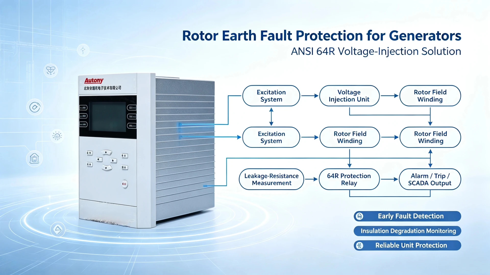
How to Choose a Rotor Earth Fault Relay for a Generator
Rotor earth fault protection for generators (ANSI 64R) serves as the core safety device for DC excitation systems of various synchronous generators. Normally, the rotor field circuit operates in an isolated ungrounded condition, so minor insulation defects cannot be detected by conventional monitoring.
Single‑point or double earth faults caused by moisture, dust, vibration and insulation aging will result in unbalanced magnetic fields, rotor overheating, severe unit vibration and unplanned outages, leading to heavy economic losses.
For industrial power projects, engineers shall select either voltage‑injection or ping‑pong rotor earth fault protection for generators according to generator capacity, excitation design and site operating conditions, to ensure stable unit performance and reliable predictive maintenance.
What Is Rotor Earth Fault Protection of a Generator?
Synchronous generator rotor windings operate on isolated DC excitation circuits. The rotor field circuit has no intentional earth connection under normal operating conditions. Insulation degradation from moisture, dust, carbon‑brush debris or mechanical fatigue can create leakage paths to ground.
Two critical fault conditions occur in rotor circuits:
- First rotor earth fault: Only one ground contact exists. No closed short‑circuit loop forms. Generator can keep running; protection should trigger alarm only, not immediate trip. Operators should arrange maintenance during the next available shutdown window.
- Second rotor earth fault: Two separate ground points create a short‑circuited section of the rotor winding. Magnetic field becomes unbalanced, producing heavy local heating, excessive vibration and permanent mechanical damage to rotor forging or winding bars, leading to forced plant outages.
64R protection (ANSI device number 64R, also known as generator field ground‑fault protection) continuously monitors rotor‑to‑ground insulation resistance to catch these insulation defects early.
Why Is Rotor earth fault protection for generators (ANSI 64R) Critical for Generator Safety?
Rotor insulation failure develops gradually. Common root causes include insulation aging, humid environment contamination, carbon‑brush dust accumulation, continuous mechanical vibration and exciter‑side anomalies.
Consequence summary table:
| Fault Condition | Protection Action | Plant Consequence |
|---|---|---|
| Single rotor earth fault | Alarm | No immediate hardware damage; elevated risk of subsequent second fault |
| Double rotor earth fault | Trip (mandatory) | Rotor winding short‑circuit, uneven excitation, rotor overheating, mechanical vibration, catastrophic generator damage, unplanned outage |
For EPC and asset‑owner teams, properly sized 64R protection lowers capital loss from unexpected generator repairs and avoids revenue loss from unscheduled shutdown events. Even small‑to‑medium‑size diesel or gas‑turbine generators should include basic rotor earth‑fault monitoring.
Common Rotor Earth Fault Detection Methods
Two mainstream field‑proven technologies are widely deployed for 64R rotor earth‑fault relays: voltage‑injection method and ping‑pong (bridge‑balance resistance‑switching) method. Implementation differs for brush‑type versus brushless‑excited generators.
Voltage Injection Method
Low‑frequency AC or square‑wave test signal is continuously injected into the isolated rotor DC circuit. The relay measures leakage resistance by analysing return signal amplitude.
- Advantages: Continuous online monitoring, high measurement sensitivity, stable readings with rotor rotating under full load, suitable for large critical generators.
- Applications: Hydro‑generators, large steam‑turbine units, gas‑turbine generators.
- Notes: Brushless‑excited generators need specially adapted injection coupling hardware to pass monitoring signals across rotating exciter assemblies.
Ping‑Pong Method (Alternate Resistance Switching / Potentiometer Bridge)
Relay switches reference balance resistors alternately and compares rotor circuit voltage balance to calculate insulation resistance.
- Advantages: Simple hardware structure, lower total project cost.
- Limitations: Lower sensitivity; measurement accuracy degrades with fluctuating excitation voltage and dynamic operating conditions; not ideal for large high‑value generator assets.
Method Recommendation by Excitation Architecture
| Generator Excitation Type | Recommended Detection Approach |
|---|---|
| Brush‑excited generator | Voltage injection (preferred); ping‑pong for cost‑sensitive small units |
| Brushless‑excited generator | Specialised voltage‑injection system; ping‑pong generally not recommended |
| Hydroelectric generator | High‑sensitivity continuous voltage‑injection 64R relay |
| Steam‑turbine generator | Online voltage‑injection monitoring |
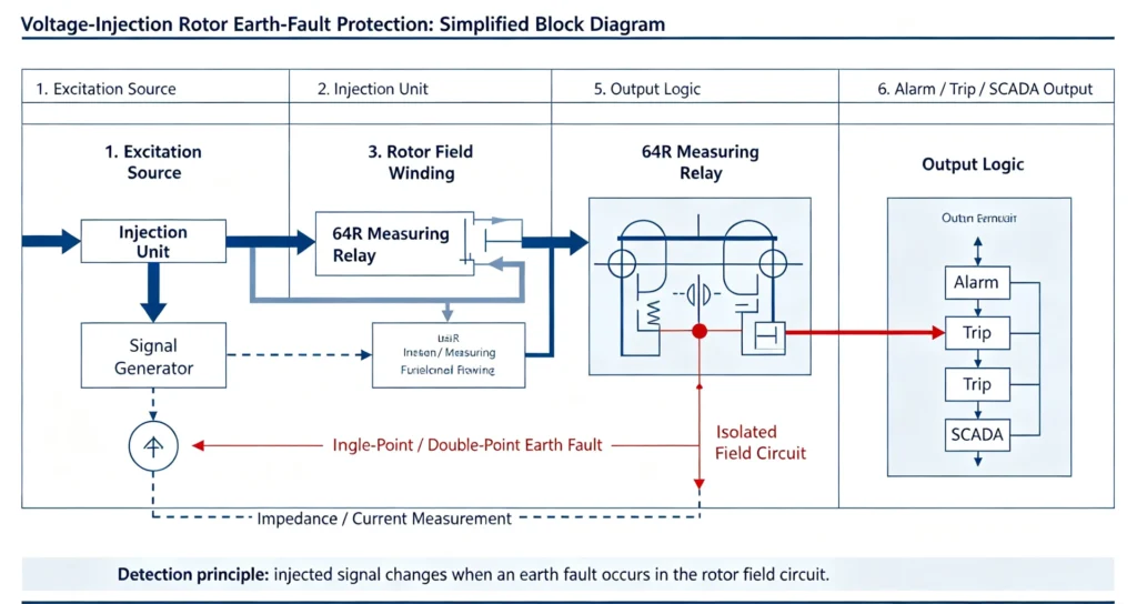
Key Technical Parameters for Selecting a 64R Rotor Earth Fault Relay
This section delivers actionable specification criteria for EPC tender evaluation and equipment datasheet review.
Generator Rated Capacity Reference
| Generator Capacity | Protection Requirement |
|---|---|
| < 5 MW | Basic 64R protection, alarm priority |
| 5 MW‑50 MW | Continuous online insulation monitoring |
| > 50 MW | High‑accuracy voltage‑injection 64R relay, full alarm‑trip logic |
Excitation DC Voltage Matching
Check generator excitation system rated DC voltage before relay selection. Common excitation levels: 110 VDC, 220 VDC, 300 VDC, 500 VDC. The selected 64R relay must tolerate full rotor excitation DC voltage; mismatch will cause measurement failure or hardware burnout.
Ground‑Resistance Measurement Range
Typical available measuring ranges:
- 1 kΩ – 500 kΩ (general‑purpose)
- 1 kΩ – 1 MΩ (high‑sensitivity for early insulation degradation trending)
Wider upper resistance threshold enables detection of slow insulation deterioration long before a hard fault develops.
Alarm & Trip Resistance Thresholds (Typical Engineering Settings)
These values serve as reference only; final settings shall follow project‑specific protection coordination study and manufacturer manuals.
| Function | Typical Resistance Setting | Purpose |
|---|---|---|
| Alarm stage | 20 kΩ – 50 kΩ | Early warning of dropping insulation resistance |
| Trip stage | 5 kΩ – 10 kΩ | Trip generator when severe rotor‑to‑ground leakage occurs |
Time‑delay settings (3 – 10 seconds for alarm; 1 – 3 seconds for trip) avoid nuisance operation caused by transient noise.
Communication & System Integration
EPC and plant‑owner projects require interoperability with existing SCADA and automation platforms. Verify supported interfaces:
- Modbus RTU
- IEC 61850 MMS
- Ethernet TCP/IP
Relays without digital communication only provide local hard‑contact outputs, which increase site‑wiring workload for modern digital power plants.
Step‑by‑Step Selection Workflow
Follow these six steps for consistent, traceable relay selection during tender and detailed‑engineering phases:
- Define generator prime‑mover type: hydro, steam turbine, gas turbine or diesel generator.
- Identify excitation system architecture: static brush‑excited or brushless excitation.
- Select monitoring principle: voltage injection or ping‑pong method based on unit criticality and budget constraints.
- Determine alarm and trip resistance thresholds: align with generator OEM recommendations and site protection philosophy.
- Confirm communication requirements: check SCADA / DCS interface requirements for the plant.
- Verify standard compliance: confirm relay meets relevant industry standards including IEC 60255, IEC 60034, IEEE C37.2 and IEEE C37.102 generator‑protection guides.
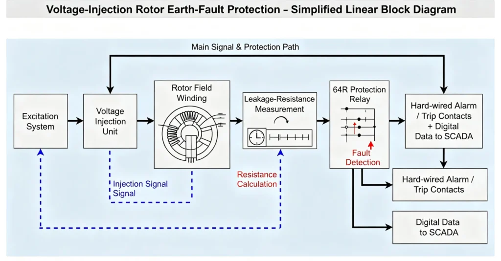
Typical Rotor Earth‑Fault Protection Scheme
Simplified functional sequence for voltage‑injection 64R system:
Excitation System → Voltage Injection Unit → Rotor Field Winding → Leakage‑Resistance Measurement → 64R Protection Relay → Hard‑wired Alarm / Trip Contacts + Digital Data to SCADA
Practical Selection Examples by Plant Type
Hydroelectric Generator
- Unit characteristics: Large rotor dimensions, high ambient humidity, long rotor‑excitation cabling, risk of gradual moisture‑driven insulation drop.
- Recommendation: High‑sensitivity voltage‑injection‑based 64R rotor earth‑fault relay with wide resistance measuring range.
Steam‑Turbine Generator
- Unit characteristics: High‑speed continuous base‑load operation; carbon‑brush contamination is a known degradation source.
- Recommendation: Continuous online monitoring voltage‑injection relay, digital communication for SCADA trending.
Diesel Generator
- Unit characteristics: Small‑to‑medium capacity, standby or distributed‑generation duty cycle, cost‑sensitive project budget.
- Recommendation: Economical 64R relay solution; ping‑pong is acceptable for non‑critical small units; voltage injection preferred for important backup generators.
Frequent Selection Mistakes to Avoid
- Ignoring excitation DC voltage rating: Relay cannot withstand rotor excitation voltage leads to measurement failure or hardware damage.
- Insufficient insulation‑resistance measuring range: Miss early insulation‑degradation trends.
- Relying purely on offline periodic testing: Offline megger tests cannot catch faults occurring during generator running; online 64R monitoring is mandatory for critical assets.
- Overlooking digital‑communication requirements: Local‑only contact‑output relays create extra integration effort for modern automated power stations.
- Applying standard brush‑excited relay for brushless‑excited generators: Conventional injection hardware cannot couple test signals into rotating brushless‑exciter circuits, protection will not function correctly.
Frequently Asked Questions
Q: What ANSI device number corresponds to rotor earth‑fault protection?
A: ANSI 64R (Rotor / Field Winding Earth Fault Protection).
Q: Does first rotor earth fault trigger generator trip?
A: Standard practice is alarm‑only for single ground fault. Trip is applied for second ground‑fault condition or extremely low insulation resistance threshold.
Q: Voltage injection versus ping‑pong: which solution is better?
A: Voltage injection delivers higher sensitivity and continuous full‑load monitoring; it is preferred for medium‑and‑large critical generators. Ping‑pong offers lower cost for small, non‑critical generators, with reduced accuracy under variable operating conditions.
Q: Can brushless‑excited generators implement 64R rotor earth‑fault protection?
A: Yes. But standard brush‑excited relay hardware will not work; dedicated adapted injection coupling assemblies are required for brushless‑excited machine installations.
Technical References & Source Documents
- IEEE C37.2‑2008, IEEE Standard Electrical Power System Device Function Numbers, American National Standards Institute (ANSI)
- IEEE C37.102‑2006, IEEE Guide for AC Generator Protection
- IEC 60255‑1: Measuring Relays and Protection Equipment, General Requirements
- IEC 60034‑1, Rotating Electrical Machines – Rating and Performance
- ABB Generator Protection Fundamentals Application Guide (public technical white‑paper)
- Protection relay manufacturer application manuals for rotor earth‑fault 64R function, including low‑frequency injection implementation notes



About Author

Hello, I'm Leno Zhang. I have 15 years of experience in the power relay protection industry with extensive pre-sales and after-sales project experience. Our company specializes in various complete sets of relay protection and automation equipment. I can assist customers in solving all practical on-site project challenges and provide optimal integrated solutions.
Tell Us Your Requirement
High Quality
Stable performance, reliable design, ensuring safe operation for power system protection and grid stability.
Fast Delivery
Timely delivery to support your urgent orders and project schedules efficiently and professionally at any time.
Best Warranty
Professional Warranty: Reliable after-sales support for stable relay protection and long-term customer satisfaction.