
-
Leon Zhang Sales Manager
-
Email: sale@relayprotect.com
-
Phone/WhatsApp: +86 13655813266
Intelligent Electronic Device: Functions and IEC 61850
What an intelligent electronic device is, the four functions inside it, how it sits on IEC 61850, and the eight lines to settle before you specify one.
What is an intelligent electronic device?
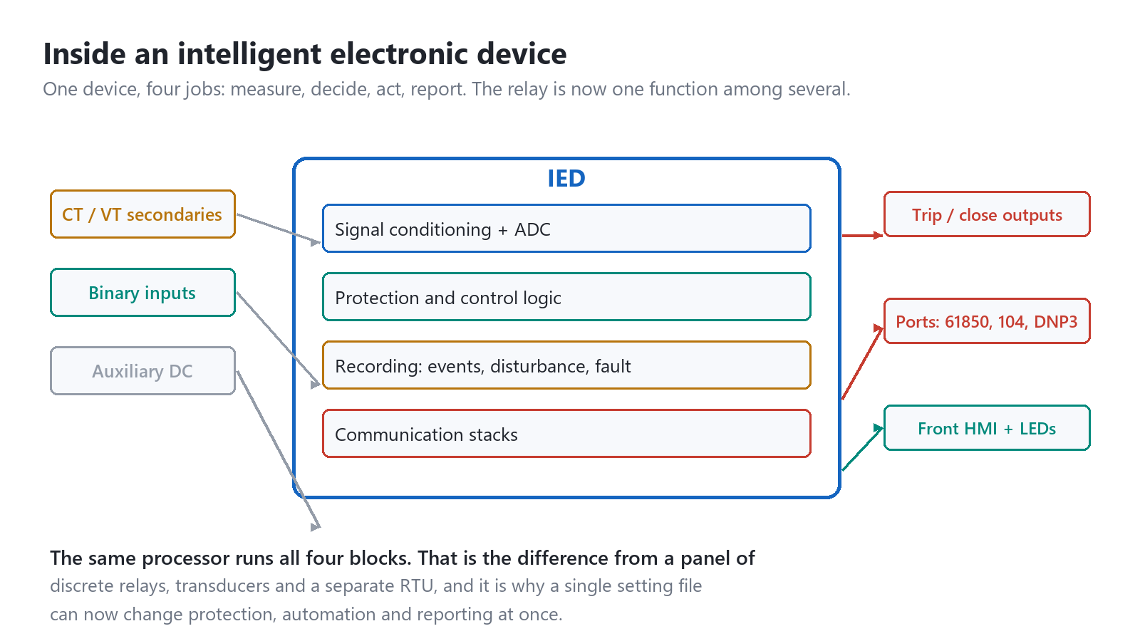
An intelligent electronic device is the industry term for a microprocessor-based unit that measures CT and VT secondaries, runs protection and control logic, drives trip outputs and reports over a network, all in one enclosure. IEC 60255-1:2022 sets the common requirements, and IEEE C37.2-2022 fixes the function numbers printed on its front. Three things separate it from a digital meter: it samples fast enough for protection, it decides inside a defined cycle time, and it holds a settings file describing every function it runs. Protection needs roughly 4 kHz to resolve a fault current with DC offset – 80 samples per cycle at 50 Hz – while power quality work needs 12.8 kHz or more. A feeder function must pick up, time and trip within one to two cycles, which rules out unbounded scheduling latency. CT and VT secondaries pass through a burden resistor and anti-alias filter into a 16-bit or 24-bit converter. Setting review and quotation within 12 hours, MOQ 1, 7-15 working days.
Intelligent electronic device is the industry term for a microprocessor-based unit that measures CT and VT secondaries, runs protection and control logic, drives trip outputs and reports over a network, all in one enclosure. IEC 60255-1:2022 sets the common requirements it has to meet, and IEEE C37.2-2022 fixes the function numbers printed on its front.
At a glance
- An intelligent electronic device combines measurement, protection logic, trip outputs and communications in one box.
- The trip path does not go through the network stack. Hardwired copper still opens the breaker.
- Consolidation is the trade: eight functions in one box means one failure can remove all eight.
- IEC 61850 gives the device a self-describing data model. MMS carries SCADA traffic, GOOSE carries peer signals, sampled values carry the currents.
- Time sync accuracy decides whether sampled values line up. One microsecond is the working limit.
- Redundancy has to be bought as hardware. It cannot be added by a firmware update later.
- Most field failures are output contacts, power supplies and clocks, not protection algorithms.
What an Intelligent Electronic Device Is
Three things separate this class of device from a digital meter or a programmable relay. It samples current and voltage fast enough for protection, it decides inside a defined cycle time, and it holds a settings file that describes every function it runs.
The sampling rate is the first dividing line. Protection needs roughly 4 kHz to resolve a fault current with a DC offset and a decaying fundamental, which is 80 samples per cycle at 50 Hz. Power quality work needs 12.8 kHz or more. A controller built on a 100 Hz scan cannot see either.
Cycle time is the second. A feeder protection function has to pick up, time and issue a trip within one to two power cycles. That budget rules out an operating system with unbounded scheduling latency, which is why these devices run a real-time kernel or bare metal rather than a general-purpose PLC runtime.
The settings file is the third, and it is the one that causes the most trouble in service. A relay’s behaviour is now defined by data, not by wiring. Nobody can look at the panel and tell what the device will do.
A settings file is a documentation problem before it is an electrical one.
Selecting a relay for a live project?
Send the system voltage, CT ratio and tripping scheme. Our engineers confirm the model and reply within 12 hours.
Four Functions Inside the Box
Every device in this class does the same four jobs in the same order, and the order matters more than the marketing sheet suggests.
Measure. CT and VT secondaries pass through a burden resistor and an anti-alias filter into a 16-bit or 24-bit converter. The filter is not optional: without it, a 2 kHz switching harmonic folds down into the 50 Hz band and appears as a load current that is not there. Numeric relays typically oversample at 4 to 20 kHz and decimate in firmware.
The anti-alias filter is where cheap designs fail first.
Decide. The processed phasors feed the protection elements, each identified by an ANSI device number: 50/51 for instantaneous and time overcurrent, 27/59 for under and overvoltage, 87T for transformer differential, 21 for distance, 79 for reclosing, 86 for lockout. A modern feeder device carries twenty or more of these simultaneously, all reading the same samples.
Act. A decision becomes a contact closure into the trip coil, and this is the part that has to survive twenty years of standing idle. The output relay is a real electromechanical contact in most designs, not a solid-state switch, because a failed-short semiconductor cannot be detected by the self-test that watches it.
Report. The device writes an event log with 1 ms resolution, a disturbance record in COMTRADE format at the sampling rate, and a stream of measurements to whoever is listening. Fault records are usually 3 to 10 seconds long and hold the pre-fault window that makes the record useful.
A good disturbance record answers the question that matters after a trip: what did the device see, what did it decide, and when. Without a stable clock the three answers cannot be lined up across devices.
Intelligent Electronic Device Versus Electromechanical Relay
The comparison is not about accuracy. An induction disc relay and a numeric device both measure current, and the numeric one wins on repeatability. The real difference is how failure behaves.
Eight electromechanical relays on a panel fail one at a time. Each failure removes one function and leaves the other seven working, and the panel keeps protecting the circuit while somebody orders a replacement. One device running eight functions fails as a unit.
Concentration of function cuts both ways.
Self-supervision is what partly pays for that concentration of risk. A modern device watches its own supply rails, firmware checksum, CT circuit continuity and output relay coil, and raises an alarm before the function is needed. Coverage is good but not complete, and the gaps are predictable.
| Aspect | Electromechanical relay | Intelligent electronic device |
|---|---|---|
| Functions per enclosure | One | Twenty or more |
| Setting method | Taps, dial and spring tension | Settings file, often versioned in software |
| Self-supervision | None | Supply, checksum, CT continuity, output coil |
| Failure mode | Silent, no alarm | Usually alarmed, occasionally silent |
| Blast radius of one failure | One function | Every function in the box |
| Event record | None | 1 ms sequence of events plus COMTRADE |
| Test method | Secondary injection, one element at a time | Full scheme injection, plus logic and GOOSE checks |
| Typical service life | 30 to 40 years | 15 to 20 years, limited by electrolytic capacitors |
Table 1. The last row is the one that decides replacement budgets. A 1990s panel of electromechanical relays often outlives the numeric device installed to replace it.
That service life figure deserves a note. The protection algorithm does not wear out. The power supply capacitors dry out, the real-time clock battery dies, and the flash memory holding the settings reaches its write limit. A device that has been in service for eighteen years is a device whose failure rate is no longer the one on the datasheet.
Where the Device Sits in IEC 61850
A substation automation system built to IEC 61850 has three levels and two buses, and the device we are discussing is the only one that has to speak both.
At station level, a gateway or a SCADA front end collects measurements and events over MMS, the client-server part of the standard defined in IEC 61850-8-1:2011. At bay level, protection and control devices exchange peer-to-peer signals over GOOSE, which is a publisher-subscriber message with no server in the middle. At process level, merging units publish digitised currents and voltages as sampled values per IEC 61850-9-2:2011.
GOOSE earns its place through repetition rather than speed. A message repeats at 2 ms, then 4, 8, 16 and so on up to a steady 1 s heartbeat, so a lost frame is recovered in milliseconds without any acknowledgement. That is fast enough for interlocking and, in some designs, for the trip itself.
Repetition, not raw speed, is what makes GOOSE dependable.
Most utilities still hardwire the trip. The reasons are practical: a hardwired circuit can be proved with a multimeter during commissioning, it does not depend on a subscription being correct, and it survives a failed Ethernet port. Sampled values and GOOSE reduce copper, but the trip circuit is the last place most engineers are willing to remove it.

Edition 2 of the standard, consolidated around 2020 with the amendments to parts 8-1 and 9-2, added the pieces that make multi-vendor substitution realistic: a formal data model description in SCL, mandatory functional constraints on each data object, and a defined file transfer service for disturbance records. Edition 3 is in development and has been for years. Designing to Edition 2 today is not a compromise.
Protocols a Substation Actually Uses
Four protocols cover almost every enquiry that crosses a desk, and the choice is usually made by the customer’s existing system rather than by preference.
| Protocol | Transport | Where it fits | What it does not give you |
|---|---|---|---|
| IEC 61850 MMS | TCP/IP, port 102, ISO stack | Substation to gateway, self-describing objects | Nothing, at a price: heavier engineering and a configuration file per device |
| IEC 61850 GOOSE | Layer 2, no IP | Interlocking, breaker failure, trip in digital schemes | Routing across subnets without a transparent bridge |
| IEC 60870-5-104 | TCP/IP, port 2404 | Control centre telecontrol across a wide area | Peer-to-peer signals; it is strictly master to outstation |
| DNP3 | TCP/IP, port 20000 | North American utilities, water and oil networks | An object model for protection functions |
| Modbus TCP | TCP/IP, port 502 | Plant integration, quick retrofits, PLC links | Timestamps, event buffer, any notion of time quality |
Table 2. Five options, but the last row is where most integration projects end up, and where most of the resulting argument starts.
Modbus deserves the warning. It polls a register table, so an event that lasts 300 ms between polls is simply lost. A protection device that trips and recloses inside one poll interval will look, on the SCADA screen, as though nothing happened. If events matter, use a protocol that buffers them and stamps them.
Ask for the full protocol list in writing, before the quotation.
One device often needs three of these at once: MMS to the station gateway, 104 to the control centre, and Modbus to the plant PLC that the client forgot to mention until commissioning. Ask for the full list before the quotation, not after.
Time Synchronisation: The Requirement Nobody Writes Down
Every record the device produces carries a timestamp, and the value of that timestamp depends entirely on a clock the specification usually omits.
The arithmetic is unforgiving. At 4 kHz sampling, consecutive samples are 250 µs apart. A clock error of 1 ms shifts one device’s samples by four positions relative to its neighbour, which is enough to make a line differential scheme see a fault that is not there. That is why the working limit for sampled values and synchrophasors is 1 µs, not 1 ms.
SNTP over the station LAN lands somewhere between 1 and 10 ms on a good day, and much worse when the network is busy. It is fine for SCADA timestamps and useless for sampled values. IRIG-B delivers about 1 µs over dedicated coax, and needs its own cable to every cubicle.
PTP, defined in IEEE 1588-2019 with a power-system profile in IEC 61850-9-3:2016, reaches sub-microsecond accuracy when the Ethernet controller timestamps the frame in hardware rather than in software. Without hardware timestamping the same protocol degrades to something close to SNTP, which is a distinction datasheets tend to blur.
A record from a device with a drifted clock still looks perfect. The waveform is clean, the trigger sits in the right place, and every event carries a timestamp. Compare it with a fault record from the opposite end of the feeder and the two will not line up by anything between 4 and 400 ms. Fault analysis then becomes an argument about clocks instead of an argument about the fault.

Ask two questions of any supplier. Does the device timestamp PTP in hardware, and what does it do when the grandmaster disappears? A clock that free-runs on its own oscillator drifts by roughly 1 to 10 ppm, which is 3 to 30 ms per hour. Three hours into an outage the timestamps have quietly become fiction.
Redundancy: PRP, HSR and What Each One Costs
Redundancy in a substation LAN is not about bandwidth. It is about how long the network takes to recover, and whether any message is lost while it does.
PRP sends every frame twice over two independent networks, and the receiver discards the duplicate. Nothing reconfigures, so recovery time is zero and a single failure is invisible. The price is two ports on every device and twice the cable.
HSR threads the devices into a ring and forwards each frame in both directions, again with zero recovery time per IEC 62439-3:2021. It halves the cabling compared with PRP and gives up the independence: both paths share the same physical ring.
Zero recovery time is a property of the whole ring, not of one device.
| Method | Recovery time | Ports and cabling | Where it fits |
|---|---|---|---|
| PRP | Zero, no reconfiguration | Two ports per node, two parallel networks | Station bus with mixed vendors |
| HSR | Zero, no reconfiguration | Two ports per node, one ring | Bay level where cabling is short |
| RSTP | Typically 1 to 2 s | One port per node, standard switches | MMS traffic, engineering access |
| Single port | No recovery | One port | Radial feeders, non-critical measurement |
Table 3. RSTP is fine for a supervisory link and unsuitable for GOOSE, where a two-second gap is a missed trip.
The trap is mixing methods. A ring built for HSR breaks the moment one node has a single Ethernet port, because that node cannot forward the frame it receives. Redundancy is a property of the whole network, not of the device that advertises it.
Specifying an Intelligent Electronic Device
Eight lines on the enquiry settle most of the quotation, and two of them cannot be changed after delivery.
Start with the ANSI function list, written out as numbers rather than as a description. “Feeder protection” means different things in different markets, and the difference is usually four extra elements and a price. Add the count of each element: two 50/51 stages, one 51N, one 50BF, one 27/59.
Then the current inputs. A 1 A CT lets a long secondary run keep its burden down, because the cable loss falls with the square of the current: the same 4 mm² run dissipates twenty-five times less at 1 A than at 5 A. North American practice stays with 5 A for historical reasons. Getting this wrong means new CTs, not a new setting.
Binary I/O is the line that looks trivial and is not. Count every input twice: breaker status, spring charged, gas lockout, trip coil supervision, remote/local, and the spare the client will ask for at commissioning. Twenty per cent spare is the usual allowance, and it is cheap now.
Spare I/O is the cheapest insurance in the whole quotation.
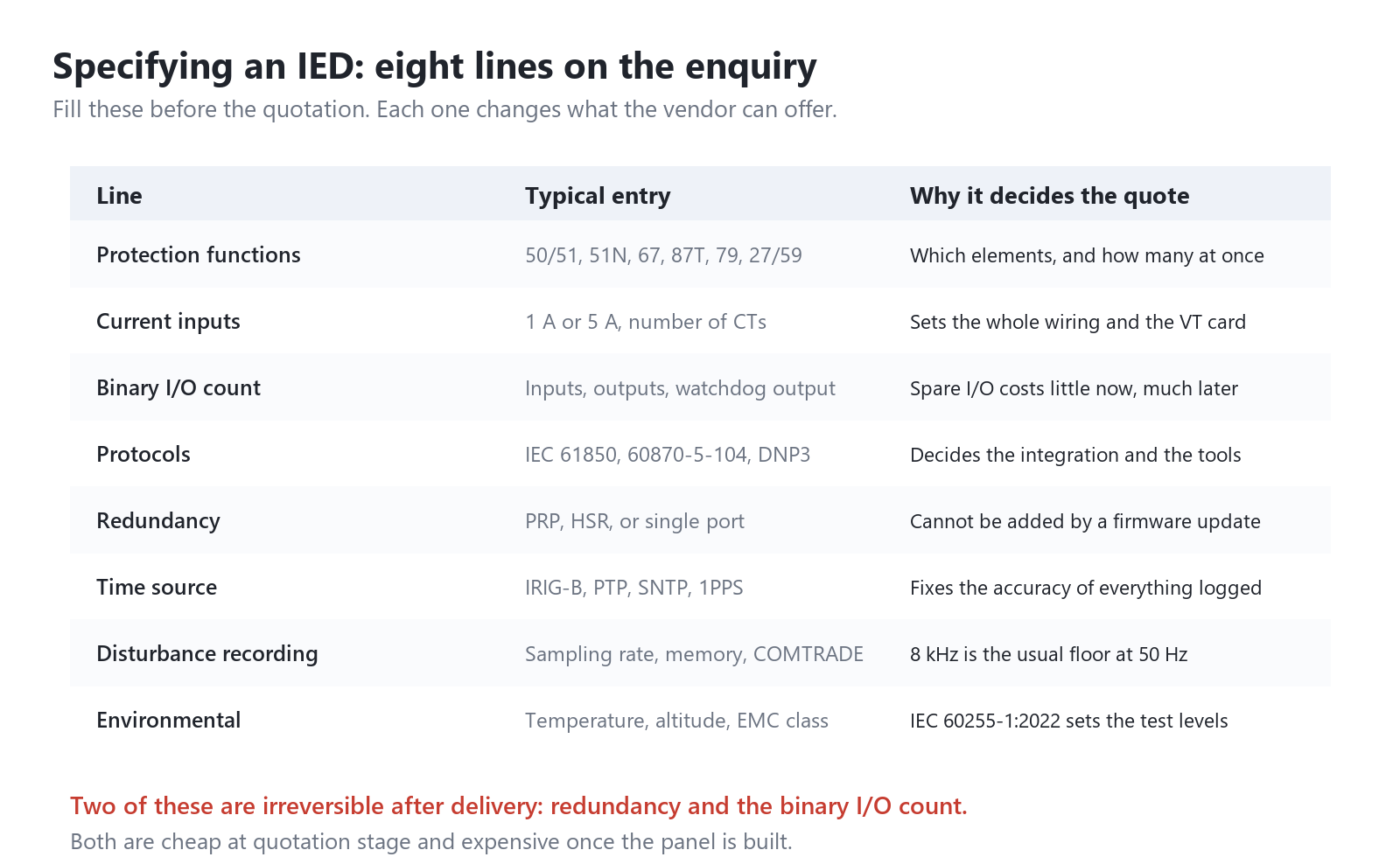
Redundancy comes next, and it is a hardware decision. A device ordered with one Ethernet port cannot join an HSR ring later, whatever the firmware release notes say. The same applies to the number of CT inputs: a two-feeder device cannot become a three-feeder device.
The remaining four lines are protocols, time source, disturbance recording and environment. Environmental class is where export projects go wrong: a device rated to 55 °C in a ventilated cubicle will derate in a pad-mounted enclosure standing in the sun, and IEC 60255-1:2022 asks for the test evidence rather than the claim.
Settings management is the part of an IED project that has no procurement line. A feeder device may hold 400 settings across 30 protection elements, and every one of them can be changed from a laptop in thirty seconds. Ask who holds the master file, how a change is approved, and how a device that has lost its settings is restored from a USB stick at two in the morning. Projects without an answer to that question discover it during the first firmware upgrade.
Ask for the cybersecurity statement too. IEEE 1686-2022 defines what the device should provide: role-based access, an audit trail, signed firmware, and a documented way to disable unused services. A device with telnet open and a default password is a liability that happens to measure current.
When Not to Use an IED
There are real cases where the simpler device is the better engineering choice, and saying so early saves a project.
- A single radial feeder with one overcurrent function and no SCADA: a digital overcurrent relay does the job with a failure mode the maintenance team already understands.
- Ambient above the rated 55 °C with no derating study: the device will run, and its electrolytic capacitors will fail years early.
- No laptop, no test set and no settings archive on site: a device whose configuration nobody can read or restore is worse than a relay with a dial.
- Existing CTs of the wrong class or ratio: a 5P10 CT saturates on the through-fault that a transformer differential function depends on, and the scheme trips on load instead.
- Trip supply mismatch: a 125 V DC trip circuit needs output contacts rated for it, and a solid-state output rated 30 V DC will fail open on the first trip.
- No patch management process: an internet-reachable device that never receives a firmware update accumulates known vulnerabilities for fifteen years.
Selecting a model for this scheme? Send the voltage level, CT/VT ratios and your relay list. An engineer returns a model mapping and quotation within 12 hours →
Commissioning Checks and How These Devices Fail
Field experience across substations produces a short list of failures that repeats, and most of them are caught by four commissioning tests done properly.
| Symptom | Usual cause | What to check |
|---|---|---|
| No trip on a fault, no alarm | Output contact stuck open, or coil circuit broken | Trip circuit supervision and a primary injection to the coil |
| Trips on load | CT secondary reversed or two phases swapped | Phase angle in the measurement display against a known load |
| Differential element unstable | CT saturation on through fault, mismatched class | CT class, knee point, and the actual burden |
| Wrong time order in the event log | Clock drifting after the grandmaster was lost | Time quality flag, and the offset against a portable clock |
| GOOSE signal not received | Subscription missing in the configuration file | The publisher’s dataset against the subscriber’s list |
| Measurement drifting over months | ADC reference ageing, or a failing supply rail | Self-test log for reference and rail alarms |
| Device restarts at random | Auxiliary supply dips during breaker operation | Supply waveform during a trip, not at rest |
Table 4. Seven symptoms that cover most callouts. The first row is the only one where the device gives no warning at all.
Commissioning has to prove the whole loop, not the element. Secondary injection confirms the algorithm and says nothing about the trip coil, the auxiliary contact or the breaker mechanism. Inject into the CT circuit, watch the contact, listen to the breaker, and record the total time.
Prove the loop, not the element.
Two tests are routinely skipped and repeatedly regretted. Replay a COMTRADE file from a real fault through the device and confirm it trips at the same point as the original record. Then pull the auxiliary supply for ten seconds, restore it, and check that the device comes back with the same settings and no unexplained restart in the log.
Frequently asked questions
Is an intelligent electronic device the same as a protection relay?
A protection relay is one function inside the category. The term covers any device with measurement, logic, outputs and communications, including bay controllers, merging units and power quality recorders. A protection relay is the subset whose output is allowed to trip a breaker.
Is a smart meter an intelligent electronic device?
Technically it fits the definition, and in practice the term is not used for meters. The distinction that matters is the trip path: a meter measures and reports, and never decides to open a circuit. Standards written for the category, IEEE 1686-2022 among them, assume the device can trip.
Does an IED replace the RTU in a substation?
Often, yes. A bay device with IEC 61850 or 60870-5-104 can report directly to the control centre and the separate RTU disappears. The exception is a station with many non-intelligent devices, older transducers or a utility that requires a single gateway for security reasons.
How many functions can one device run at once?
Twenty to forty protection elements on a modern feeder device, and the limit is usually the number of CT inputs rather than processor power. Two feeders in one box is common. Three is possible and rarely chosen, because a single failure then removes protection from three circuits at once.
How often should the device be tested?
Every two to four years for protection functions, with a full scheme test after any firmware change or settings change that alters a trip logic path. Self-supervision covers the electronics and says nothing about the CT circuit, the trip coil or the breaker.
What happens when time sync is lost?
Most devices keep running on their own oscillator and flag the time quality. Records taken during that window carry timestamps that are internally consistent and externally wrong, which is worse than no timestamp at all when two devices are being compared. Check the quality flag before trusting any sequence of events.
Can a device from one vendor work with another vendor’s station system?
Yes, if both implement Edition 2 of IEC 61850 and the configuration file is exchanged rather than rebuilt by hand. The interoperability problems that filled the 2010s came from optional data objects and vendor-specific extensions. Ask for a conformance test certificate, and check which edition it was issued against.
Related reading
- Protection relays and how the ANSI elements divide the work
- Substation design and protection at the yard level
- SCADA systems and what the gateway actually collects
- Circuit breakers, the device the trip output drives
Technical references
| Standard or source | What it covers | Edition |
|---|---|---|
| IEC 60255-1 | Common requirements for measuring relays and protection equipment | 2022 |
| IEC 61850-5 | Communication requirements, logical nodes and performance classes | 2013 |
| IEC 61850-8-1 | Mapping to MMS and GOOSE | 2011, amended 2020 |
| IEC 61850-9-2 | Sampled values over the process bus | 2011, amended 2020 |
| IEC 61850-9-3 | Precision time protocol profile for power utilities | 2016 |
| IEEE 1588 | Precision clock synchronisation protocol | 2019 |
| IEC 62439-3 | PRP and HSR redundancy | 2021 |
| IEC 60870-5-104 | Telecontrol over TCP/IP | 2006 |
| IEEE 1686 | Cybersecurity capabilities of an intelligent electronic device | 2022 |
| IEEE C37.2 | Device function numbers and their definitions | 2022 |
Table 5. Editions checked against the publishers in October 2026. The 61850 parts are cited at their base edition year with the 2020 amendments noted.
Field record
Every relay we have supplied since the earliest projects in this record is an IED with at least one communication port. The protocols it has to speak are set by the client, and our record covers the spread: IEC 61850 in a 3 MW PV plant in Hebei and a 33 kV substation automation system in Iraq, Modbus into plant SCADA in Laos and Oman, and DNP3 or IEC 60870-5-104 where the utility dispatch expects it. Plants and voltages by country: project record.
Conclusion
An intelligent electronic device is best understood as a concentration of functions that used to be separate boxes, and every advantage it brings comes from that concentration. Fewer wires, one settings file, one clock, one record. The cost is a single point of failure that covers all of it, and a device whose behaviour lives in data rather than in copper.
Specify the hardware that cannot be changed later first: CT inputs, binary I/O, redundancy, output contact rating. Then settle protocols and time sync, because those decide how the device fits a system that already exists. Leave the function list to last, since it is the only part that can genuinely be revised after the order.
If you are weighing a device against a panel of discrete relays for a specific feeder, send the single-line and the CT details. The answer usually turns on the burden and the trip circuit, not on the processor.
Related: Substation Auxiliary Equipment
Related: SCADA software
Working on a similar scheme? Send the single-line diagram, relay list and CT/VT data. Quote in 12 hours →
About Author

Hello, I'm Leon Zhang. I have 15 years of experience in the power relay protection industry with extensive pre-sales and after-sales project experience. Our company specializes in various complete sets of relay protection and automation equipment. I can assist customers in solving all practical on-site project challenges and provide optimal integrated solutions.
Tell Us Your Requirement



High Quality
Stable performance, reliable design, ensuring safe operation for power system protection and grid stability.
Fast Delivery
Timely delivery to support your urgent orders and project schedules efficiently and professionally at any time.
Best Warranty
Professional Warranty: Reliable after-sales support for stable relay protection and long-term customer satisfaction.