

-
Leon Zhang sales consultant
-
Email: zxl635973785@gmail.com
-
Phone/WhatsApp: +86 13655813266
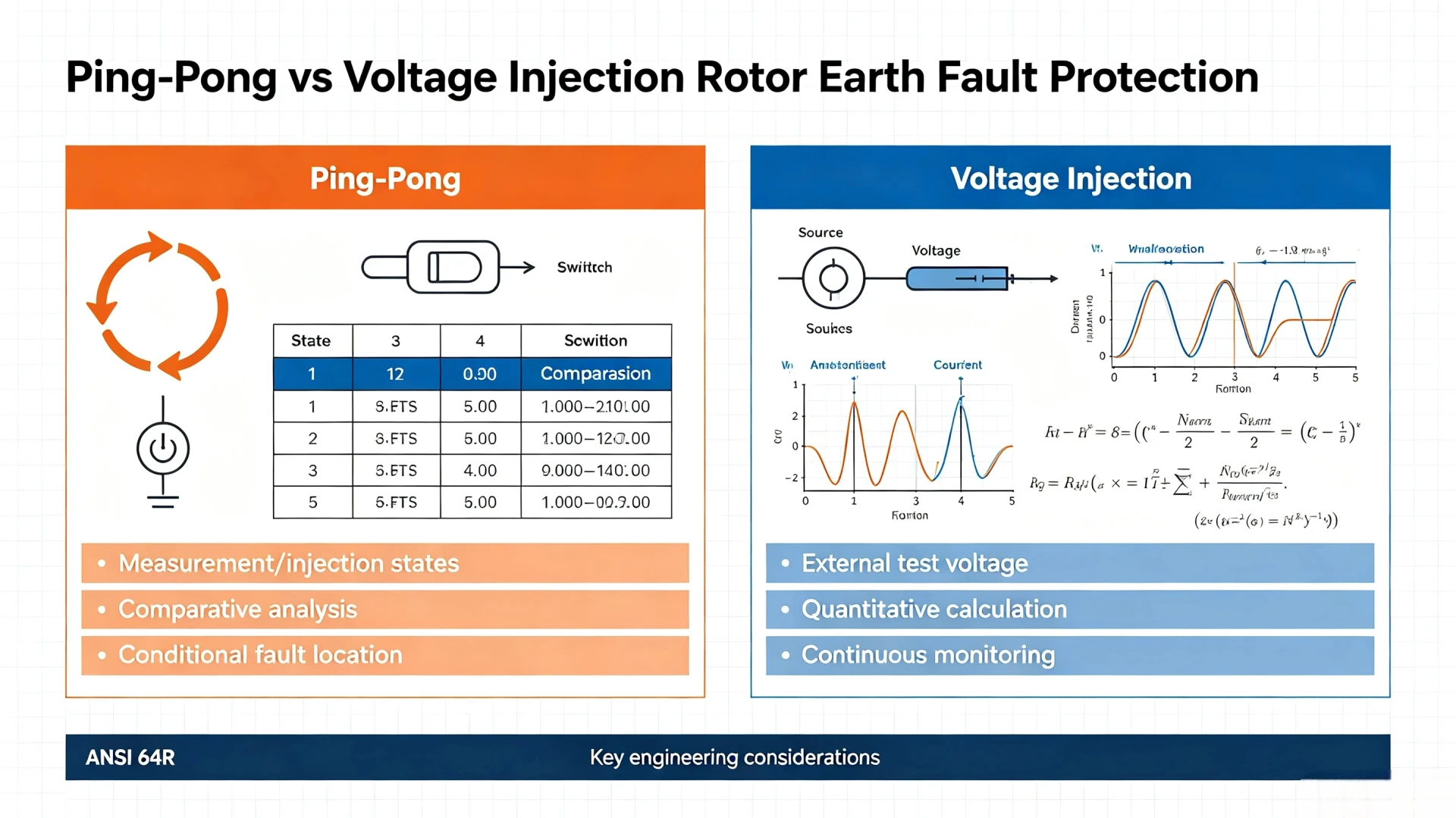
Ping-Pong vs Voltage Injection Rotor Earth Fault Protection: Which Method Is Better?
Rotor earth fault protection is a critical 64R protection function for synchronous generators, designed to detect insulation degradation and earth faults in field windings. The rotor circuit of a healthy generator is fully isolated from ground; a single earth fault does not form a high-current fault loop and will not trigger immediate trip action, but a second subsequent earth fault will create short-circuit damage to rotor windings, shafts and excitation systems.
In global power EPC projects, two mainstream technical schemes dominate 64R rotor earth fault protection: Ping-Pong measurement scheme and voltage injection scheme. Both implement rotor insulation monitoring and fault detection, but they differ fundamentally in working principles, functional boundaries, system compatibility and application scenarios.
For power plant owners, EPC engineers and protection commissioning teams, the core concern is not which method is universally superior, but which scheme matches the specific generator type, excitation configuration and protection requirements.
This article compares the two industrial-standard methods from first principles, technical differences, field application boundaries and engineering selection criteria, providing a practical decision-making framework for 64R protection scheme design, new project bidding and old system retrofit.
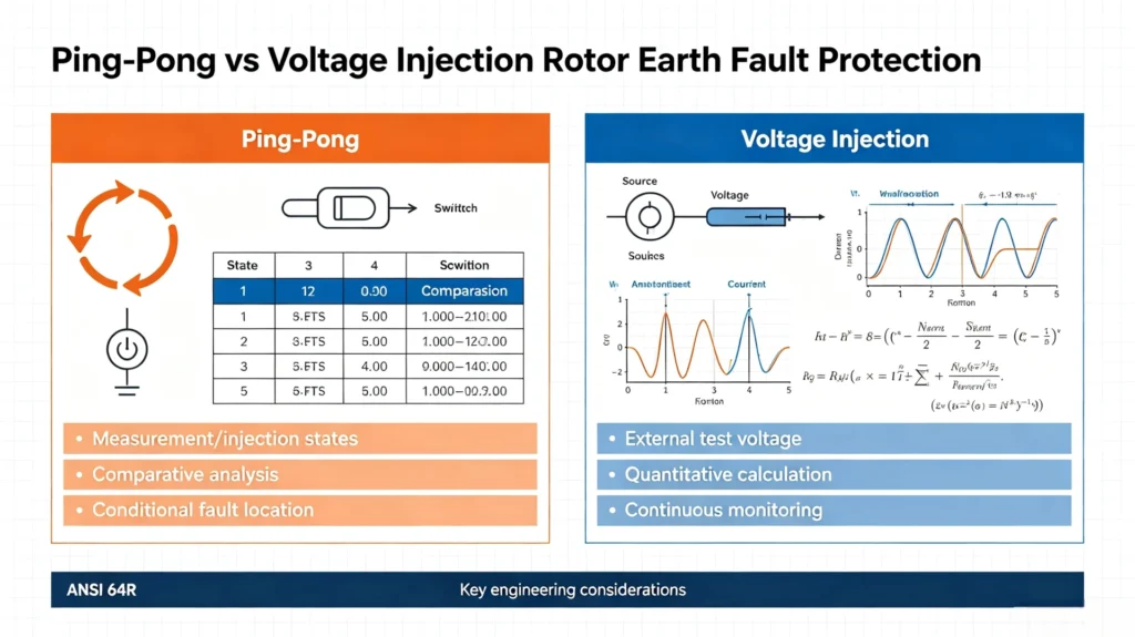
Quick Answer: Ping-Pong vs Voltage Injection Rotor Earth Fault Protection
Ping-Pong and voltage injection are two mature approaches to 64R rotor earth fault detection for synchronous generators. The voltage injection method applies a continuous controlled test signal to the rotor circuit and evaluates current, voltage and impedance responses to monitor rotor-to-ground insulation status. The Ping-Pong scheme alternates measurement or injection circuit states and compares data from multiple working conditions to identify insulation faults. The applicability of each method depends on generator structure, excitation system type, required monitoring functions and existing plant protection architecture.
| Aspect | Ping‑Pong | Voltage Injection |
|---|---|---|
| Basic Principle | Alternate measurement/injection states for comparative analysis | Controlled external test‑voltage signal injection |
| Core Functions | Fault detection and conditional fault location | Real‑time insulation monitoring and fault detection |
| Measurement Basis | Electrical response comparison under different circuit states | Quantitative calculation based on V/I and impedance parameters |
| On‑line Monitoring | Scheme‑dependent on manufacturer’s design | Typically designed for full on‑line continuous monitoring |
| ANSI 64R Compliance | Fully compliant with ANSI 64R requirements | Fully compliant with ANSI 64R requirements |
| Key Engineering Considerations | Rotor circuit switching logic and compatibility | Injection signal coupling and excitation system isolation |
What Is Rotor Earth Fault Protection (ANSI 64R)?
Why Rotor Earth Fault Protection Is Mandatory
Synchronous generator rotor field windings operate in a fully floating, ungrounded state during normal service. A single rotor earth fault only creates a potential grounding point without forming a closed fault loop, resulting in negligible fault current and no immediate equipment damage.
However, if a second earth fault occurs at a different position of the rotor winding, it will form a short-circuit loop, causing local overheating, winding burnout, rotor magnetic field distortion, and even unit vibration and shaft current damage. Rotor earth fault protection is designed to capture early insulation degradation and single-point faults, providing early warning and preventing secondary catastrophic faults.
Definition of ANSI 64R Protection
ANSI 64R is the industry standard designation for Rotor Earth Fault Protection, also known as field ground fault protection or rotor insulation monitoring. It covers all relay-based schemes that monitor the insulation status between generator rotor windings and ground, applicable to hydroelectric generators, turbo-generators and other synchronous power generation units.
Core Monitored Parameters of 64R Relays
Modern digital 64R relays do not rely on single data judgment; they integrate multiple electrical parameters to evaluate rotor insulation health status:
| Monitored Parameter | Engineering Purpose |
|---|---|
| Rotor-to-ground voltage | Reflects overall insulation balance and potential offset |
| Leakage current | Identifies conductive grounding paths and insulation damage |
| Insulation resistance/impedance | Quantifies insulation aging degree and degradation trend |
| Fault status signal | Triggers graded alarm and trip protection logic |
How Does Ping-Pong Rotor Earth Fault Protection Work?
The Ping-Pong scheme is a state-comparison-based 64R protection method. Unlike fixed-measurement schemes, it completes fault judgment through multiple state switching and data comparison, with core advantages in anti-interference and conditional fault location capability.
Basic Working Principle
The core logic of the Ping-Pong method is multi-state circuit switching and differential comparison. The relay actively switches the measurement or injection circuit between two independent working states, collects electrical data under each state, and eliminates system interference through data difference analysis to accurately identify rotor earth faults.
It is inaccurate to simply define this method as polarity switching. Different relay manufacturers adopt differentiated circuit design and switching logic, but all follow the core rule of “comparative measurement under different circuit conditions”.
Dual-State Measurement Logic
State A (Basic Measurement State): The relay locks the initial circuit configuration, conducts real-time sampling of rotor-to-ground voltage, leakage current and insulation impedance, and records the baseline operating data of the healthy rotor circuit.
State B (Switched Measurement State): The relay automatically switches the internal measurement/injection loop, changes the circuit operating conditions, and repeats the same data sampling process.
Fault Judgment Mechanism
The relay completes fault identification through logical comparison: State A baseline data → State B switched data → differential calculation → interference filtering → fault threshold judgment.
When the rotor insulation is intact, the data difference between the two states is stable within the normal range; when insulation degradation or earth fault occurs, the electrical response difference changes significantly, which the relay captures to trigger protection signals.
Fault Location Capability Explanation
A key professional distinction of the Ping-Pong scheme is its conditional fault location function, but this capability is not universal.
High-end digital Ping-Pong 64R relays can calculate the approximate fault position of the rotor winding through multi-state data fitting and algorithm analysis. However, location accuracy and availability depend entirely on the relay hardware design, algorithm optimization and rotor circuit structure. Basic Ping-Pong schemes only support fault detection without location function.
It is critical to distinguish: fault detection ≠ fault location in engineering applications.
How Does Voltage Injection Rotor Earth Fault Protection Work?
Voltage injection is a signal-active quantitative monitoring scheme, which is the most widely used 64R protection method in new power plant projects. It realizes full-cycle online monitoring of rotor insulation status through external test signal injection.
Test Signal Generation and Injection
The built-in signal source of the 64R relay generates stable, controllable AC test voltage signals (parameters optimized according to generator field voltage levels). The signal is coupled into the generator rotor field circuit through a dedicated isolation and coupling loop, forming a complete measurement loop of “injection source – rotor winding – insulation medium – ground”.
Multi-Dimensional Electrical Response Measurement
After signal injection, the relay synchronously samples multiple core parameters: loop current, signal phase difference, rotor-to-ground voltage and loop impedance. Different from simple resistance calculation, industrial relays filter out excitation system ripple, high-frequency interference and ambient noise through digital signal processing algorithms.
Insulation Status Evaluation and Protection Logic
The relay calculates real-time rotor insulation resistance based on optimized V/I relational formulas and phase compensation algorithms. Combined with preset threshold parameters, it forms graded protection logic: normal insulation status → slight degradation warning → confirmed earth fault alarm → trip output (if configured).
This scheme supports continuous online monitoring, can capture slow insulation aging trends in real time, and is more suitable for long-term stable operation monitoring of large generators.
Ping-Pong vs Voltage Injection: Core Technical Differences
The following table summarizes the key technical differences between the two schemes from engineering application dimensions, covering principle, function, compatibility and maintenance features, providing direct support for scheme selection:
| Technical Aspect | Ping-Pong Scheme | Voltage Injection Scheme |
|---|---|---|
| Measurement Principle | Multi-state switching comparison measurement | Active test signal injection + quantitative calculation |
| Core Monitoring Advantage | Strong anti-interference, suitable for complex electromagnetic environments | High measurement accuracy, stable continuous monitoring |
| Fault Detection | Full support for high and low resistance faults | Full support for high and low resistance faults |
| Fault Location Function | Supported in high-end schemes | Rarely supported, dependent on customized algorithms |
| Continuous Online Monitoring | Partial scheme support | Standard full-cycle online monitoring |
| Excitation System Compatibility | Need to verify switching loop compatibility | Need to verify signal coupling isolation |
| Installation Requirements | Simpler wiring, no dedicated injection loop | Requires professional coupling and wiring configuration |
| Commissioning Focus | State switching logic and data consistency verification | Injection signal stability and threshold calibration |
Available Monitoring Information of Each Scheme
Fault Detection Capability
Both schemes fully meet ANSI 64R standard fault detection requirements and can effectively identify instantaneous earth faults and persistent grounding faults of rotor windings. There is no essential gap in basic fault protection capability.
Insulation Resistance Trend Monitoring
The voltage injection scheme excels in continuous trend monitoring. It can output real-time insulation resistance values and form long-term change curves, helping operation teams capture early slow insulation aging.
Most Ping-Pong schemes focus on fault judgment, with relatively weaker continuous quantitative monitoring capability, suitable for fault-triggered protection scenarios.
Fault Location vs Fault Detection
This is the core professional differentiation point of the two schemes. Detection only confirms the existence of a rotor earth fault; location can feed back the approximate fault winding position. For routine power plant protection, detection is sufficient; for unit overhaul, fault location can greatly improve maintenance efficiency.
Fault Severity Identification
Both schemes can identify high-resistance intermittent faults and low-resistance permanent faults. Combined with relay historical data, they can judge fault deterioration trends and support predictive maintenance.
Scheme Adaptability for Different Generator Scenarios
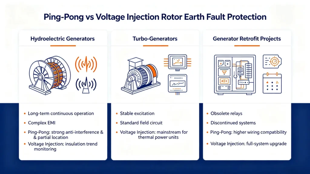
Hydroelectric Generators
Hydro units feature long-term continuous operation, complex on-site electromagnetic interference and high requirements for fault troubleshooting. Ping-Pong schemes with strong anti-interference and partial location functions are widely applicable; voltage injection schemes are also suitable for units requiring long-term insulation trend monitoring.
Turbo-Generators
High-speed turbo-generators have stable excitation systems and standard field circuit designs. Voltage injection schemes with stable online monitoring performance are the mainstream selection, matching the precise monitoring requirements of thermal power units.
Generator Retrofit Projects
Most overseas EPC retrofit projects face scenarios such as obsolete old relays, discontinued protection systems and mismatched excitation systems. The Ping-Pong scheme has higher wiring compatibility and fewer transformation works, suitable for limited shutdown windows and old cabinet renovation scenarios. The voltage injection scheme is more suitable for full-system upgrade projects pursuing long-term monitoring performance.
Engineering Selection Framework: How to Choose the Suitable 64R Scheme
No universal “best” rotor earth fault protection scheme exists. The optimal solution is determined by multiple on-site engineering factors. The following decision framework guides standardized scheme selection:
1. Select Based on Rotor Field Circuit Configuration
Confirm generator rated field voltage, field current, winding structure and floating grounding design. Special rotor circuit designs need to verify the switching adaptability of Ping-Pong schemes and the signal coupling stability of voltage injection schemes.
2. Select Based on Excitation System Type
Static excitation, brush excitation and brushless excitation systems have different loop characteristics. It is necessary to exclude signal interference between the 64R protection scheme and the excitation regulation loop to avoid false alarms and missing detection.
3. Select Based on Functional Requirements
Only basic fault alarm and trip functions: both schemes are available. Requiring long-term insulation trend monitoring: priority to voltage injection. Requiring rapid fault location to reduce maintenance time: priority to high-end Ping-Pong schemes.
4. Select Based on Existing Plant Protection Architecture
The new 64R relay needs to be compatible with the existing generator protection panel, DCS and SCADA communication protocols to ensure data interconnection and unified plant protection logic.
5. Select Based on Retrofit and Construction Constraints
Evaluate on-site panel space, reserved wiring ports, unit shutdown maintenance cycle and construction difficulty to select the scheme with the highest construction feasibility.
Online Monitoring and Maintenance Application Comparison
It is necessary to clarify that online rotor earth fault protection cannot replace offline insulation withstand voltage tests. Online monitoring is used for real-time operation risk warning, while offline tests are the standard basis for equipment overhaul and acceptance.
| Function Item | Ping-Pong | Voltage Injection |
|---|---|---|
| Real-time online fault detection | Scheme dependent | Standard support |
| Continuous insulation trend monitoring | Partial support | Full support |
| Regular maintenance test substitution | Not substitutable | Not substitutable |
| Offline insulation test dependence | Required periodic testing | Required periodic testing |
Protection Setting and Commissioning Specifications
Core Setting Principles
There is no universal standard parameter template for 64R protection settings. All threshold values, delay time and filtering parameters must be adjusted according to generator manufacturer data, field circuit parameters, on-site interference environment and commissioning test results.
Unified Field Commissioning Steps
Both schemes follow the same standard commissioning process for overseas EPC projects:
- 1. Review generator and protection system drawings
- 2. Verify rotor field circuit integrity and insulation status
- 3. Check relay wiring correctness and grounding reliability
- 4. Test measurement/injection loop stability
- 5. Simulate rotor earth fault conditions with professional test equipment
- 6. Calibrate measured data accuracy
- 7. Complete alarm function test
- 8. Verify trip output logic (configured projects) 9. Debug communication data upload to DCS/SCADA
Common On-Site Engineering Problems
Causes of 64R Relay False Alarms
False alarms are mostly caused by on-site environmental and wiring problems: irregular shielding grounding, excitation system signal interference, unstable measurement loop contact, unreasonable threshold setting, and early insulation micro-degradation of rotor windings.
Unstable Insulation Measurement Data
Main influencing factors: on-site electromagnetic interference, loose wiring terminals, inconsistent grounding potential and unoptimized relay filtering parameters. It can be solved by parameter calibration and wiring rectification during commissioning.
Fault Detection Valid but Location Failed
Most low-end 64R protection schemes only retain detection functions and simplify location algorithms. Fault location is an extended customized function rather than a standard matching function of 64R protection.
Rotor Earth Fault Protection Selection Checklist (Decision Matrix)
This checklist provides standardized judgment basis for EPC design and owner engineering review, avoiding arbitrary scheme selection:
| Selection Question | Key Engineering Consideration |
|---|---|
| Generator type | Hydroelectric / Turbo / Synchronous generator structural characteristics |
| Excitation system type | Static / Brush / Brushless excitation compatibility verification |
| Online monitoring demand | Whether long-term continuous insulation trend monitoring is required |
| Fault location demand | Distinguish mandatory location requirement and basic detection requirement |
| Protection output type | Alarm only / Alarm + Trip dual output |
| Project type | New construction / Old system retrofit (constraint difference) |
| Communication requirement | Modbus / RS-485 / SCADA system docking specification |
| Measurement range requirement | Match relay insulation resistance measurement range with unit parameters |
FAQ
1. What is the core difference between Ping-Pong and voltage injection rotor earth fault protection?
The core difference lies in the measurement logic. Ping-Pong relies on multi-state switching comparison to judge faults with strong anti-interference; voltage injection relies on active signal injection for quantitative monitoring with higher continuous measurement accuracy.
2. Are both methods compliant with ANSI 64R standards?
Yes. Both schemes fully meet the functional requirements of ANSI 64R rotor earth fault protection and are industrial-standard mainstream solutions.
3. Can both schemes detect single rotor earth faults?
Yes. Both can effectively identify single-point insulation faults and early degradation, preventing secondary short-circuit faults.
4. Is fault location function available for all 64R relays?
No. Fault location is an extended function, mostly supported by high-end Ping-Pong scheme relays, while most voltage injection devices only support fault detection.
5. Can 64R protection operate during generator full-load operation?
Yes. Both online schemes support normal operation monitoring of generators without affecting unit power generation and excitation system operation.
6. Which scheme is more suitable for retrofit projects?
Ping-Pong schemes have simpler wiring and lower transformation difficulty, more suitable for old plant retrofits; voltage injection schemes are more suitable for new projects pursuing long-term monitoring performance.
7. Which scheme has higher measurement accuracy?
Voltage injection schemes have advantages in continuous quantitative measurement accuracy; Ping-Pong schemes have better stability in complex electromagnetic interference environments.
8. How to determine the final 64R protection scheme?
The final selection needs to comprehensively consider generator type, excitation configuration, functional demand, project type and on-site construction conditions, without single-dimensional superiority judgment.
Conclusion
Ping-Pong and voltage injection rotor earth fault protection are two complementary 64R technical schemes with no absolute superior or inferior performance. The Ping-Pong method features strong anti-interference and conditional fault location capability, adapting to complex working conditions and retrofit scenarios. The voltage injection method provides stable continuous insulation monitoring and quantitative data output, more suitable for new power plants and high-precision operation monitoring scenarios.
For overseas power EPC, owner operation and maintenance teams, standardized scheme matching based on on-site engineering conditions is the core of 64R protection design. Reasonable scheme selection can effectively improve generator rotor insulation monitoring reliability, reduce equipment failure risks, and extend the service life of synchronous generator units.
For new generator protection projects and 64R system retrofits, select a matched rotor earth fault protection relay according to generator parameters and excitation system characteristics to ensure long-term stable operation of unit protection systems.
Technical Reference & Data Source
1. ANSI/IEEE C37.102-2019: Guide for Generator Protection 2. IEC 60034-27: Rotor Insulation Monitoring Standards for Synchronous Machines 3. International Power Plant Protection System Engineering Specifications 4. Official technical manuals of mainstream 64R protection relays 5. Field commissioning test data of overseas generator protection EPC projects



About Author

Hello, I'm Leno Zhang. I have 15 years of experience in the power relay protection industry with extensive pre-sales and after-sales project experience. Our company specializes in various complete sets of relay protection and automation equipment. I can assist customers in solving all practical on-site project challenges and provide optimal integrated solutions.
Tell Us Your Requirement
High Quality
Stable performance, reliable design, ensuring safe operation for power system protection and grid stability.
Fast Delivery
Timely delivery to support your urgent orders and project schedules efficiently and professionally at any time.
Best Warranty
Professional Warranty: Reliable after-sales support for stable relay protection and long-term customer satisfaction.