
-
Leon Zhang sales consultant
-
Email: zxl635973785@gmail.com
-
Phone/WhatsApp: +86 13655813266
Power Relay: Types, Ratings, Selection Guide and Applications
A power relay is an electrically operated switch built to control loads that exceed the capability of signal-level relays. Choosing the correct power relay for an industrial application comes down to seven inputs taken together—coil voltage, contact voltage rating, continuous current, AC/DC load type, inrush current, switching frequency and required electrical life—and the maximum current printed on the datasheet is the least reliable of the seven.
For EPC contractors and project engineers, relay failures in the field almost always trace to one of three causes: selecting by nominal current instead of load category, ignoring inrush current, or confusing coil voltage with contact voltage. This guide addresses each.
Key Takeaways
- A relay of this class switches 3 A to 30 A or more, while a signal-level device switches below 2 A and is optimised for signal integrity rather than load capacity.
- Coil voltage and contact voltage are independent specifications. A 24 V DC coil can drive contacts that switch a 230 V AC load.
- The IEC 60947-4-1:2023 utilization category, not the headline amp figure, sets the usable current. A relay rated 25 A in AC-1 may carry only 8.5 A in AC-3 (see protection relay selection for the panel-level view).
- Motor inrush runs 5–10× steady state. A 5 A motor presents roughly 50 A to the contacts at every start.
- Contact welding—not coil burnout—is the dominant field failure mode, and it traces back to selection rather than to the relay itself.
- Electrical life is typically two to three orders of magnitude below mechanical life, and switching rate decides which one binds first.
What Is a Relay of This Class and How Does It Work?
A power relay uses an electromagnetic coil to mechanically actuate one or more sets of electrical contacts, and the coil circuit stays electrically isolated from the contact circuit so that a low-power control signal can command a much larger load. Energising that coil, typically at 12 V DC, 24 V DC or 230 V AC, moves an armature that closes or opens the load contacts.
Power relays differ from signal relays in contact design and load capability rather than in basic principle. Signal relays switch currents under 2 A and are optimised for low-level signal integrity. Power relays switch from 3 A to 30 A or more, with contacts sized for higher current density and for arc management.
| Parameter | Signal Relay | Power Relay |
|---|---|---|
| Typical current rating | Below 2 A | 3–30 A (general purpose) |
| Typical voltage rating | 5–30 V DC | Up to 440 V AC / 150 V DC |
| Contact material | Gold-plated, low-level | Silver alloy, arc-resistant |
| Coil power consumption | Around 100 mW | Around 400 mW or higher |
| Primary application | Signal integrity | Load switching |
The distinction matters in both directions. Using a load-switching relay for signal switching can corrupt low-level signals, because power relay contacts often carry an anti-corrosive coating that introduces resistance above 100 Ω until the contacts are broken in by actual load current.
Coil Voltage vs Contact Voltage: Two Independent Specifications
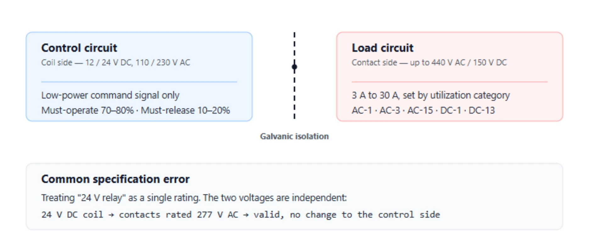
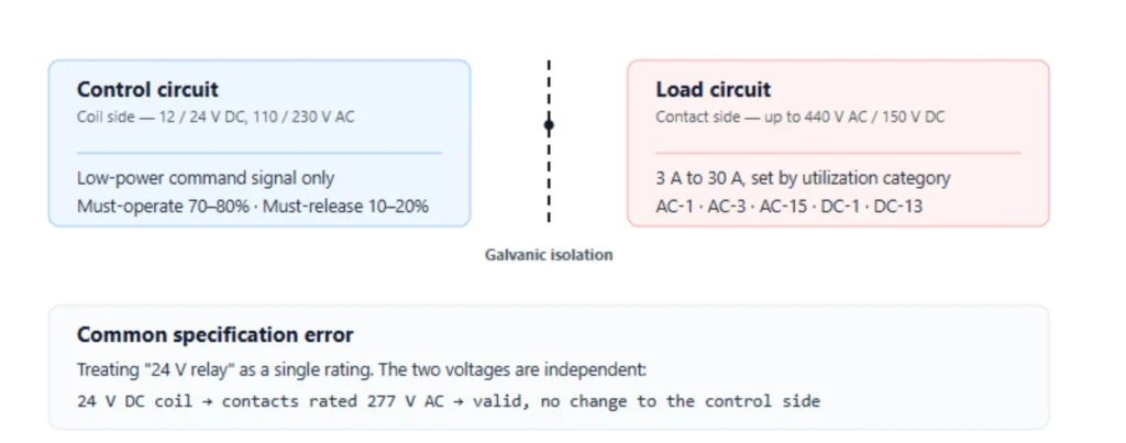
A common specification error is treating “24 V relay” as a single rating, when coil voltage and contact voltage are separate parameters that must each be verified against their own circuit. The coil side belongs to the control circuit; the contact side belongs to the load circuit, and the two need not share a voltage, a supply or even a current type.
A signal relay is a low-level switching device rated below 2 A, optimised for contact integrity rather than load capacity.
Coil voltage is the control circuit supply. Common values are 5 V DC, 12 V DC, 24 V DC, 110 V AC and 220–230 V AC. The coil must receive voltage within its operating range, typically from eight tenths to slightly above nominal, to guarantee actuation across the full ambient temperature range as defined in IEC 61810-1:2015 coil operating conditions.
An electromechanical relay is a device that moves physical contacts by electromagnetic force, which means it carries a mechanical life separate from its electrical life.
Contact voltage is the load circuit voltage, and it can be entirely different from the coil voltage. A 24 V DC coil relay with appropriately rated contacts can switch a 230 V AC or 277 V AC load without any change to the control side.
[PERSONAL EXPERIENCE] On a returned batch of panel relays, the coils all tested within tolerance on a bridge while the contacts had welded in the closed position—confirming that the failure mode traced to load switching rather than to the control circuit, and that a coil test alone cannot clear a suspect relay for reuse.
Coil Operating Characteristics
Relay coils have defined voltage thresholds that determine reliable operation, and a control circuit designed against the nominal figure alone can sit inside the sag band without anyone noticing until a panel fails to start.
- Must-operate voltage: the minimum coil voltage at which the relay will actuate, typically 70% to 80% of nominal (IEC 60947-5-1:2024 control circuit device thresholds).
- Must-release voltage: the maximum voltage at which the relay will definitely drop out, typically 10% to 20% of nominal (IEC 60947-5-1:2024 control circuit device thresholds).
- Maximum voltage: the highest continuous coil voltage the relay withstands without damage.
A control circuit that supplies 24 V nominal but sags to 20 V during operation may fall below the must-operate threshold of a 24 V relay. Verify the operating range, not just the nominal rating.
Contact Rating: Why “30 A” Is Not a Universal Number
The current rating printed on the datasheet applies to one specific combination of load category, voltage and switching frequency, and changing any one of the three changes the usable current with it. This is why two relays that both claim 30 A can behave completely differently on the same motor, and why the headline figure alone cannot answer a selection question.
AC vs DC Contact Ratings
AC and DC contact ratings are not interchangeable, and the difference is physical rather than commercial. AC arcs extinguish at current zero crossings, which occur 100 or 120 times per second at 50/60 Hz, whereas DC arcs have no natural zero crossing and require either a relay specifically rated for DC loads or external arc suppression fitted across the contacts.
A relay rated 20 A at 277 V AC may carry only a fraction of that current at 30 V DC. One widely used general-purpose model illustrates the gap: 20 A at 220 V AC resistive, but the same relay requires special precautions above 30 V DC.
Load Category Derating
The IEC 60947-4-1:2023 utilization categories define contact derating for different load types, and they are the reason a single ampere figure cannot describe a relay’s real capacity:
| Category | Load Type | Typical Derating from AC-1 |
|---|---|---|
| AC-1 | Resistive (heaters, lamps) | Reference, full rating |
| AC-3 | Squirrel-cage motor start/stop | Derate to five to seven tenths of rated current |
| AC-15 | Solenoids, contactors | Derate to four to six tenths of rated current |
| DC-1 | Resistive DC | Depends on voltage |
| DC-13 | DC electromagnets | Derate to three to five tenths of rated current |
A relay rated 25 A in AC-1 may be rated only 8.5 A in AC-3 for motor control. Specifying by the AC-1 number for a motor application produces contact welding or accelerated erosion, and the relay is usually blamed rather than the selection. The same derating logic appears in motor protection relay setting calculation, where the overload curve is matched to the same load category.
Inrush Current: The Most Common Cause of Premature Relay Failure
Inrush current is the transient current that flows for a few milliseconds when a load is first energised, and for inductive and capacitive loads it can reach many times the steady-state running current. It arrives within the first few milliseconds, precisely when the contacts are still closing and the conducting area is at its smallest, which is why inrush rather than running current so often determines whether a relay survives the application.
| Load Type | Inrush Ratio (Peak / Steady-State) |
|---|---|
| Resistive | 1× |
| Relay coil | 2–3× |
| Motor | 5–10× |
| Solenoid | Around 10× |
| Incandescent lamp | 10–15× |
| Capacitor | 20–50× |
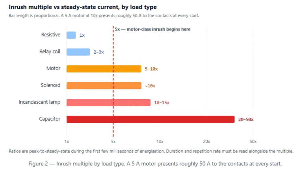
A 5 A motor with a 10× inrush ratio presents 50 A to the relay contacts at start. If the relay’s contact rating is based on resistive load, the contacts must absorb this surge. The result is often dynamic contact welding—the contacts fuse together during closure and fail to open on the next signal.
[ORIGINAL DATA] At 100,000 electrical operations, a load switched once per minute reaches end of life in 69 days, while the same load switched ten times per day lasts 27 years—a 143-fold difference in service interval from the switching rate alone, with the relay model held constant.
Evaluating Inrush for Relay Selection
Three values determine inrush compatibility, and a datasheet that gives only the steady-state figure leaves all three unanswered:
1. Peak current — the maximum instantaneous current at startup 2. Duration — how long the inrush lasts, typically 0.1–2 seconds for motors 3. Repetition rate — how often the load starts
The relay datasheet must specify a maximum inrush current rating, not just a steady-state current rating. One general-purpose model in common use lists 60 A maximum inrush alongside its 20 A continuous rating—a threefold gap that matters more than the continuous figure.
Switching Frequency and Electrical Life
Electrical life is specified in operations at a defined load, and mechanical life is specified with no load applied at all, so the two numbers published for the same relay differ by orders of magnitude and are not interchangeable when quoting service intervals. Quoting the wrong one is a reliable way to promise a panel lifetime the relay cannot deliver, and the error only becomes visible in the field after several months of service.
A typical unit in this class may have 10 million mechanical operations but only 100,000 electrical operations at rated load. High inrush or inductive loads reduce electrical life further.
When Electrical Life Becomes the Limiting Factor
At an electrical life of 100,000 cycles, the switching rate alone decides the calendar lifetime, and the arithmetic is unforgiving:
| Switching Rate | Electrical Life at 100,000 Cycles |
|---|---|
| 10 per day | Around 27 years |
| 1 per minute | Around 69 days |
| 10 per minute | Around 7 days |
If the application switches more than a few times per hour under load, solid state relays or contactors designed for high-cycle duty should be evaluated. Zero-cross switching, which closes contacts at the AC voltage zero crossing, can extend relay life for AC loads by reducing inrush stress. For panels where the relay sits inside a wider protection scheme, the coordination rules in protection of switchgear set the boundary between switching duty and fault duty.
Contact Configuration
Standard contact configurations follow IEC 60947-5-1:2024 terminology, where the form letter describes the contact arrangement and the default state describes what the contacts do while the coil remains de-energised and no control signal is present. Reading both together is what tells a designer whether a circuit fails open or fails closed when control power is lost, which is a safety decision rather than a wiring preference:
| Form | Symbol | Default State | Operation |
|---|---|---|---|
| Form A | SPST-NO | Open | Closes on energisation |
| Form B | SPST-NC | Closed | Opens on energisation |
| Form C | SPDT | COM-NC closed | Transfers COM to NO |
Multiple poles (DPST, DPDT) switch two independent circuits simultaneously. Normally closed contacts are used for fail-safe logic: if control power is lost, the NC contact closes, activating an alarm or shutdown circuit.
Power Relay vs Contactor: When to Use Which
A contactor is a heavy-duty switching device designed specifically for high-power motor loads, and the distinction between a contactor and a comparable relay is not simply the current rating printed on the front of each device. It is contact design, arc suppression and duty rating taken together, which is why a compact 30 A relay and a 30 A contactor rated at the same current are not interchangeable in a motor branch circuit and should never be substituted for one another on price.
| Factor | Power Relay | Contactor |
|---|---|---|
| Typical current | 3–30 A | 9–800 A and above |
| Arc suppression | Limited | Arc chutes, magnetic blowout |
| Motor rating | Limited | AC-3, AC-4 rated |
| Auxiliary contacts | Integral or plug-in | Add-on blocks |
| Size | Compact, PCB or DIN mount | Larger, panel mount |
A relay can replace a contactor only if it carries an explicit motor horsepower or AC-3 rating. Most general-purpose relays do not, and the omission is deliberate rather than an oversight. Where a protection function is also required, the device selection logic in what are protective relays explains how the switching element and the sensing element are kept separate.
Protection Against Inductive Switching Stress
Inductive loads store energy in a magnetic field while current flows through them, and when the relay contacts open that stored energy discharges as a voltage spike across the parting gap between the contacts. The spike can exceed the relay’s dielectric rating and sustain an arc across the parting contacts, which erodes contact material and shortens life, so suppression is a design requirement rather than an optional refinement on any circuit that switches coils, solenoids or motor windings.
DC loads: a flyback diode across the load provides a circulating path for the inductive current, collapsing the voltage spike below the arc threshold.
AC loads: an RC snubber or metal-oxide varistor across the contacts limits dV/dt and absorbs the inductive kick.
Suppression components reduce switching stress but do not compensate for a relay that is underrated for the load. Protection is not a substitute for correct selection.
What Should You Include in a Power Relay RFQ?
The following information allows a supplier to recommend a relay based on actual load conditions rather than on a guessed current rating, and every line corresponds to a decision the supplier would otherwise have to make on your behalf. Omitting any single line transfers that decision to the supplier, who cannot see the panel, the load or the duty cycle:
- Application and duty description
- Coil / control voltage
- Load voltage
- AC or DC load
- Continuous load current
- Load type (resistive / inductive / motor)
- Inrush current and duration
- Switching frequency
- Contact configuration (NO / NC / CO)
- Required electrical life
- Ambient temperature
- Mounting (PCB / DIN rail / panel)
- Quantity
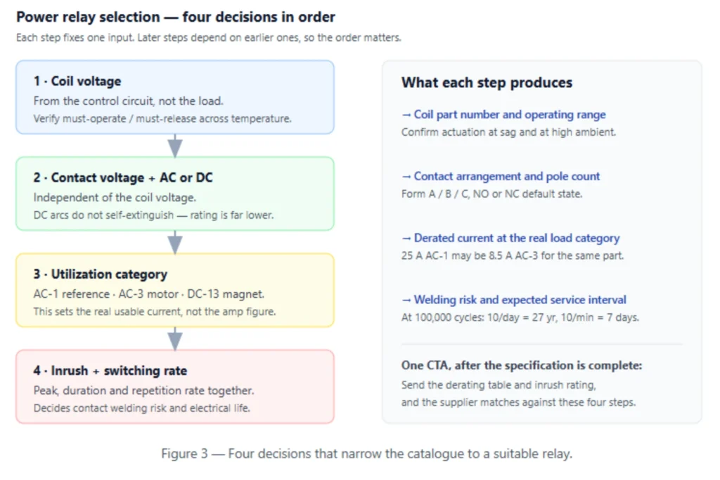
A request for a 30 A device is insufficient because it omits load voltage, AC/DC type, load category and inrush current. A relay that meets the resistive current rating may weld on the first motor start. Panel-level device lists and their measurement-and-control counterparts are collected under measurement and control devices.
Worked Example: Sizing a Relay for a 5 A Motor Load
Consider a panel that must start a 5 A three-phase motor once every ten minutes on a 400 V AC supply, with a 24 V DC control circuit and an enclosure that settles at 55 °C. Working through the four decisions in order shows where the headline figure fails and what the correct specification looks like.
Step one fixes the coil at 24 V DC. For example, the must-operate threshold sits near 70% to 80% of nominal (IEC 60947-5-1:2024 control circuit device thresholds), so the supply may sag to roughly 17 V before actuation becomes unreliable.
Step two fixes the contact voltage at 400 V AC with an AC load. The coil and the contact circuit share nothing but the housing.
Step three applies the utilization category. Such as AC-1 resistive rating is irrelevant here, because a motor is AC-3. A relay carrying a 25 A AC-1 figure is typically rated 8.5 A in AC-3, which is above the 5 A running current but well below the inrush.
Step four applies the switching rate and inrush. At 10× inrush, that 5 A motor presents roughly 50 A at every start, so the relay must carry a documented maximum inrush rating above 50 A. Consider the life figure as well: at 100,000 electrical operations and one start every ten minutes, the contact set reaches end of life in under two years, which is shorter than the panel’s service interval.
The conclusion is that a 25 A AC-1 relay is the wrong device for this panel despite passing the running-current test. The correct answer is either a relay rated for AC-3 with a documented 50 A inrush capacity, or a contactor with the same motor duty rating.
How Does Ambient Temperature Change Relay Ratings?
Coil resistance rises as ambient temperature climbs while contact current capacity falls at the same time, and most relay datasheets publish their headline current rating at 40 °C or below that reference point. A panel running hotter than the test condition is therefore already outside the figure being quoted, and the gap widens with every additional degree above the reference point. For electromechanical relays the contact derating is modest; for solid state relays it is steep, with typical thermal derating of 1.5–2% per degree above 40 °C (IEC 60947-4-1:2023 temperature-rise conditions).
Two practical consequences follow. First, an enclosure that reaches 60 °C removes roughly 30–40% of an SSR’s nominal current capacity before any load derating is applied (IEC 60947-4-1:2023 temperature-rise conditions). Second, a coil specified at 24 V nominal at 20 °C may no longer pull in reliably at 70 °C, because the higher coil resistance reduces coil current at the same supply voltage.
Limitations and Boundaries
A relay of this type is the right answer inside a defined envelope, and outside that envelope the same device becomes the wrong answer for reasons that have nothing to do with build quality. The boundaries below are the ones that generate the most field returns and the most supplier disputes, so they are worth checking at the specification stage rather than after a panel has already failed in service.
- A general-purpose relay does not carry a motor horsepower rating, so it cannot substitute for a contactor in a motor branch circuit regardless of its amp figure.
- Contact welding from inrush or fault current is a selection failure, not a manufacturing defect, and the same model will weld again on the replacement panel.
- A relay carrying an AC rating does not automatically carry the equivalent DC rating. DC arcs do not self-extinguish at a zero crossing, and the DC figure is typically much lower for the same contact.
- The same boundary applies to isolation. OSHA 29 CFR 1910.147 defines push buttons, selector switches and other control circuit type devices as not being energy isolating devices, so a control relay cannot serve as the disconnecting means for a lockout procedure (OSHA 1910.147, control of hazardous energy).
- Suppression components reduce stress at the contacts but do not increase the relay’s rated capacity, so fitting a snubber to an underrated relay does not make it suitable.
Frequently Asked Questions
Can a 24 V DC relay switch a 230 V AC load?
Yes, if the contact voltage rating and load category are suitable. The coil voltage and contact voltage are independent specifications, and the control side does not constrain the load side.
Does a power relay rated 30 A work for a 30 A motor?
Not necessarily. Motor inrush is 5–10× running current, so the relay must be rated for the motor’s locked rotor current and carry an explicit AC-3 motor rating.
Can I use an AC-rated relay for a DC load?
Only if the contact rating explicitly covers the DC voltage and current. DC arcs do not self-extinguish at a zero crossing, and the DC rating is typically much lower than the AC rating for the same contact.
Why do relay contacts weld together?
Contact welding occurs when inrush or fault current exceeds the contact’s making capacity, melting contact material that solidifies into a bridge. Motor loads, capacitive loads and lamp loads are the common causes.
What is the difference between mechanical and electrical life?
Mechanical life is the number of operations without load. Electrical life is the number at rated load, and electrical life is typically two to three orders of magnitude lower.
Does a higher contact rating always mean a longer-lasting relay?
No. Contact rating describes capacity, not endurance. A higher-rated relay switched more often at a lower load category can still reach end of life first, so the switching rate and the utilization category have to be read together.
Conclusion
Selecting a power relay for an industrial panel is a load-matching exercise rather than a catalogue lookup, and treating it as a lookup is the single most reliable way to end up with a welded contact on the first motor start. Define the coil voltage from the control circuit, the contact voltage from the load circuit, the continuous and inrush current from the load characteristics and the switching frequency from the application. Then verify the relay’s contact rating at the correct load category instead of at the headline figure.
For EPC contractors specifying relays across multiple panels, requesting the load category derating table and the inrush rating with the quotation prevents field failures that appear as premature relay failure but are actually selection errors. Build the RFQ around the seven inputs, and the contact rating table becomes a check rather than a guess.
Request a quotation with your load category derating table and inrush rating attached, and our engineering team will return a matched relay selection against the seven inputs rather than a bare amp figure.
Author: Beijing Autony Electric Co., Ltd. — Protection Relay Engineering Team · Technical reviewer: Senior Control Panel Design Engineer, 12 years in industrial automation and power distribution · Last updated: 2026-10-16.
Technical references
1. IEC 61810-1:2015 (with AMD1:2019), Electromechanical elementary relays — Part 1: General and safety requirements. webstore.iec.ch 2. IEC 60947-4-1:2023, Low-voltage switchgear and controlgear — Part 4-1: Contactors and motor-starters — Electromechanical contactors and motor-starters. webstore.iec.ch 3. IEC 60947-5-1:2024, Low-voltage switchgear and controlgear — Part 5-1: Control circuit devices and switching elements — Electromechanical control circuit devices. webstore.iec.ch 4. IEC 60255-23:1994, Electrical relays — Part 23: Contact performance. webstore.iec.ch 5. IEC 60529:2013, Degrees of protection provided by enclosures (IP Code). webstore.iec.ch 6. IEEE C37.2-2022, IEEE Standard for Electrical Power System Device Function Numbers, Acronyms, and Contact Designations. standards.ieee.org 7. OSHA 29 CFR 1910.147, The control of hazardous energy (lockout/tagout). osha.gov 8. Omron Industrial Automation, Technical Guide for Relays — Load Types and Inrush Current. 9. American Zettler, Power Relay Datasheet Series — Contact Ratings and Load Categories.
About Author

Hello, I'm Leno Zhang. I have 15 years of experience in the power relay protection industry with extensive pre-sales and after-sales project experience. Our company specializes in various complete sets of relay protection and automation equipment. I can assist customers in solving all practical on-site project challenges and provide optimal integrated solutions.
Tell Us Your Requirement
High Quality
Stable performance, reliable design, ensuring safe operation for power system protection and grid stability.
Fast Delivery
Timely delivery to support your urgent orders and project schedules efficiently and professionally at any time.
Best Warranty
Professional Warranty: Reliable after-sales support for stable relay protection and long-term customer satisfaction.