

-
Leon Zhang sales consultant
-
Email: zxl635973785@gmail.com
-
Phone/WhatsApp: +86 13655813266
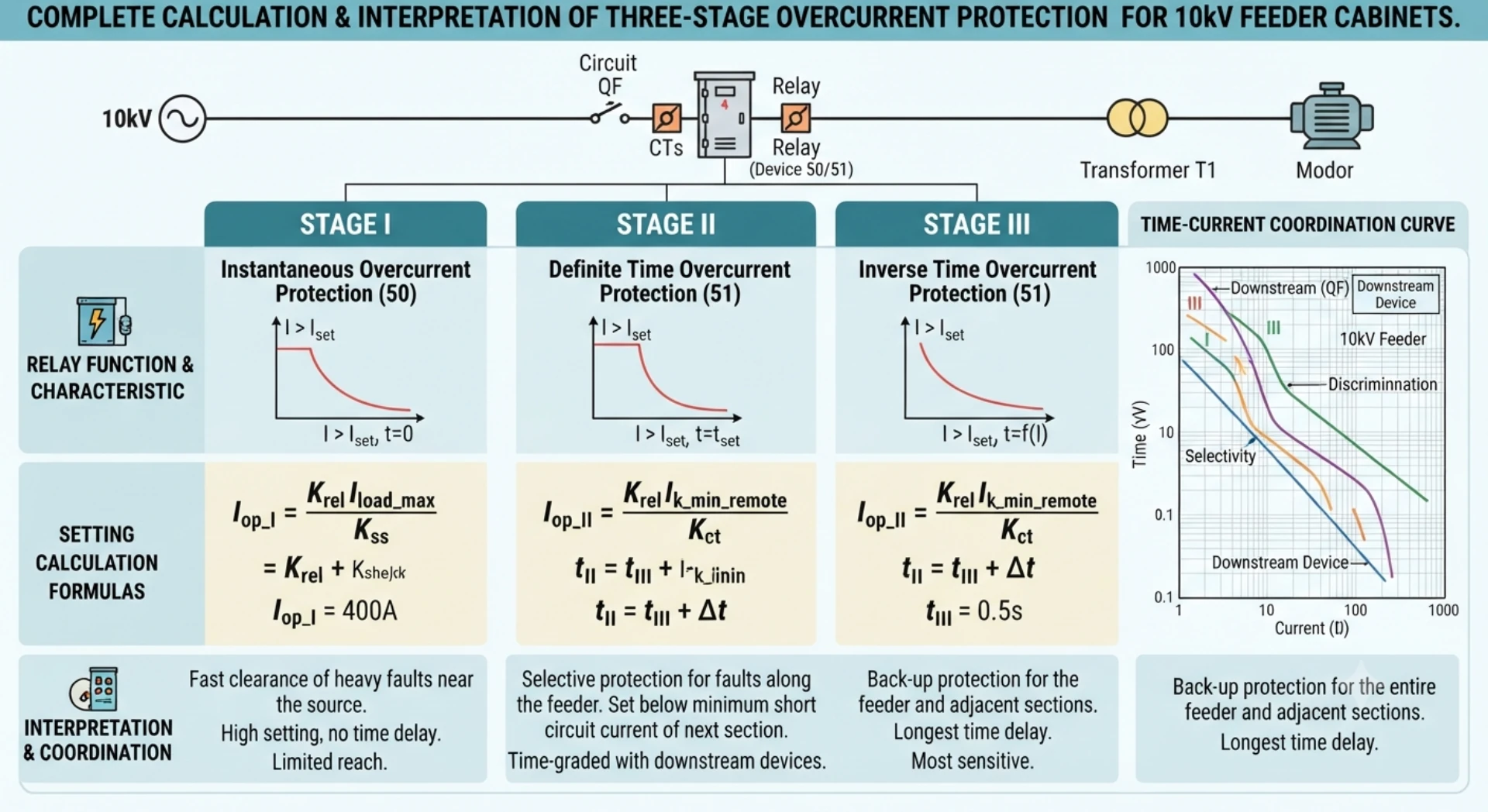
Complete Calculation & Interpretation of Three-Stage Overcurrent Protection for 10kV Feeder Cabinets
Three-Stage Overcurrent Protection
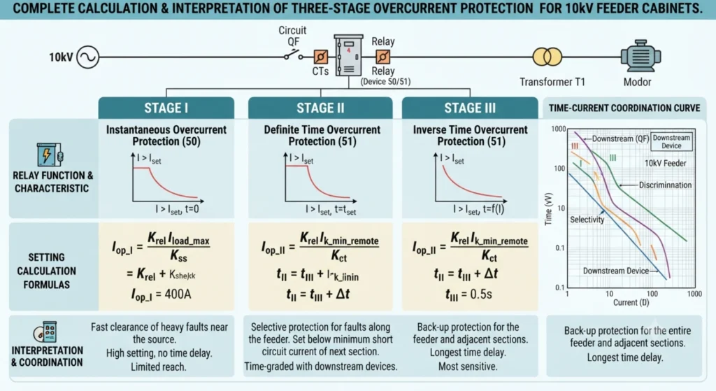
In factory power distribution rooms and workshop branch outgoing feeders, protection setting calculations often need to be completed on-site by engineers. This article systematically elaborates the full calculation method for three-stage overcurrent protection of 10kV outgoing feeder cabinets. Any errors or omissions are welcome to be pointed out in the comment section.
Definition & Division of Protection Settings
Protection setting values refer to the trip thresholds preset for relay protection devices, which specify the current magnitude to trigger tripping and the intentional delay duration.
Standard three-stage overcurrent protection is configured for 10kV outgoing feeders in factory power distribution rooms, detailed as below:
- Stage I: Instantaneous Overcurrent Protection Trips with zero intentional delay, only covering the initial section of the protected line.
- Stage II: Time-Delayed Instantaneous Overcurrent Protection Equipped with a short time delay, covering the entire length of the protected line.
- Stage III: Definite Time Overcurrent Protection Adopts a long fixed delay, serving as backup protection for the local line and all subordinate outgoing feeders.
Stage I vs Stage II vs Stage III
| Stage | Main Function | Time | Protection Range |
|---|---|---|---|
| Stage I | Instantaneous Overcurrent | Instantaneous | Near-end |
| Stage II | Time-Limited Instantaneous | Short Delay | Full feeder |
| Stage III | Definite-Time Overcurrent | Longer Delay | Backup |
Coordination Logic of Three Stages
Near-end faults are cleared instantaneously; full-line faults are eliminated via time-delayed instantaneous backup; hidden remote-end faults are isolated by delayed overcurrent protection. This scheme ensures rapid fault isolation while maintaining protection selectivity: only the faulty circuit trips without undesired cascaded tripping of healthy feeders.
Four Basic Parameters Required Before Calculation
All setting calculations rely on fundamental original parameters, which shall be documented formally in the setting calculation sheet.
General 50/51 relay setting principles are explained in our Overcurrent Protection Relay Setting Guide
System Rated Parameters
Rated system voltage Ue = 10.5kV (10.5kV is uniformly adopted for short-circuit calculation instead of 10kV)
System short-circuit apparent power S′′: provided by the local power supply bureau, unit: MVA
System impedance formula:
Xs=S′′Ue2
Example: If system short-circuit capacity = 500MVA
Xs=50010.52=0.2205 Ω
Line Parameters
Line length L (km);
Unit reactance X1: 0.08Ω/km for 10kV cables, 0.4Ω/km for overhead lines
Total line impedance:
Xl=X1×L
Maximum Line Load Current Imax
The overcurrent setting must avoid the maximum steady-state load current to prevent incorrect tripping during normal full-load operation.
Two acquisition methods: extract historical peak operating current, or calculate three-phase rated current based on transformer capacity:
Imax=3×UeS
Reliability Coefficient & Return Coefficient
- Reliability coefficient for instantaneous protection Krel: 1.2~1.3 for microcomputer-based protection
- Reliability coefficient for overcurrent protection Krel.oc: 1.25~1.35 for workshop feeders with heavy motor loads
- CT return coefficient Kre: unified as 0.9~0.95 for microcomputer protection
Practical Setting Calculation Case
Given Conditions (Actual parameters of 10kV cable outgoing feeder in factory):
Rated system voltage Ue=10.5kV; system short-circuit capacity S′′=300MVA
Cable model: YJV22-8.7/10kV, cross-section 95mm², length 2km, unit reactance X1=0.12Ω/km
Maximum line load current Imax=180A; CT ratio = 200/5
Stage I: Setting of Instantaneous Overcurrent Protection
Setting Principle: Escape the maximum three-phase short-circuit current at the line far end to guarantee selectivity; the protection shall not act for faults outside the line outlet.
Primary operating current formula:

Ik.max: maximum three-phase short-circuit current at the line terminal
Step 1: Calculate system impedance

Step 2: Calculate total line impedance
Xl=0.12×2=0.24 Ω
Total equivalent impedance:
XΣ=Xs+Xl=0.3675+0.24=0.6075 Ω
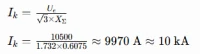
Step 3: Compute primary three-phase short-circuit current at line terminal
Step 4: Determine primary Stage I setting, take Krel=1.3
Iop.I=1.3×10000=13000 A
Operating time: Zero intentional delay for Stage I instantaneous protection, with inherent tripping delay within dozens of milliseconds.
Sensitivity requirement: The protection coverage shall account for no less than 15%~20% of total line length, which is satisfied in this case.
Stage II: Setting of Time-Delayed Instantaneous Overcurrent Protection
Setting Principle: Escape the Stage I instantaneous setting value of the subordinate feeder while covering the entire local line. The time delay shall be one standard time grading margin (typically 0.5s) longer than that of the downstream feeder.
Primary operating current formula:
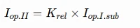
Assume the subordinate feeder Stage I primary setting = 10000A, Krel=1.15
Iop.II=1.15×10000=11500 A
Time delay setting: 0.5s longer than downstream instantaneous protection. If downstream Stage I trips at 0s, local Stage II is set to 0.5s.
Sensitivity verification: When short-circuit occurs at line terminal, the sensitivity factor shall be ≥1.25; extend delay or reduce setting value if the requirement fails.
Stage III: Definite Time Overcurrent Protection (Most widely used backup protection for plant outgoing feeders)
Setting Principle: Escape the maximum long-term load current, and serve as backup protection for the local line and all subordinate outgoing circuits.
Primary operating current formula:
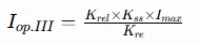
Parameter selection: Krel=1.2, motor self-start coefficient Kss=1.5, Kre=0.9, Imax=180A
Substitute values for calculation:
Iop.III=0.91.2×1.5×180=360 A
Time delay principle: Adopt stepped coordination with 0.5s incremental grading level by level. Outgoing feeder overcurrent protection is commonly set to 1.5s or 2.0s to coordinate hierarchically with downstream switchgears.
Two types of sensitivity verification:
- Local backup (short-circuit at local line terminal): Sensitivity factor ≥1.3
- Remote backup (short-circuit at subordinate line terminal): Sensitivity factor ≥1.2 Prolong time delay stage by stage if sensitivity criteria cannot be met.
Secondary Value Conversion for CT & Setting Entry Formula for Protection Devices
Microcomputer protection devices adopt secondary current values for parameter entry, which need conversion based on CT transformation ratio.
CT ratio n=200/5=40
Secondary setting conversion formula:
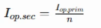
Take Stage III overcurrent primary setting 360A as an example:
Iop.III.sec=40360=9 A
All instantaneous and time-delayed instantaneous secondary settings shall be converted via this formula before being programmed into the relay protection unit of high-voltage switch cabinets.
Five Common Calculation Misunderstandings
Misunderstanding 1: Adopt 10kV instead of 10.5kV for short-circuit current calculation
System nominal voltage 10.5kV must be applied for all short-circuit calculations, while 10kV is only used for load current computation. Incorrect voltage selection causes huge deviation in short-circuit current and complete failure of instantaneous protection settings.
Misunderstanding 2: Neglect the motor self-start coefficient Kss
Workshops equipped with large quantities of water pumps, fans and motors will generate 5~7 times rated starting current when power is restored after outage. Omitting the self-start coefficient leads to undersized overcurrent settings and frequent incorrect tripping during power re-energization. Kss shall be above 1.5 for motor-intensive workshops.
Misunderstanding 3: Only calculate operating current without sensitivity check
Insufficient sensitivity means minor remote-end short-circuit faults cannot reach the setting threshold, resulting in protection failure to trip, persistent faults and ultimately cable burnout accidents.
Misunderstanding 4: Uniform time delay for all outgoing feeders without stepped coordination
Absence of 0.5s grading margin between upstream and downstream overcurrent time settings will cause the main upstream switch to trip preferentially upon downstream faults, triggering cascaded plant-wide power outages.
Misunderstanding 5: Mistakes in CT ratio conversion
Even with correct primary current calculation, reversed CT ratio during secondary value conversion leads to excessively high or low actual tripping thresholds, causing either protection refusal to operate or unwanted tripping. Double verification is mandatory after setting entry.
Summary
For 10kV power distribution room outgoing feeders:
- Stage I Instantaneous Protection: Set to escape maximum terminal short-circuit current, zero delay, only protects the front section of the line.
- Stage II Time-Delayed Instantaneous Protection: Set to evade downstream Stage I setting, with 0.5s delay, covering the entire line length.
- Stage III Definite Time Overcurrent Protection: Configured to avoid maximum load and motor inrush current, long fixed delay, acting as full-range backup protection.
Factory power distribution systems contain numerous lines and transformers with differentiated load characteristics and line lengths for each outgoing circuit. Independent setting calculation is required for every feeder; universal parameter templates shall not be applied indiscriminately, and targeted configuration of Three-Stage Overcurrent Protection must be implemented according to actual operating conditions.
As a leading supplier of overcurrent protection relays, we offer reliable overcurrent protection relay in China and bulk overcurrent protection relay wholesale in China. Our digital relays support three-stage overcurrent protection and flexible parameter configuration, perfectly fitting factory distribution, substation and new energy power systems.
FAQ
1. What is three-stage overcurrent protection?
A coordinated protection scheme with three levels — Instantaneous (Stage I) , Definite-Time (Stage II) , and Inverse-Time (Stage III) — each with different current and time settings to achieve fast clearing, full-line coverage, and selective coordination.
2. What are the three stages?
| Stage | Name | ANSI | Time Delay | Purpose |
|---|---|---|---|---|
| I | Instantaneous | 50 | No delay | Clears close-in severe faults (80–85% of line) |
| II | Definite-Time | 51 | Short delay | Protects full line length |
| III | Inverse-Time | 51 | Long delay (IDMT) | Backup protection and overloads |
3. Why does Stage I not protect the entire feeder?
To ensure selectivity with downstream protection. If Stage I covered the full line, it would trip for faults on downstream feeders — causing unnecessary outages. It is intentionally set to cover only the first 80–85% of the line from the source.
4. How is Stage II calculated?
Pickup current: Set lower than Stage I but above maximum load current.
Time delay: Set based on downstream protection time + coordination margin (typically 0.3–0.5 s).
Example: Downstream clears in 0.2 s → Stage II delay = 0.2 + 0.3 = 0.5 s
5. What is the purpose of Stage III?
- Backup protection — if Stage I/II fail
- Overload protection — sustained overloads
- Remote backup — if downstream protection fails
- Coordination — IDMT characteristic ensures longer delay for smaller currents
Stage III is the last line of defense.
6: What is three-stage overcurrent protection for 10kV feeders, and what are its three components?
A1: It is the core main protection configuration for 10kV distribution feeder cabinets, composed of Current Instantaneous Trip (Stage I), Time-limited Current Instantaneous Trip (Stage II), and Definite-time Overcurrent Protection (Stage III). The three stages cooperate in protection range and action time to realize full-range fault coverage of the feeder line.
7: What is the respective protection function of each stage?
A2:
Stage I (Instantaneous Trip): Acts instantly for near-end short-circuit faults with large current, pursuing fast tripping to isolate severe faults quickly.
Stage II (Time-limited Instantaneous Trip): Covers blind areas of Stage I protection, responsible for middle and front line faults, with a short time limit to ensure selective action.
Stage III (Definite-time Overcurrent): Serves as the backup protection for the whole line and adjacent lines, responsible for long-distance small-current faults and overload faults, with a longer fixed time limit.
8: What core parameters need to be calculated for three-stage overcurrent protection?
A3: The key calculation parameters include: maximum short-circuit current of the feeder, operating current setting value of each protection stage, action time limit, and sensitivity coefficient. All parameters must comply with the selectivity, rapidity, sensitivity and reliability requirements of power distribution protection.
9: Why is Stage I protection unable to cover the full feeder line?
A4: The setting current of Stage I protection is calculated according to the maximum short-circuit current at the end of the feeder. To avoid malfunction caused by short-circuit faults of the next-stage line, its setting value is relatively large, resulting in a protection blind area at the far end of the feeder, which cannot protect the full line.
10: What are the key criteria for judging qualified protection setting calculation?
A5: Three core criteria: First, sensitivity coefficient meets the standard (greater than the specified threshold); second, time limit coordination is reasonable to avoid cross-tripping; third, no malfunction or refusal action under normal operation and fault conditions.
11: What is the difference and connection between calculation and interpretation (setting) in the topic?
A6: Calculation refers to the quantitative solution of protection current and time parameters based on feeder operation data and short-circuit current formulas; interpretation (setting) refers to verifying, analyzing and calibrating the calculated data in combination with actual engineering conditions, and finally forming executable protection setting values for feeder cabinet devices.
12: What common problems exist in the field setting of 10kV feeder three-stage overcurrent protection?
A7: Common on-site problems include: unreasonable time limit coordination leading to over-tripping, insufficient sensitivity of Stage III protection for far-end faults, inaccurate short-circuit current calculation causing protection malfunction, and inconsistent setting parameters with actual load conditions.
13: What is the engineering significance of studying three-stage overcurrent protection calculation for 10kV feeder cabinets?
A8: Three-stage overcurrent protection is the most widely used and basic protection for 10kV distribution feeders. Accurate calculation and reasonable setting can effectively isolate line short-circuit and overload faults, reduce power failure range, ensure safe and stable operation of distribution network, and provide reliable technical support for on-site power distribution operation and maintenance.



About Author

Hello, I'm Leno Zhang. I have 15 years of experience in the power relay protection industry with extensive pre-sales and after-sales project experience. Our company specializes in various complete sets of relay protection and automation equipment. I can assist customers in solving all practical on-site project challenges and provide optimal integrated solutions.
Tell Us Your Requirement
High Quality
Stable performance, reliable design, ensuring safe operation for power system protection and grid stability.
Fast Delivery
Timely delivery to support your urgent orders and project schedules efficiently and professionally at any time.
Best Warranty
Professional Warranty: Reliable after-sales support for stable relay protection and long-term customer satisfaction.