

-
Leon Zhang sales consultant
-
Email: zxl635973785@gmail.com
-
Phone/WhatsApp: +86 13655813266
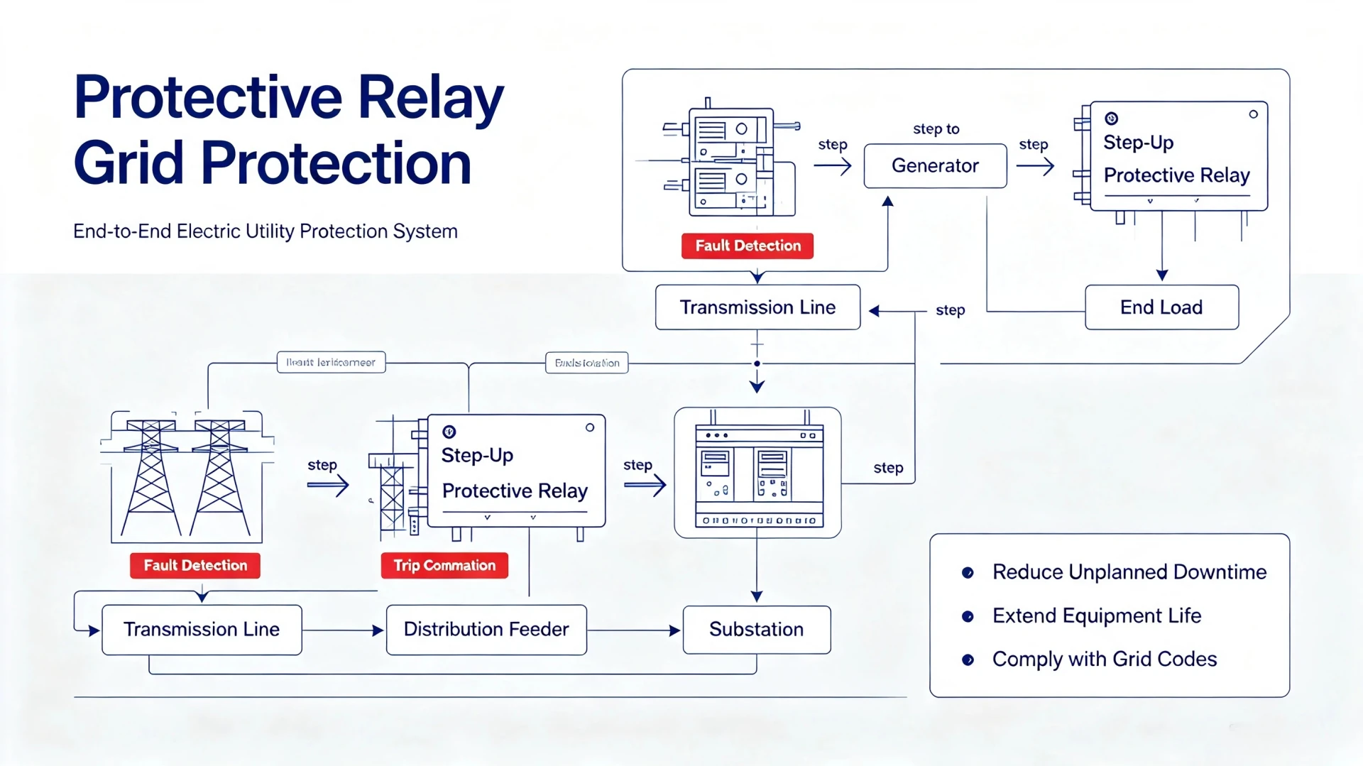
Protective Relay in Electric Utilities Market: Core Protection Schemes, ANSI Codes and Practical Deployment Considerations
The Role of Protective Relays in the Electric Utilities Market
For electric utilities, grid stability and operational reliability fully rely on solutions within the Protective Relay in Electric Utilities Market. Faults including short circuits, ground faults, overvoltage and reverse power flow may cause permanent damage to generators, transformers and transmission equipment, and even trigger large‑scale blackouts and cascading grid failures. Protective relays instantly isolate faulty sections to keep sound grid segments in operation, thus mitigating such risks.
Core Value for Utility Operators & EPC Contractors: Standardized, high-performance protective relays reduce unplanned downtime, extend equipment service life, minimize maintenance costs, and ensure full compliance with international grid operation codes.
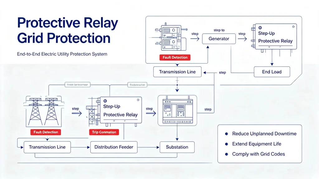
Core Applications of Protective Relays in Electric Utilities
Within the Protective Relay in Electric Utilities Market, electrical protective relays cover all key assets across the full power grid lifecycle. Each grid segment and equipment type requires customized protection logic to match operational characteristics and fault risks.
Power Generation Plant Protection
Within protective relaying for power generation systems, generation‑side protection focuses on preventing generator and unit transformer damage from internal and external grid abnormalities.
Key applications include generator differential protection, reverse power protection (to avoid generator motoring), loss of excitation protection, overcurrent/64 ground protective relay, and generator‑transformer unit integrated protection.
These relays isolate internal faults instantly to prevent unit burnout and grid back‑feeding failures.
Transmission Network Protection
Transmission lines operate at high voltage levels and undertake long-distance power transmission, requiring fast and accurate fault response. Core protection types include distance protection, line differential protection, directional overcurrent protection, line-to-ground fault protection, and auto-reclosing functions. Multi-zone protection design ensures graded response to near-end and far-end faults, guaranteeing transient stability of high-voltage grids.
Protective Relays in Substation
Substations are the hub of power grid energy conversion and distribution, with complex equipment and high fault impact. Relay protection covers power transformers, busbars, incoming/outgoing feeders, and circuit breakers. Key functions include transformer differential protection, busbar differential protection, breaker failure protection, and over/undervoltage protection, ensuring rapid isolation of substation internal faults.
Distribution Network Protection
Distribution networks face complex load conditions and frequent external faults. Relays provide feeder overcurrent, earth fault, directional protection, and recloser coordination protection. Combined with distribution automation technology, they realize fast fault location, isolation, and power restoration, minimizing power outage scope for end users.
Main Types of Utility-Grade Protective Relays (ANSI Standard)
Electric utilities adopt unified ANSI device function numbers for relay classification, ensuring consistent technical standards for global EPC projects, equipment procurement, and grid operation. The following are the most widely used relay types in utility scenarios.
Overcurrent Relays (ANSI 50/51)
The most basic and widely applied protection type for distribution feeders and low/medium-voltage equipment. ANSI 50 refers to instantaneous overcurrent protection for fast clearing of severe short-circuit faults; ANSI 51 is time-delayed overcurrent protection for coordinated protection of minor and persistent overcurrent faults.
Earth Fault Relays (ANSI 50N/51N)
Specially designed for ground fault detection in ungrounded or resistance-grounded power systems. It identifies leakage current and single-phase ground faults that ordinary overcurrent relays cannot detect, effectively preventing equipment insulation damage and personal electric shock risks in distribution networks.
Differential Protective Relays (ANSI 87 Series)
The highest-precision primary protection for core grid equipment, judging faults by comparing current differences at both ends of protected equipment. Common types include 87G (generator differential), 87T (transformer differential), 87B (busbar differential), and 87L (transmission line differential). It features high selectivity and zero misjudgment for internal faults.
Distance Relays (ANSI 21)
Specialized for high-voltage transmission line protection, calculating fault distance by measuring line impedance. It adopts three-zone protection logic: Zone 1 for instantaneous near-end fault clearing, Zone 2 for backup protection of near-end dead zones, and Zone 3 for remote line backup protection, balancing protection speed and coverage.
Directional Overcurrent Relays (ANSI 67/67N)
Applied to ring networks, parallel lines, and interconnected grids with bidirectional power flow. It judges fault current direction to avoid invalid tripping of healthy branches, solving protection coordination failures caused by bidirectional power flow in complex grid structures.
Voltage & Frequency Relays (ANSI 27/59/81)
ANSI 27 (undervoltage) and 59 (overvoltage) protect equipment from grid voltage anomalies; ANSI 81O/81U (over/under frequency) monitors grid frequency stability. They are core protection devices for grid off-grid, renewable energy grid-connection, and load shedding control.
Reverse Power Relays (ANSI 32)
Mainly used for generator protection to detect reverse power flow from the grid to the generator (generator motoring state). It trips in time to prevent generator rotor burnout and unit damage, which is mandatory for all grid-connected power plants.
Protection Function Matching for Typical Utility Assets
Different grid assets have distinct fault characteristics and operational risks, requiring matched ANSI protection function combinations under the classification of protective relays. The table below provides standardized protection configurations for EPC design, equipment procurement, and daily operation.
| Utility Asset | Core ANSI Protection Functions | Primary Protection Purpose |
|---|---|---|
| Generator | 87G, 32, 40, 46, 50/51, 59, 81 | Prevent internal short circuit, reverse power, loss of excitation, and frequency/voltage anomaly damage |
| Power Transformer | 87T, 50/51, 50N/51N, 49, 63 | Isolate internal winding faults, overheating, and oil pressure abnormalities |
| Transmission Line | 21, 87L, 50/51, 67 | Fast clearing line short-circuit and ground faults, adapt to bidirectional power flow |
| Distribution Feeder | 50/51, 50N/51N, 67 | Rapidly isolate distribution network faults, reduce outage range |
| Busbar | 87B | Precise protection for substation busbar key node faults |
| Capacitor Bank | 50/51, 59, Unbalance Protection | Prevent overvoltage, overcurrent, and phase unbalance damage |
| Auxiliary Motor | 49, 50/51, 46, 48/51LR | Protect against motor overload, stalling, and negative sequence faults |
| Circuit Breaker | 50BF, Trip Circuit Monitoring | Prevent breaker failure and trip circuit failure |
Key Note: All utility protection schemes adopt a primary + backup protection mechanism. Primary protection realizes instantaneous fault clearing, while backup protection acts with delay to cover primary protection failure risks, ensuring 100% fault isolation coverage.
Protection Coordination & Relay Setting Guidelines
Protection coordination is the core of utility grid protection design, ensuring orderly and hierarchical action of all relays in the grid to avoid protection disorder.
Primary vs. Backup Protection Coordination
Primary protection acts first with zero delay for rapid fault clearing; backup protection is configured with a reasonable time multiplier delay to take over fault isolation when primary protection or circuit breaker fails, forming a double safety barrier.
Time-Current Coordination Rules
Relay setting must match system load current, short-circuit current level, CT/PT ratio, transformer impedance, and system grounding mode. Reasonable pickup current and time delay settings ensure upper and lower level relay coordination without crossing action.
Risks of Incorrect Settings
Unreasonable relay parameters directly lead to frequent nuisance tripping, failure to clear permanent faults, equipment overheating damage, large-scale power outages, and even cascading grid failures, causing huge economic losses to utilities.
Global Industry Standards for Utility Protective Relays
All utility protective relays used in international EPC and grid projects must comply with unified IEC and IEEE standards to ensure cross-project compatibility and operational standardization.
- IEC 60255: Core standard for measuring relays and protection equipment, defining basic performance, testing methods, and EMC requirements for relays; the latest EN IEC 60255-26:2025 further optimizes electromagnetic anti-interference indicators for smart relays
- IEC 61850: Unified communication standard for digital substations, regulating substation device modeling, GOOSE messaging, and process bus communication
- IEEE C37 Series: American standard for power system protection, specifying relay protection logic and coordination rules for transmission and distribution networks
- ANSI Device Numbering Standard: Unified global protection function coding standard for consistent project design and equipment operation
- Grid Code Specifications: Regional utility grid operation rules, supplementing customized protection requirements for local power grids
Digital Transformation & Market Trends
The global electric utility industry is accelerating the replacement of legacy equipment and digital upgrading, driving the iterative upgrading of protective relay technology.
Legacy Relay Upgrading
A large number of aging electromechanical and static relays in old substations have problems such as single function and poor stability. Utilities are accelerating their replacement with multi-functional numerical relays to improve grid safety margins.
Digital Substation Popularization
IEC 61850-based digital protection systems and digital CT/VT devices cancel traditional hard-wiring, realizing full digitalization of protection links, improving system reliability and construction efficiency.
Renewable Energy Grid Adaptation
Large-scale access of photovoltaic, wind power, and energy storage systems leads to bidirectional power flow and fluctuating short-circuit current in the grid. New adaptive relays and wide-area protection technologies have become mainstream demands.
Intelligent Operation & Maintenance
Modern relays support remote fault recording, event query, and condition-based maintenance, reducing on-site inspection frequency and operation and maintenance costs for utilities.
Cybersecurity Enhancement
Digital relays with network communication functions face increasing cybersecurity risks. New generation utility relays integrate encryption authentication and access control functions to meet grid cybersecurity requirements.
Relay Protection for Renewable Energy Utilities
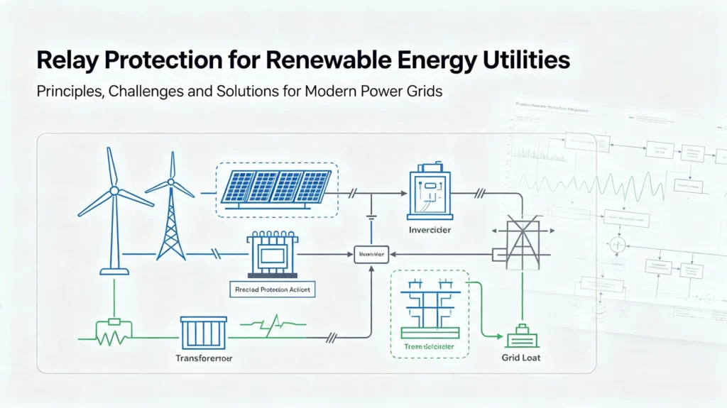
New energy power stations have unique grid-connection characteristics, requiring specialized relay protection schemes different from traditional thermal power plants.
Solar PV Power Plants
Core protection functions include inverter over/undervoltage protection, over/under frequency protection, anti-islanding protection, and reverse power protection, solving grid disconnection and power back-feeding risks caused by PV output fluctuation.
Wind Power Plants
Focus on generator transformer protection, grid-connection fault protection, and fault ride-through (FRT) function to ensure wind turbines can continuously operate during grid transient faults and meet grid code requirements.
Battery Energy Storage Systems (BESS)
Cover AC/DC bidirectional protection, PCS overcurrent/short-circuit protection, and battery cluster unbalance protection, adapting to frequent charge-discharge switching operating conditions of energy storage systems.
Testing & Maintenance Standards for Utility Relays
Regular testing and standardized maintenance are essential to ensure long-term stable operation of protective relays, which is a mandatory daily work for utility operation and maintenance teams.
Core Testing Items
Including secondary injection testing, primary injection testing, trip circuit testing, communication function testing, setting verification, and fault record analysis. Secondary injection testing is the most conventional detection method to verify relay action accuracy.
Standard Maintenance Cycle
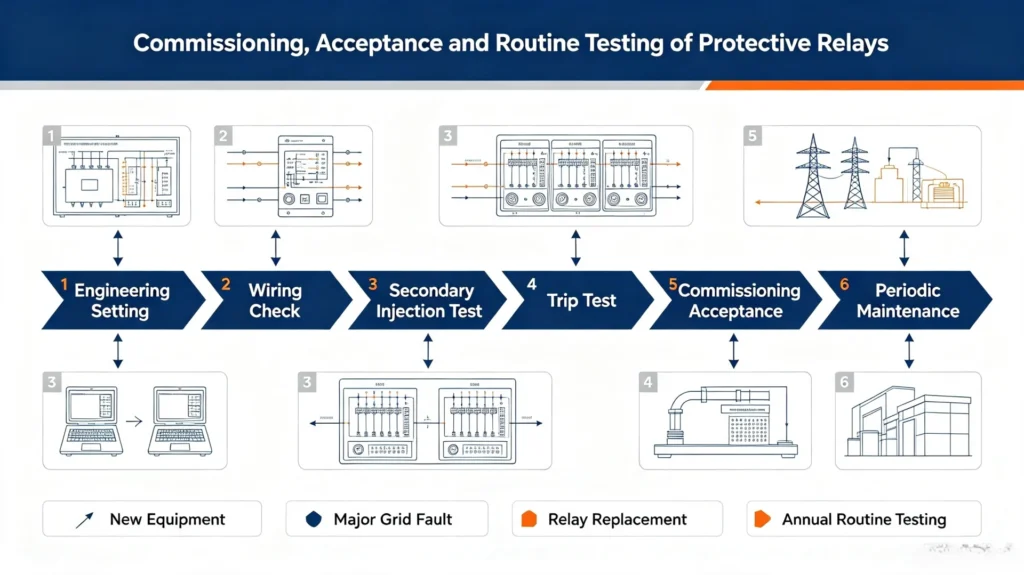
Commissioning full testing for new equipment, acceptance testing of protective relays, special inspection and testing after major grid faults, parameter verification and functional testing after relay replacement or setting modification; annual periodic routine testing for in‑operation equipment.
Utility Relay Selection Criteria (EPC & Buyer Guide)
Professional selection of protective relays needs to balance technical adaptability and long-term commercial value, suitable for EPC project procurement and owner equipment bidding standards.
Technical Selection Factors
- Match system voltage level, rated current, and short-circuit current parameters
- Complete required ANSI protection functions and protection zone quantity
- Compatible with on-site CT/PT ratio and secondary loop parameters
- Support standard communication protocols (IEC 61850/Modbus/DNP3)
- Complete fault recording and event storage functions
- Meet IEC 60255 EMC and environmental resistance standards
Commercial Selection Factors
- Low total cost of ownership (TCO), including purchase, maintenance, and replacement costs
- Stable product supply and short delivery lead time
- Complete after-sales service, local technical support and spare parts guarantee
- Long-term product iteration and compatibility assurance
- Formal warranty and professional commissioning guidance service
Current Industry Deployment Challenges
Global electric utility protection relay deployment faces multiple practical challenges in grid upgrading and new energy integration:
- Aging legacy protection infrastructure with mixed old and new equipment, difficult for unified coordination
- Increased grid complexity caused by large-scale new energy access and bidirectional power flow
- Fluctuating short-circuit current levels, increasing protection setting and coordination difficulty
- Cybersecurity risks of digital relay network communication
- Global shortage of professional grid protection engineers, insufficient on-site technical support capacity
Practical Utility Substation Application Case
Project Overview: 110/33 kV urban utility substation, equipped with 110kV incoming transmission line, main power transformer, 33kV busbar, and multiple outgoing distribution feeders, serving urban industrial and residential loads.
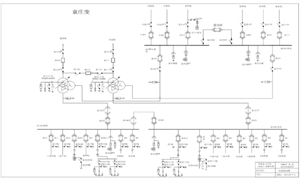
Standard Protection Scheme:
- 110kV transmission line: ANSI 21 distance protection + ANSI 67 directional backup protection
- Main transformer: ANSI 87T differential primary protection + overcurrent/earth fault backup protection
- 33kV busbar: ANSI 87B busbar differential protection
- Distribution feeders: ANSI 50/51 + 50N/51N overcurrent and earth fault protection
- Global configuration: breaker failure protection and system backup protection
Commissioning & Testing: Completed CT/PT polarity verification, secondary injection function test, breaker trip linkage test, and SCADA communication debugging, fully compliant with IEC and local grid code standards.
Buyer Checklist for Protective Relay Procurement
For EPC contractors and utility owners, use this checklist to complete standardized procurement and inspection:
- [ ] Matched ANSI protection function configuration
- [ ] Compliance with system voltage, current and short-circuit level parameters
- [ ] Compatible with on-site CT/PT ratios
- [ ] Qualified protection coordination logic and parameter settings
- [ ] Full IEC 60255 & IEC 61850 standard compliance
- [ ] Complete communication protocol and IEC 61850 compatibility
- [ ] Sufficient digital input/output ports
- [ ] Complete fault recording and data storage function
- [ ] Qualified environmental and EMC resistance rating
- [ ] Professional commissioning and testing technical support
- [ ] Complete warranty, after-sales service and spare parts guarantee
FAQ
1.What is a protective relay in electric utilities?
It is a core grid safety device that monitors power system operating parameters, identifies faults, and controls circuit breakers to isolate faulty equipment, ensuring grid operational stability and equipment safety.
2.What is the difference between a protective relay and a circuit breaker?
Relays are judgment and command devices responsible for fault detection and trip signal output; circuit breakers are execution devices responsible for physical circuit breaking and isolation. The two work together to complete grid protection.
3.Why are numerical relays replacing electromechanical relays?
Numerical relays integrate multiple functions, support remote configuration and fault recording, have higher protection accuracy and stability, and adapt to digital substation and smart grid construction requirements, with lower long-term operation and maintenance costs.
4.What standards must utility protection relays comply with?
Core compliance standards include IEC 60255 (basic performance & EMC), IEC 61850 (digital communication), IEEE C37 series (protection logic), and ANSI function number specifications.
5.How often should utility relays be tested?
Annual routine testing is required for in-operation equipment; full testing is mandatory after equipment commissioning, parameter modification, fault occurrence, and equipment replacement.
6.How protective relays work?
Protective relays continuously monitor current, voltage, and other electrical quantities from the power system.
- Sensing & Measurement: They collect real‑time electrical signals via current transformers (CT) and voltage transformers (VT).
- Fault Judgement: Compare measured values against preset threshold settings (ANSI protection functions). When abnormal conditions (overcurrent, short‑circuit, reverse power, loss‑of‑excitation etc.) are detected, the relay identifies a fault.
- Trip Output: If fault criteria are satisfied, the relay sends a trip command to the circuit breaker.
- Fault Isolation: The breaker opens quickly to disconnect the faulty equipment or line. This limits equipment damage and prevents fault spread across the grid.
7.What are the essential qualities of protective relays?
The four essential qualities of protective relays are selectivity, speed, sensitivity, and reliability. These core characteristics determine whether protection can operate correctly under power‑system fault conditions.
Conclusion
As protective relays are the fundamental guarantee for safe and stable operation of electric utility power grids, the protective relay market size is expanding alongside the development of digital substations and new‑energy power systems, with relay protection technology evolving toward intelligence, digitization, and integration.
For utility operators and EPC contractors, standardized relay type selection, accurate protection coordination, strict testing and maintenance are key measures to reduce grid failure rates and improve power supply reliability. Modern numerical protective relays with IEC 61850 compatibility, complete protection functions, and reliable environmental adaptability have become the preferred solution for new construction and renovation projects of global power utilities.
Reference & Technical Sources
- IEC 60255 Series: Measuring Relays and Protection Equipment (2013/2025 Latest Version)
- IEC 61850 Series: Communication Networks and Systems for Power Utility Automation
- IEEE C37.100: IEEE Standard for Power System Protection Relays
- ANSI/IEEE Standard Device Numbers for Power System Protection Functions
- EN IEC 60255-26:2025 Electromagnetic Compatibility Requirements for Protection Devices
- International Energy Agency (IEA): Global Electricity Grid Modernization Report 2025
- IEC 63522-36:2025 Electrical Relays Testing Standard



About Author

Hello, I'm Leno Zhang. I have 15 years of experience in the power relay protection industry with extensive pre-sales and after-sales project experience. Our company specializes in various complete sets of relay protection and automation equipment. I can assist customers in solving all practical on-site project challenges and provide optimal integrated solutions.
Tell Us Your Requirement
High Quality
Stable performance, reliable design, ensuring safe operation for power system protection and grid stability.
Fast Delivery
Timely delivery to support your urgent orders and project schedules efficiently and professionally at any time.
Best Warranty
Professional Warranty: Reliable after-sales support for stable relay protection and long-term customer satisfaction.