
-
Leon Zhang Sales Manager
-
Email: sale@relayprotect.com
-
Phone/WhatsApp: +86 13655813266
Medium Voltage Switchgear: Bay, Class, and the Ratings That Size It
Medium voltage switchgear, bay structure, IEC 62271 class, AIS versus GIS, short circuit rating, and the commissioning sequence that proves the trip chain before energizing the bay.
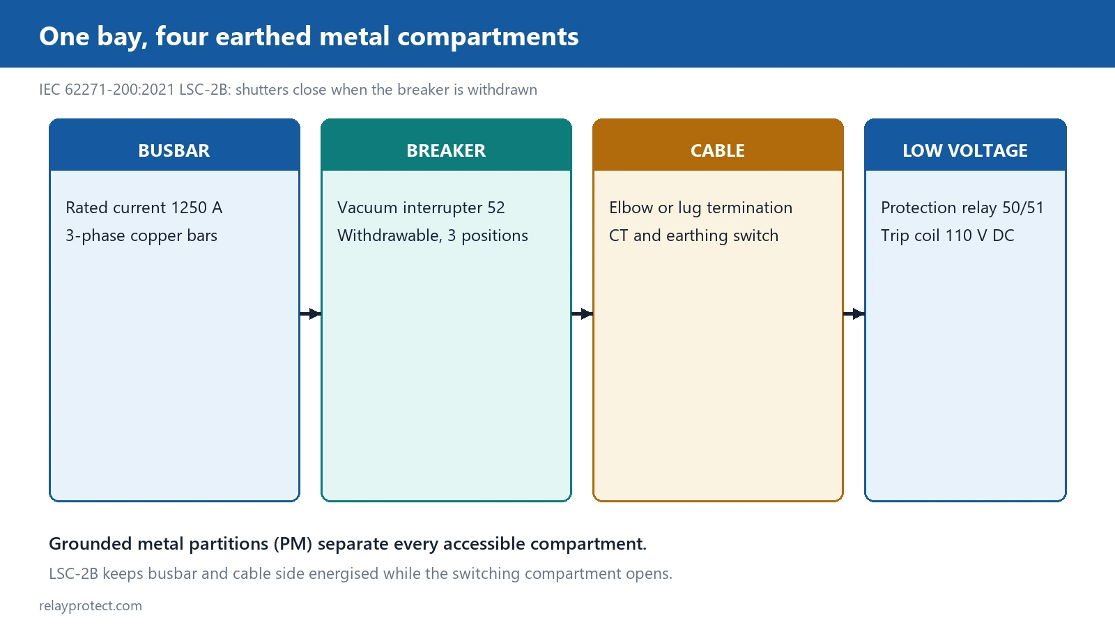
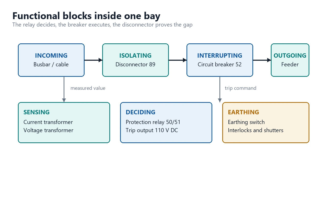
Medium voltage switchgear: a compact assembly of breakers, disconnectors, instrument transformers and control gear that distributes and protects a 1 kV to 52 kV system. The bay is the unit: a bus section, a breaker, a disconnector and the cable or busbar termination inside one enclosure, with the protection and control relay chained off its CT and VT secondary circuits. The IEC 62271 series sets the test regime; IEC 61850 is the communication layer that ties the bays together.
At a glance: what decides a medium voltage switchgear
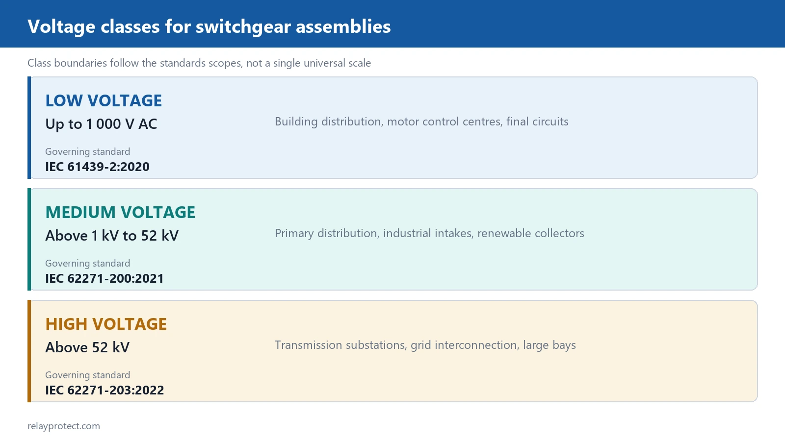
- Class: 1 kV to 52 kV; the common utility classes are 7.2, 12, 15, 24, 36 and 40.5 kV
- The two families: air-insulated (AIS) and gas-insulated (GIS); the insulation medium sets the footprint
- The bay: bus section, breaker, disconnector, earthing switch, CT/VT, cable termination, all in one compartmented enclosure
- Short circuit: the rated short circuit breaking current kA must carry the available fault current at the bus, with margin
- Protection: the bay CTs feed the digital multifunction protective relay that decides trip, and the breaker executes it
- Control: a switchgear controller or RTU closes the loop over IEC 61850
Where does medium voltage switchgear actually sit in the system?
Between the transformer and the 400 V bus. The medium voltage switchgear takes the utility or the substation feeder, sectionalizes it, and hands the power off to the distribution transformer, the capacitor bank, or the station service load. Each bay is one circuit: the incoming feeder, the outgoing line, or the transformer, with its breaker and its protection. That is why the number of bays is the first dimension: one per circuit you have to section and protect.
The three roles every bay plays
Every bay is doing three jobs at once. It carries the load, it gives the operator a way to isolate one circuit without dropping the bus, and it provides the sensing points, the CTs and VTs, that feed the protection. A bay without a good isolation point is where the outage planning starts to hurt, because you cannot service one feeder without tripping the whole bus.
What is the voltage class, and why does it fix the design?
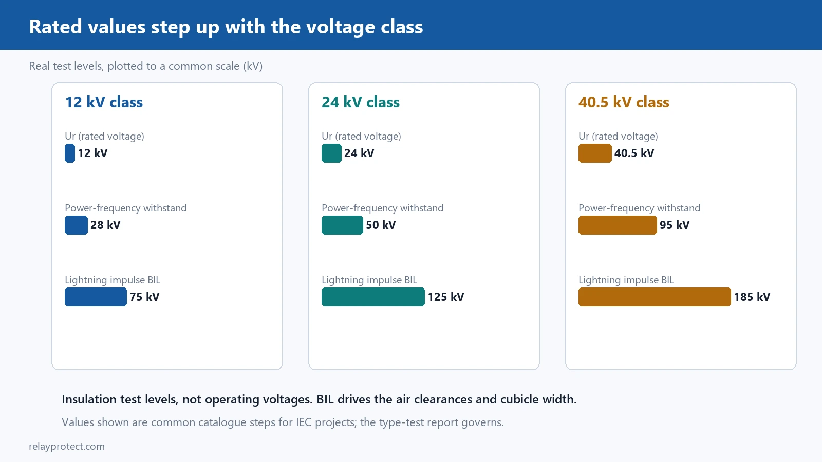
The class is the rated voltage the enclosure is built and tested for, and it drives the clearances, the insulation and the test levels. A 12 kV bay and a 40.5 kV bay are not the same box: the higher class needs the wider phase spacings, the higher power frequency withstand and the higher impulse levels, and all of that shows up in the footprint and the cost. The IEC 62271 series is the test regime that defines those levels, and the bay is only as good as its test certificate.
AIS or GIS: which insulation fits the site?
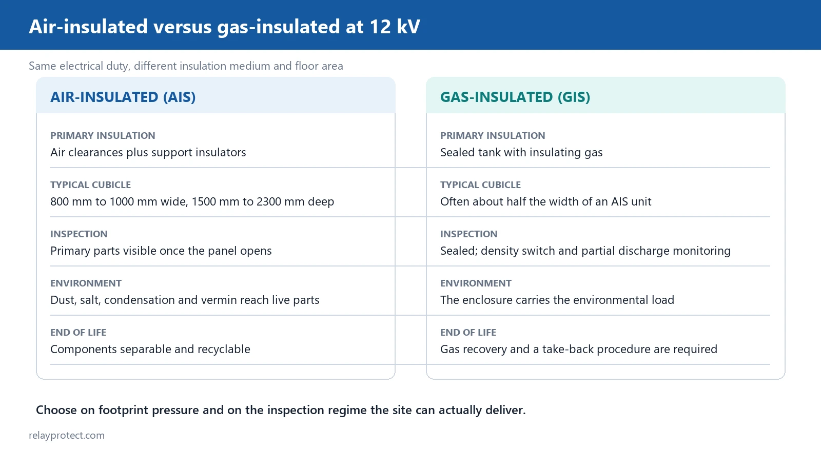
Air-insulated is the default where space is not the constraint: it is cheaper to buy, easier to open for service, and the operator can see the contacts and the mechanism. Gas-insulated compresses the same bay into a fraction of the footprint, and it is the answer where the site is a city corner or a retrofit into an existing building. The trade is that a GIS is sealed and the insulation is monitored, not opened, so the maintenance model is condition-based, not routine.
Footprint is the deciding number
Compare the two at the same kV and current and the footprint gap is the whole argument. A GIS is smaller and the enclosure is compact, but the cost and the sealed-gas maintenance are higher, and the SF6-free options are still maturing. Where the plot is open and the budget is the limit, AIS wins. Where the plot is a city block or a retrofit, GIS buys the space back.
What are the ratings that size the whole bay?
Three numbers on the nameplate decide the rest. The rated voltage, the class. The rated current, the continuous carry. And the rated short circuit breaking current, the fault let-through the breaker must clear at the bus. The last one is the one that gets checked against the system study, because if the breaker cannot clear the available fault current, the bay fails where it matters most. The margin is set by the standard, and you quote it as a kA rating, not a guess.
How does the protection and control chain off the bay?
The bay CTs and VTs are the sensing layer. They feed the protection relay, which is where the line protection relay or the multifunction relay sits, and it is the relay that decides whether the breaker trips. The control side is where the communication panel and the switchgear controller close the loop: the operator command, the interlock, and the status all flow through the control circuit, and the interlocks are what keep a breaker from closing on a closed earth.
Interlocks are the safety net
A medium voltage bay runs on interlocks: the breaker cannot close on a closed earthing switch, the disconnector cannot open while the breaker is closed, and the earthing switch only closes when the breaker is open and the bay is de-energized. Those mechanical and electrical interlocks are the layer that keeps a human from wiring the system into a short, and a controller that skips one of them is the bug that trips the whole bay on a routine operation.
How do you commission and check the bay before it goes live?
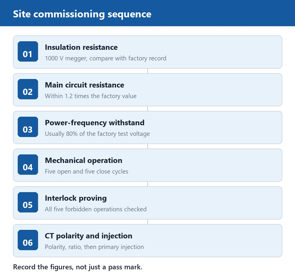
Commissioning is a sequence, not a single test. Insulation resistance on the primary, continuity on the secondary, the relay injection against the settings, the mechanism operation on the breaker, and the interlock proving. The protection relay testing stage is where the settings get verified against the system study, and the trip coil is checked against the breaker’s operating time. A bay that passes every test individually but fails the sequence still has a trip that will not clear in time.
What does a field failure on a bay actually look like?
Most bay comebacks are one of three. A breaker that will not close because the closing coil or the control circuit is open, a relay that trips on a false signal because the CT secondary is open and the magnetizing current is being misread, and a bay that trips on a fault it should have carried because the protection setting is one step too sensitive. The common thread is that the bay hardware is fine and the failure is in the chain around it: the control, the CT, or the setting.
Bottom line: picking the bay that holds up on the site
Start from the class and the current, and check the short circuit breaking kA against the system study before anything else. Pick AIS where the site is open and the budget leads, GIS where the footprint is the constraint. Then run the interlocks and the protection chain so the bay trips on its faults and not on its control. Get those four right and the medium voltage switchgear is a bay that carries the load, isolates a circuit, and clears its faults.
Field record
A 24 kV bay tripped on a feeder the protection said was healthy. The bay had been re-set after a CT was replaced and the CT secondary had been left open on one phase while the relay was still in service. The open CT threw a magnetizing signal the relay read as a fault, and the breaker cleared the whole feeder. The fix was to short the CT secondary before the relay was pulled and to verify the injection test after the CT was in, and the bay has not tripped on a healthy feeder since.
Technical Reference
| Item | Value / source | Note |
|---|---|---|
| Voltage class | 1 kV to 52 kV (IEC 62271) | 7.2, 12, 15, 24, 36, 40.5 kV common |
| Insulation families | AIS and GIS | Footprint is the deciding number |
| Short circuit rating | Rated breaking kA | Checked against the system study |
| Test regime | IEC 62271 series | Power frequency and impulse levels |
| Communication | IEC 61850 | Bay to controller and RTU |
Related Reading
- Line protection and control panel – the relay panel that the bay CTs and VTs feed.
- Smart switchgear controller – the controller that closes the bay control loop.
- Power SCADA monitoring cabinet – the monitoring layer the bays report into.
- Digital multifunction protective relay – the relay that decides the trip on the bay.
FAQ
What is medium voltage switchgear in one line?
It is the compact enclosure that carries, isolates and protects one medium voltage circuit, with the breaker in the middle and the sensing and the protection chained off it. The bay is the unit, and the IEC 62271 class is what sizes it.
Should I pick AIS or GIS for a new site?
Where the plot is open and the budget leads, pick AIS for its lower cost and easier service. Where the footprint is a city corner or a retrofit, GIS buys the space back at a higher price and a sealed-gas maintenance model. The class and the current are the same; the insulation medium is the deciding number.
How do I check the short circuit rating?
Run the system study to get the available fault current at the bus, and the rated short circuit breaking kA on the breaker must carry it with the standard margin. If the breaker is undersized, the bay fails where it matters most, and the rating is the number that has to be verified against the study, not the nameplate default.
Why does a medium voltage bay trip on a healthy feeder?
Most often the CT secondary is open or the relay is one step too sensitive, and the relay reads a fault that is not there. Check the CT continuity and re-run the injection test before you blame the breaker. A bay that trips on a healthy feeder is a sensing or a setting problem, not a breaker problem.
About Author

Hello, I'm Leon Zhang. I have 15 years of experience in the power relay protection industry with extensive pre-sales and after-sales project experience. Our company specializes in various complete sets of relay protection and automation equipment. I can assist customers in solving all practical on-site project challenges and provide optimal integrated solutions.
Tell Us Your Requirement



High Quality
Stable performance, reliable design, ensuring safe operation for power system protection and grid stability.
Fast Delivery
Timely delivery to support your urgent orders and project schedules efficiently and professionally at any time.
Best Warranty
Professional Warranty: Reliable after-sales support for stable relay protection and long-term customer satisfaction.