
-
Leon Zhang Sales Manager
-
Email: sale@relayprotect.com
-
Phone/WhatsApp: +86 13655813266
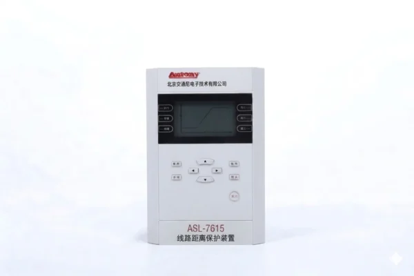
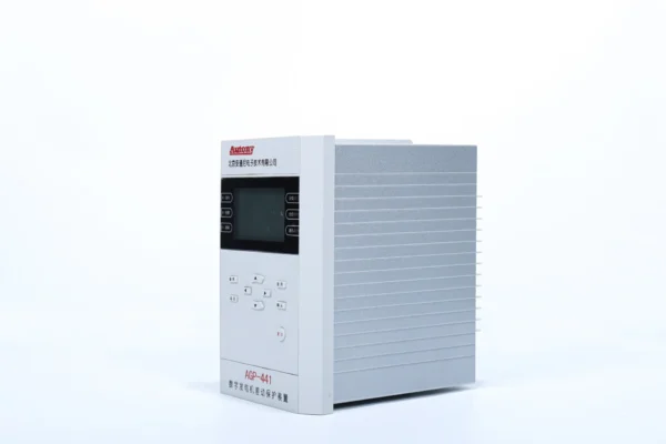
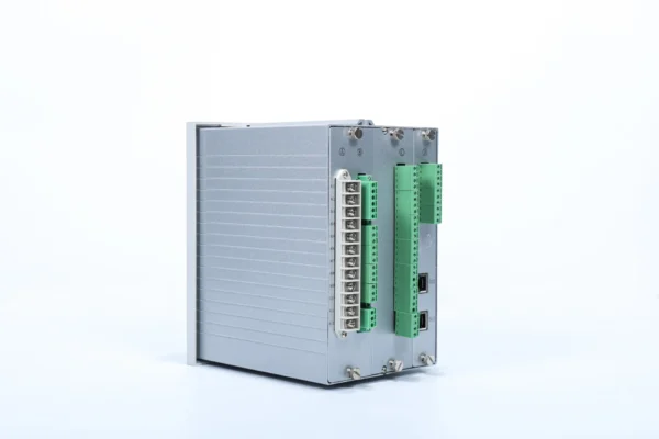
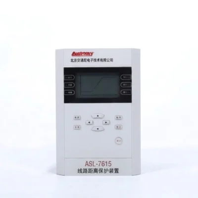
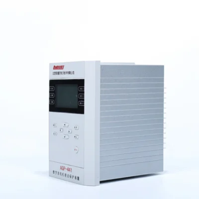
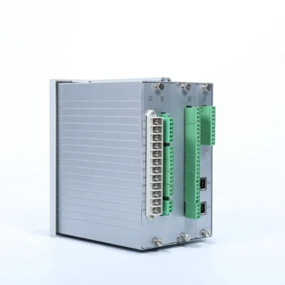
Line Distance Protection Relay | ANSI 21
ASL-7615 is a numerical line distance protection relay designed for transmission line protection, featuring ANSI 21 distance protection and integrated backup protection functions.
Function Configuration
21/51/51N/51G/79/27/49/81
Communication Mode:Optional: RS-485, CAN bus, Ethernet, IEC 60870-5-103 (IEC-103)
Send your requirements, we will quote for you within 12 hours
MOQ: 1 setLead time: 7-15 working daysPayment: T/T, L/C, Western Union, PayPalWarranty: 12 monthsTrade terms: EXW, FOB, CIF, DDUCertification: CEDifferent rating, protocol or mounting: send the specification and we confirm before you order.
Description
What is an ANSI 21 line distance protection relay?
An ANSI 21 distance relay measures the impedance from the relay to the fault and trips when that impedance falls inside a setting expressed as a percentage of the line impedance, which lets one device protect a long line with a defined reach instead of a current threshold. Zones are the mechanism: zone one covers about eighty percent of the line and trips instantaneously, zone two covers the line plus a margin and trips with a delay, and zone three reaches into the next line as remote backup. The element needs a polarising quantity, so it uses memory voltage or a cross-polarised signal to stay directional when the fault collapses the voltage. Typical duty is a 110 kV or 220 kV transmission line, a long sub-transmission feeder or a tie between substations. Line data and reach study review at order; quotation within 12 hours, MOQ 1, 7-15 working days.
What is a Line Distance Protection Relay?
ASL-7615 is a numerical line distance protection relay designed for transmission line protection, featuring ANSI 21 distance protection and integrated backup protection functions. It is suitable for transmission lines and distribution networks up to 110 kV, and is widely used in substations, power plants, industrial distribution systems, and renewable energy plants (such as wind farms and photovoltaic stations), meeting the protection requirements under various operating conditions.Function Configuration of Line Distance Protection Relay
Main Protection Functions
| No. | Function Name | ANSI Code |
|---|---|---|
| 1 | Three-stage Distance Protection | 21 |
| 2 | Three-stage Phase Overcurrent Protection | 51 |
| 3 | Two-stage Zero-sequence Overcurrent Protection | 51N / 51G |
| 4 | Three-phase Single-shot Auto-reclosing | 79 |
| 5 | Post-closing Phase / Zero-sequence Current Acceleration Protection | 51ACC |
| 6 | Under-frequency Load Shedding Protection | 81U |
| 7 | Under-voltage Load Shedding Protection | 21 / 27 |
| 8 | Overload Alarm | 49 |
| 9 | Zero-sequence Current Alarm | 51N |
| 10 | Ground Fault Alarm | 51G |
| 11 | Frequency Anomaly Alarm | 81 |
| 12 | Spring Uncharged Alarm | – |
| 13 | Control Circuit Break Alarm | – |
| 14 | TWJ Abnormal Alarm | – |
| 15 | PT Broken Line Alarm | 60 |
| 16 | CT Broken Line Alarm | 60 |
| 17 | Fault Waveform Recording | – |
Main Measurement & Control Functions
- 8-channel remote signal binary input acquisition and device remote signal displacement;
- Remote measurement of 14 analog quantities including Ia, Ib, Ic, 3I0, Ua, Ub, Uc, Uab, Ubc, Uca, P, Q, COSφ and F;
- Remote opening and closing control;
- Small current ground fault line selection test trip (auto-reclosing function supported, external zero-sequence current input required);
- Time synchronization.
Principle of Line Distance Protection
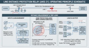 Distance relay protection determines the fault distance by measuring the impedance between the fault point and the protection installation point. It uses the ratio of busbar voltage to line current at the installation point as the measured impedance. This impedance is proportional to the fault distance and is largely unaffected by system operating conditions, ensuring that the protection range remains essentially constant.
Transmission Line Protection Distance Relays, Setting List
| No. | Setting Name | Setting Range (IN=1A or 5A) | Unit | Remarks |
|---|---|---|---|---|
| 1 | Variation Starting Current Setting | (0.05 ~ 3)IN | A | |
| 2 | Line Positive Sequence Impedance Setting | (0.05~655)/In | Ω | |
| 3 | Line Positive Sequence Impedance Angle | 30°~89° | – | |
| 4 | Total Line Length | 0~655 | km | |
| 5 | Phase Distance Zone I Setting | (0.05~125)/In | Ω | |
| 6 | Phase Distance Zone II Setting | (0.05~125)/In | Ω | |
| 7 | Phase Distance Zone II Time Delay | 0.01~10 | s | |
| 8 | Phase Distance Zone III Setting | (0.05~125)/In | Ω | |
| 9 | Phase Distance Zone III Time Delay | 0.01~10.00 | s | |
| 10 | Overcurrent Zone I Setting | (0.05 ~ 20)IN | A | |
| 11 | Overcurrent Zone I Time Delay | 0 ~ 10 | s | |
| 12 | Overcurrent Zone II Setting | (0.05 ~ 20)IN | A | |
| 13 | Overcurrent Zone II Time Delay | 0.1 ~ 10 | s | |
| 14 | Overcurrent Zone III Setting | (0.05 ~ 20)IN | A | |
| 15 | Overcurrent Zone III Time Delay | 0.1 ~ 10 | s | |
| 16 | Overcurrent Undervoltage Setting | 10 ~ 100 | V | Line Voltage |
| 17 | Overcurrent Negative Sequence Voltage Setting | 2 ~ 57 | V | U2 |
| 18 | Zero-sequence Overcurrent Zone I Setting | (0.05 ~ 20) | A | |
| 19 | Zero-sequence Overcurrent Zone I Time Delay | 0 ~ 10 | s | |
| 20 | Zero-sequence Overcurrent Zone II Setting | (0.05 ~ 20) | A | |
| 21 | Zero-sequence Overcurrent Zone II Time Delay | 0.1 ~ 10 | s | |
| 22 | Overcurrent Acceleration Setting | (0.05 ~ 20)IN | A | |
| 23 | Overcurrent Acceleration Time Delay | 0.00~ 3 | s | |
| 24 | Zero-sequence Overcurrent Acceleration Setting | (0.05 ~ 20)IN | A | |
| 25 | Zero-sequence Overcurrent Acceleration Time Delay | 0.00~ 3 | s | |
| 26 | PT Broken Line Phase Overcurrent Setting | (0.05 ~ 20)IN | A | |
| 27 | PT Broken Line Phase Overcurrent Time Delay | 0.1 ~ 10 | s | |
| 28 | Overload Setting | (0.05 ~ 20)IN | A | |
| 29 | Overload Time Delay | 1 ~ 3600 | s | |
| 30 | Synchronization Closing Angle | 10°~ 50° | – | |
| 31 | Auto-reclosing Time Delay | 0.1 ~ 10 | s | |
| 32 | High Current Reclosing Block Setting | (0.05 ~ 20)IN | A | |
| 33 | Under-frequency Load Shedding Frequency | 45 ~ 49.5 | Hz | |
| 34 | Under-frequency Load Shedding Time Delay | 0.1 ~ 40 | s | |
| 35 | Under-frequency Slip Block Setting | 0.5 ~ 20 | Hz/s | |
| 36 | Under-frequency Voltage Block Setting | 30 ~ 100 | V | Line Voltage |
| 37 | Under-voltage Load Shedding Voltage Setting | 30 ~ 100 | V | |
| 38 | Under-voltage Load Shedding Time Delay | 0.1 ~ 40 | s | |
| 39 | Voltage Change Rate Block Setting | 10 ~ 200 | V/s | Line Voltage |
| 40 | Power Swing Block Overcurrent | (0.05~20)In | A | |
| 41 | Distance Protection Resistance Setting | (0.05~125)/In | Ω | |
| 42 | Accelerated Distance Zone III Time Delay | 0.0~10 | s |
Outline and Installation Dimensions
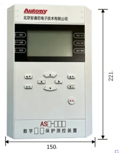
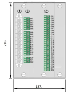
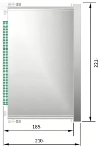
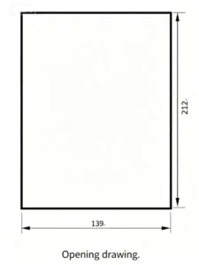 For more information about the ASL-7615 or to discuss your specific project requirements, please contact our technical support team.
How the three distance zones are coordinated
A distance relay measures the impedance between its own location and the fault, then compares that value with the impedance of the protected line. The measurement is reliable near the relay and less reliable at the far end, because arc resistance, mutual coupling and voltage transformer transients all push it off. The line is therefore covered in steps instead of one setting.
| Zone | Reach | Purpose |
|---|---|---|
| Zone 1 | Most of the protected line, short of the remote busbar | Clears close-up faults with no intentional delay |
| Zone 2 | The rest of the line plus part of the next line | Covers the end that zone 1 deliberately leaves out |
| Zone 3 | The remote end of the next line or beyond | Remote backup if the downstream protection fails to operate |
Reach values and time steps are not a property of the relay, they are a property of the network. A zone 1 reach that stops short of the far busbar is standard because the measurement error grows with distance; the exact percentage comes from the line length, the source impedance and the operator’s protection policy, and it is fixed in the coordination study before the relay is configured. The same applies to whether zone 3 is enabled at all, since in a tightly meshed network the downstream protection may already cover that fault. The zone 1, 2 and 3 setting guide works through a numeric example.
Mho or quadrilateral characteristic
The characteristic is the shape of the trip region on the resistance and reactance plane, and the two common shapes fail in different ways.
| Aspect | Mho | Quadrilateral |
|---|---|---|
| Resistive faults | Under-reaches when arc resistance is high | Resistance and reactance set separately, so the reach holds |
| Heavy load | Inherently less affected | Needs a load encroachment setting |
| Line length | Good on short lines with a strong source | Better where the resistive component dominates |
| Setting effort | Reach and angle | Resistance, forward reactance, reverse reactance, angle |
| Direction | Directional by construction | Needs a separate directional element |
On a short line fed from a strong source a mho element is usually the simpler choice and load does not trouble it. On a long line, a line carrying heavy transfer, or one where a fault at the remote end shows a large arc resistance, a quadrilateral element keeps the reach where it belongs because the resistance boundary can be pushed out without moving the reactance boundary. Before choosing, look at what the fault study says about arc resistance at the far end; a quadrilateral element will reach faults a mho element misses, but only if its load encroachment limit is set correctly.
Load encroachment and power swing blocking
A distance element measures impedance, and a heavily loaded line presents an impedance that can look like a fault. As load rises and voltage falls the load point moves into the trip region, and a relay with no load encroachment characteristic will trip a healthy line. The countermeasure is a boundary inside the trip region that the load point is not allowed to cross.
A power swing is a different event with the same symptom. After a disturbance the generators swing against each other, and the impedance seen by the relay moves through the trip region slowly enough that the rate of change identifies it as a swing rather than a fault. Power swing blocking holds the distance elements while the impedance travels at that rate. An out-of-step function decides the case where the swing will not recover and the system has to be split deliberately instead of collapsing.
Both settings belong to the network operating limits, not to the relay alone. A blocking boundary that is too wide leaves the line unprotected during a genuine fault; one that is too narrow trips on the first heavy transfer. Where the application calls for full duplication of the line protection instead, a line differential relay compares both ends over a communication channel and does not depend on the impedance measurement at all.
FAQ
Q1: What voltage levels is the ASL-7615 designed for?
The ASL-7615 is typically designed for transmission and distribution lines up to 110 kV. For specific voltage level selection, please refer to your project requirements.
Q2: What communication protocols are supported?
Standard configurations typically support IEC 61850, Modbus, and other mainstream protocols for integration into digital substations. The actual protocol stack depends on the factory configuration, different models may be equipped with different interface combinations as standard.
Q3: Does the relay support auto-reclosing?
Yes. The relay typically integrates auto-reclosing functionality, supporting single-phase, three-phase, and combined reclosing schemes to meet various system restoration strategies.
Q4: Can the relay be customized?
Yes. Hardware and software customization is available. Protection logic, communication interfaces, and the number of binary inputs/outputs can be tailored to project requirements. Please consult our sales or technical support team for details.
Q5: What information is required for quotation?
To provide an accurate quotation, the following information is typically required:
CT/PT Parameters: Ratios, rated current, etc.
Protection Function Requirements: Number of protection zones and backup protection needs
Communication Interface Requirements: Specific protocols and physical port types
Installation and Power Supply Conditions: Panel dimensions and DC supply voltage
Q6: Can you provide technical support for relay settings?
Yes. We provide comprehensive technical support, including setting guide, logic configuration, and on-site commissioning. For specific projects, offline setting software may also be available. Please contact our technical support team for recommended settings tailored to your system.
Q: How do I place an order?
Send your specification through the contact form, by email to sale@relayprotect.com or on WhatsApp. We check the rating, the protocol and the wiring against your application, confirm the model, and return a quotation. No account or registration is needed.
Q: What is the minimum order quantity?
The minimum order quantity is one unit. A single unit can be ordered for evaluation or for a pilot installation, and project quantities are quoted separately.
Q: What is the lead time?
Standard models ship in 7 to 15 working days after the order is confirmed and payment is received. Custom ratings, protocols or mounting arrangements are confirmed in writing before the order is placed, so the delivery date is known in advance.
Q: Which payment methods and trade terms do you accept?
Payment by T/T, L/C, Western Union or PayPal. Trade terms are EXW, FOB, CIF and DDU. Every relay carries a 12-month warranty.
Need pricing, a datasheet or a wiring drawing?
Tell us your application – rated voltage, CT/VT ratios and the protection functions you need – and we will send a quotation with the matching model. Free technical guidance, parameter setting and commissioning support included.
MOQ 1 unit for samples | Bulk orders ship in 7-15 working days | 12-month warranty | EXW, FOB, CIF, DDU | Payment by T/T, L/C, Western Union or PayPal. New to ordering? See how to order – process, MOQ and lead time.
Related products
High Quality
Stable performance, reliable design, ensuring safe operation for power system protection and grid stability.
Fast Delivery
Timely delivery to support your urgent orders and project schedules efficiently and professionally at any time.
Best Warranty
Professional Warranty: Reliable after-sales support for stable relay protection and long-term customer satisfaction.
Reviews
There are no reviews yet.