

-
Leon Zhang sales consultant
-
Email: zxl635973785@gmail.com
-
Phone/WhatsApp: +86 13655813266
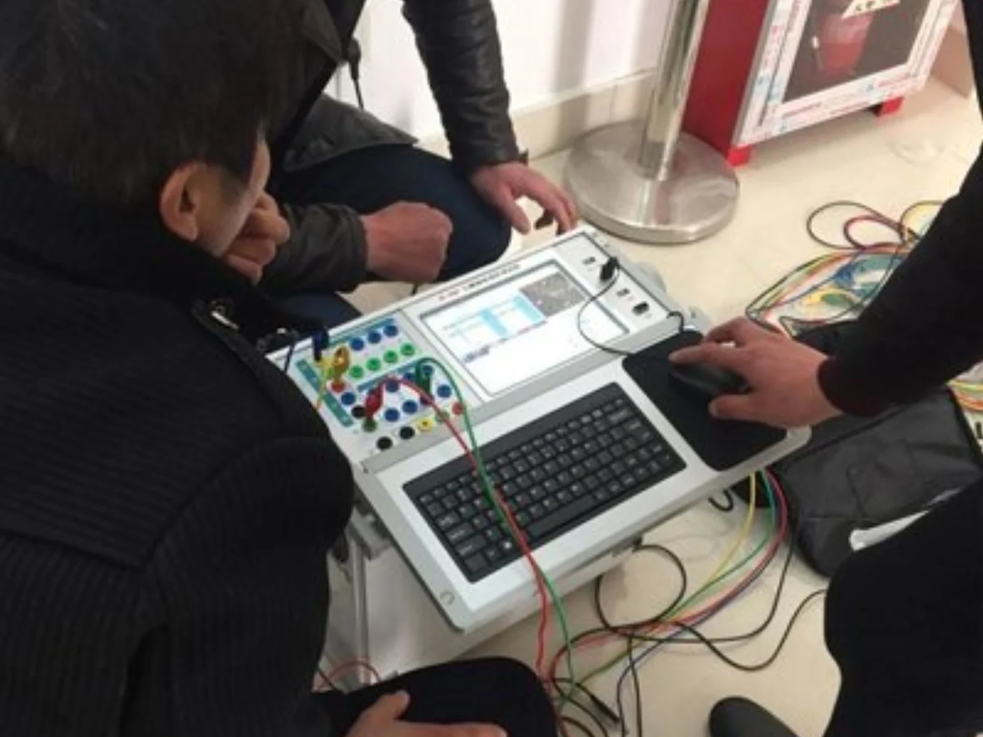
Experiences in relay protection training
Relay protection training is the structured practice that turns a protection engineer from someone who can read a setting sheet into someone who can prove a relay will trip. It has two halves: theory covering protection principles, product families and schematic reading, and experiments covering accuracy checks and function tests with a secondary injection set.
The two halves fail in different ways. Theory that stops at the manual produces engineers who can configure a relay but cannot tell whether a reading is real. Experimental practice without theory produces test reports that pass every injected value and still miss a reversed CT polarity. Training has to hold both, because the field does not separate them.
A test set tells you what you injected. Only the schematic tells you what it means.
At a Glance: What the Training Covers
- Two halves: theory first (principles, products, schematic reading), then experiments (accuracy, function tests).
- ANSI device numbers are the working vocabulary: 50/51 overcurrent, 87 differential, 21 distance, 51N/51G earth fault.
- Schematic reading comes before testing, because secondary circuits do not read as easily as primary ones.
- Test sets need a valid calibration certificate; accuracy experiments check that the relay reads what is injected.
- Function experiments follow the logic diagram in the product manual, not a generic checklist.
- CT polarity is the most common wiring fault, and it shows up as a relay that refuses to operate on a real fault.
- Transformer differential setting is the hardest module: five formulas before a single quantity is injected.
- Safety comes first: isolation, no reverse charging, and never an open-circuited CT secondary.
The function numbers used below follow IEEE C37.2-2022. Relay performance requirements come from IEC 60255-1:2022, and the instrument transformer behaviour that makes polarity and ratio matter comes from IEC 61869-2:2012.
Protection Functions and Practice Stages
Protection relay training experience tends to converge on the same short list of functions, whatever the product. The protection engineer skills that matter here are reading the schematic, choosing the injected quantity, and judging the result, in that order.
| ANSI | Function | Where it appears in training | What the test checks |
|---|---|---|---|
| 50/51 | Instantaneous and time-delayed overcurrent | Feeder and motor relays, three-stage settings | Pickup value, time delay, characteristic curve |
| 51N/51G | Earth fault overcurrent | Residual current path and CT residual connection | Pickup against injected residual current |
| 87T / 87G | Transformer and generator differential | The hardest module; five setting formulas first | Bias slope, second harmonic restraint, operating current |
| 21 | Distance | Line relays | Impedance reach and zone timing |
| 49 | Thermal overload | Motor and transformer relays | Trip time against the thermal model |
| 40 | Loss of excitation | Generator relays | Impedance entering the under-excitation zone |
| 27/59 | Undervoltage and overvoltage | Bus and generator relays | Pickup and drop-off ratio |
| 63 | Non-electrical quantity (gas, temperature) | Transformer protection cabinets | Contact input to trip, not a measured quantity |
| 64R | Rotor earth fault | Generator excitation circuits | Injection voltage method, single versus two point fault |
The table maps functions that already appear in this training onto their device numbers. It adds no function that the training does not already cover; it only gives each one the name used on drawings and setting sheets.
Those functions are then practised in a fixed order. Skipping ahead is what produces engineers who can run a test set but cannot say why a result is wrong.
| Stage | What you practise | Equipment and documents | Pass criterion |
|---|---|---|---|
| Basic knowledge | Protection principles and operating logic | Manuals, IEC and IEEE standards | You can explain the logic without opening the manual |
| Products | Which device protects which object, by voltage level | Manufacturer manuals and drawings | You pick the right device for the protected object |
| Schematic reading | Secondary circuits, symbols, numbering | Secondary schematic drawings | You trace the trip circuit end to end |
| Test set handling | Calibration validity and safe operation | Secondary injection set with current certificate | Injected value and relay reading agree within the allowed error |
| Accuracy experiments | Voltage and current sampling, relay calibration | Test set and relay display | Displayed value stays inside the allowed error band |
| Function experiments | Enable functions, set thresholds and CT/PT ratios, follow the logic diagram | Test set and product manual | The relay trips on the logic it was configured to |
Relay Protection Training: Theory Part
Understand basic knowledge
Manuals before devices.
It is necessary to understand the industry’s basic knowledge in advance and learn the principles of protection operation.
For example, common protections include three-stage overcurrent protection, differential protection, overload protection, overvoltage protection, loss-of-excitation protection, etc. You need to understand the protection logic and principles of these common protection functions.
Only by understanding these can we lay the foundation for later product familiarity.
Know the products
Products differ. Principles do not.
There are many types of relay protection products. Different protection objects and different voltage levels have different protection products.
For example, for transformers, common products include transformer differential protection, transformer backup protection, transformer non-electrical-quantity protection, etc.
For generator sets, common ones include generator differential protection, generator backup protection, and generator rotor-grounding protection. Different products are applied in different places and protect different objects, so the product range has to be learned against industry technical standards and not from memory.
It is also worth noting that products from different manufacturers operate somewhat differently, so you must strictly follow the manufacturer’s manual and drawings.
Learn to read power schematic diagrams
Read the drawing before you inject.
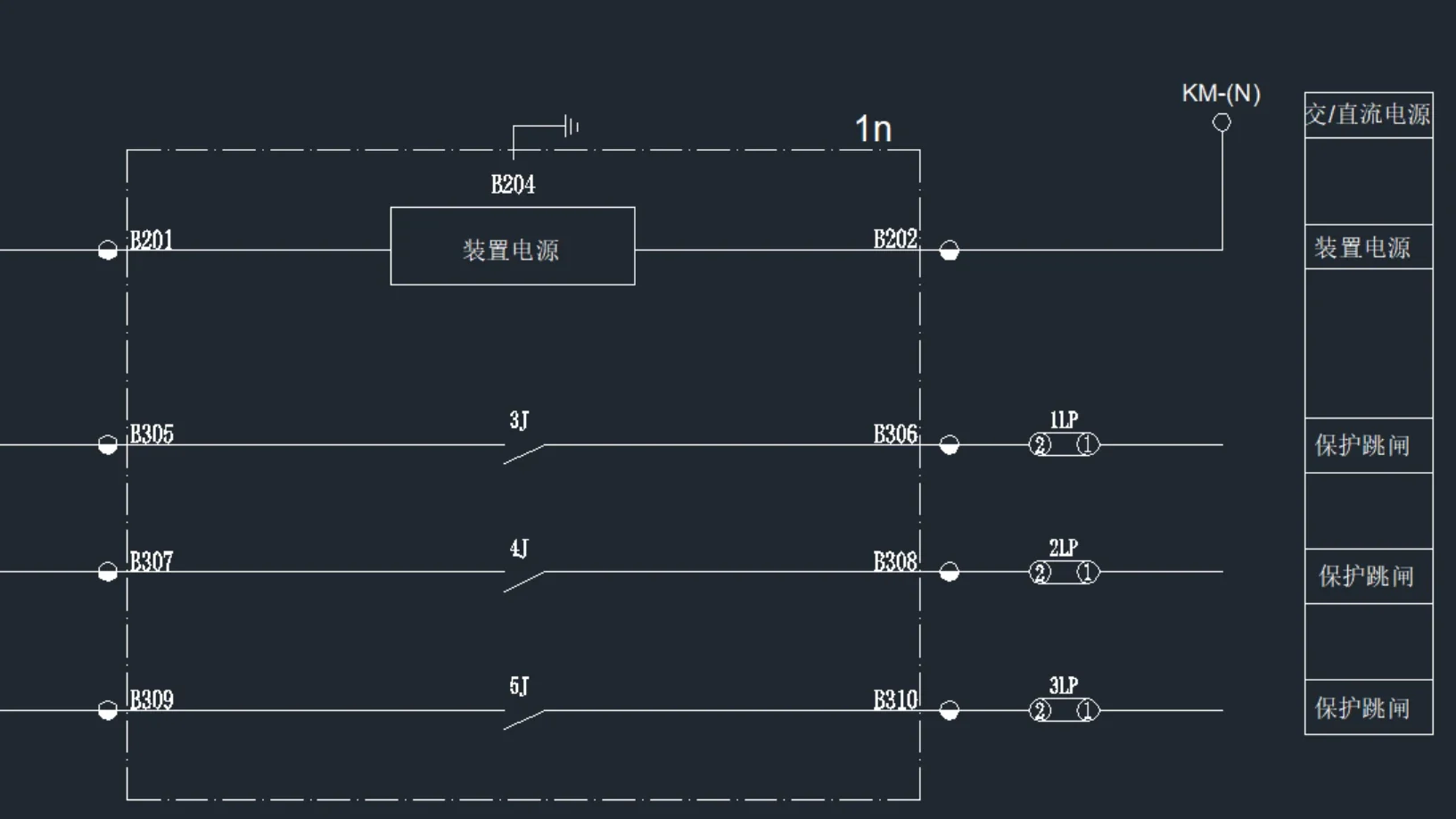
It is very necessary to learn to read secondary electrical schematic diagrams, because secondary control diagrams are not as intuitive as primary diagrams. You must understand the principles, recognize product symbols, and understand numbering to read them. By reading the schematics, you can better prepare for subsequent experiments.
Learn to use relay protection test sets
Certificates expire. Check the date.
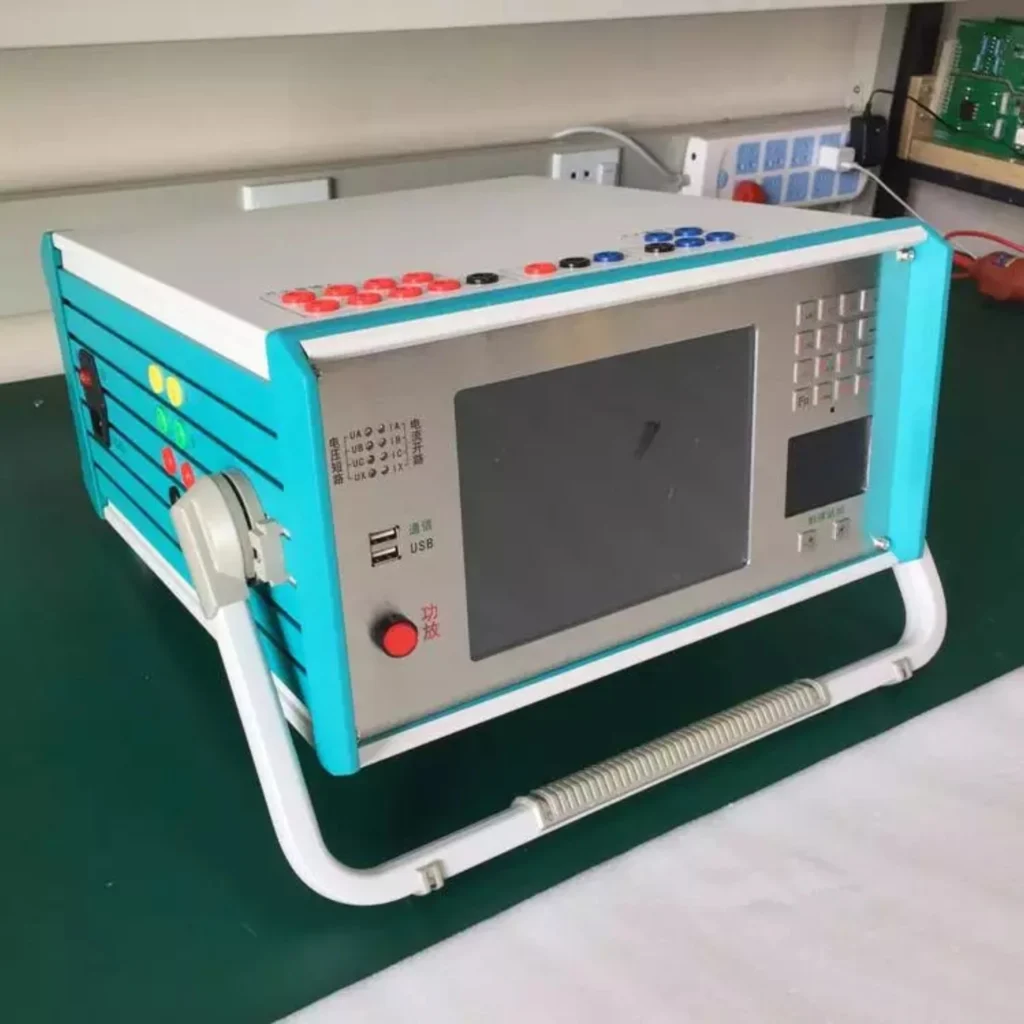
Relay protection experiment regulations require that experimental equipment must meet standards and regulations, operate normally, have corresponding calibration/verification certificates with valid periods, and receive regular maintenance.
One example shows why the schematic has to come first.
In the current protection experiment of relay protection, taking a 10 kV line relay protection device as an example, the electrical schematic clearly marks the wiring relationships of the current transformer (CT), relay, trip circuit, and signal circuit.
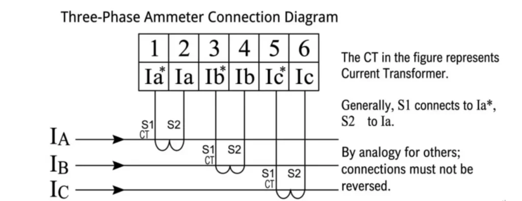
In practice, if wiring is not done according to the schematic and the CT secondary winding polarity is mistakenly reversed, the protection device will sample current in the opposite direction and show the experimental anomaly that gives this fault its name: the device refuses to operate during a fault.
This situation is caused by not performing CT polarity testing. Under normal circumstances, current enters the like-named terminal and exits the unlike-named terminal. After checking against the schematic and correcting the CT polarity wiring, repeating the experiment can achieve accurate operation of the protection device.
Relay Testing Training: Experimental Part
The experimental part of relay protection is very important. Experiments must be conducted according to specifications; only then will the product meet commissioning conditions. If incorrect operations occur during experiments, such as non-standard procedures or improper operations, the product may be directly damaged, or the product may fail to meet operational requirements during service, creating safety hazards for future equipment operation.
Relay Protection Accuracy Experiments
Accuracy first, functions second.
The first task is to perform accuracy experiments, i.e., what we commonly call relay calibration. The accuracy experiment directly reflects the product’s sampling accuracy, mainly including voltage and current. By testing the device with a relay protection test set, the values can be directly and intuitively read from the relay.
The injected quantities from the relay protection tester must be within the allowable error range of the values displayed by the device to be considered qualified. Sometimes, if the displayed values sit outside the band, the device itself can be adjusted and calibrated to bring the accuracy back.
Relay protection function experiments
Order matters here.
This part mainly covers the protection functions of the relay protection, using experimental equipment to debug the protection relay.
To complete this functional experiment, a reliable relay protection test set must be used. The relay protection tester must inject quantities to the electromechanical protections to complete the test. The steps are as follows:
First understand which protection function tests must be done for this product
Relay protection products contain many functions, and testing every one of them wastes time: some of those functions are never commissioned in service. Start from the list the project actually enables.
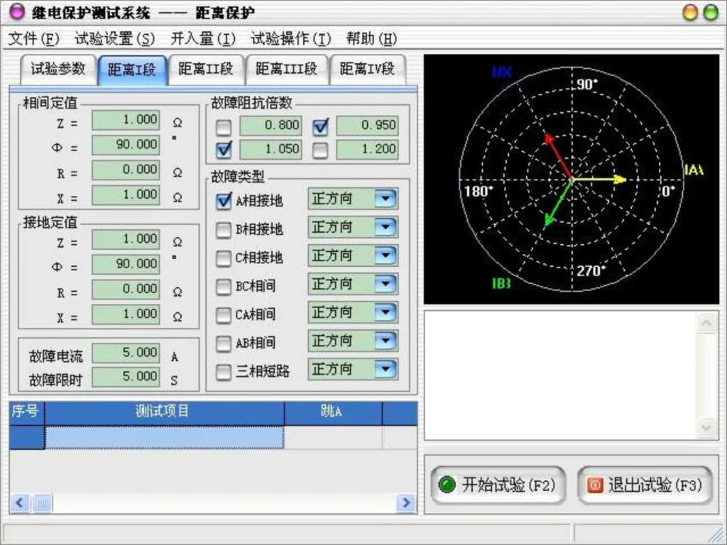
Follow the relay protection training sequence and the product instructions
Before doing the experiment, the product parameters need to be set. This includes enabling/disabling protection functions, setting protection thresholds, CT ratio, PT ratio, etc. After the protection device parameter settings are completed, the protection experiments can be performed.
Refer to the protection operation logic diagram in the product manual
The relay protection manual will describe the protection function operation logic and corresponding descriptions. Conducting experiments according to the logic diagram can ensure reliable device operation.
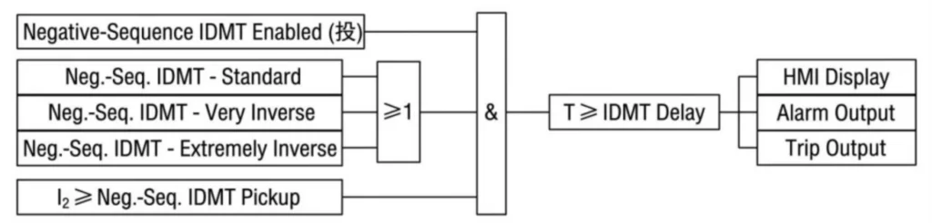
Transformer differential protection experiments are the module that takes longest to learn. The setting calculation has to be done before anything can be injected, and the calculation itself has five parts.
First, you must learn to calculate the setting values for transformer differential protection. A common method is as follows:
Transformer Differential Protection Setting Calculation
Rated current calculation: the secondary rated value worked out from transformer capacity and CT ratio.

CT secondary connection branch current: the current each CT branch contributes once the connection group is fixed.

Second harmonic current: the restraint quantity that blocks operation during transformer inrush.

Minimum pickup current of biased differential protection: the lowest differential current that will operate the biased element.

Differential operating current: the quantity the relay compares against the bias characteristic.

Calculate the secondary rated value using transformer capacity and CT ratio, then enter it into the protection device to complete a series of setting values. Then use a relay protection test set to perform experiments, simulate internal transformer faults, and obtain experimental data. A relay protection test set then simulates internal transformer faults so the calculated values can be checked against measured ones.
FAQ: Relay Protection Training and Testing
What core content is covered in relay protection training?
The training mainly includes basic principles of relay protection, ANSI standard protection functions (50/51 overcurrent, 87 differential, 21 distance, earth fault protection, etc.), wiring of CT/PT secondary circuits, protection setting calculation, equipment parameter configuration, on-site troubleshooting and standard secondary injection testing operations.
Who is this relay protection training suitable for?
It targets substation maintenance technicians, EPC project electrical engineers, power grid operation staff and factory electrical maintenance personnel, along with new technical sales and after-sales engineers who have to explain protection equipment to customers. No prior injection testing experience is assumed.
What is secondary injection testing in relay protection tests?
It is the most mainstream verification method for protection relays. Professional relay testers simulate fault current and voltage signals to inject into the relay, checking whether the device can correctly identify faults, execute trip logic and match preset protection curves.
What standard items must be tested during routine relay protection inspection?
Key test items include the pickup action value, the tripping time delay, the protection characteristic curve, the communication link (IEC 61850, Modbus or IEC 60870-5-103), CT loop anomaly detection, trip output contact reliability, and the fault event recording function. Each item takes its own injected quantity and its own acceptance band.
How long is the general cycle for on-site relay protection testing?
For medium & high voltage substation protection devices, the industry standard maintenance test cycle is 1~5 years; low-voltage distribution relays shall be inspected and tested according to the enterprise’s internal power maintenance management regulations.
What common faults are covered in the troubleshooting part of the training?What common faults will be taught in the troubleshooting part of the training?
It covers false tripping caused by wrong protection settings, refusal to trip under actual short-circuit faults, CT wiring errors leading to protection failure, relay hardware aging and damage, communication interruption between the relay and SCADA system, and grounding faults of secondary control circuits.
What equipment is required to finish relay protection function testing?
The core device is a relay protection tester, also called a secondary injection test set, with a valid calibration certificate. Auxiliary tools include digital multimeters, insulation resistance testers, wiring pliers and the locking tools used for power cut operation. A laptop with the relay setting software is needed for most numerical relays.
Can trainees independently complete relay setting and testing after the training?
Basic training enables trainees to finish conventional feeder, motor and transformer relay parameter setting and simple single-device testing. For complex power grid protection coordination and whole-station linkage test, follow-up technical guidance and project practice are recommended.
What safety rules must be followed during relay protection live testing?
Strictly implement lockout-tagout power isolation procedures before testing; confirm the secondary circuit will not cause reverse charging to primary equipment; mark test wiring clearly to avoid short-circuit or open-circuit faults on CT/PT loops, which may damage transformers and voltage transformers.
What is the difference between offline training and on-site practical training?What is the difference between relay protection offline training and on-site practical training?
Offline courses focus on theoretical principles, specification interpretation and software parameter configuration; on-site training combines real substation equipment to practice wiring, fault simulation, live troubleshooting and tester operation, which is more applicable to actual engineering projects.
Why is relay short circuit protection the key module in training and testing?
Short circuit faults bring the biggest impact to power equipment. Relay short circuit protection is the primary means to cut off fault current rapidly. Training and targeted testing can guarantee the relay trips reliably during short-circuit accidents and prevent equipment burnout or power system accidents.
Can old electromagnetic relays and new numerical protection relays use the same testing methods?
The core secondary injection testing principle is consistent. Electromagnetic relays mainly test coil action and contact output; intelligent numerical relays add more items like firmware version verification, background communication and fault waveform recording detection.
What are the standards for protective relay testing?
Protective relay testing mainly follows the IEC 60255 series for relay performance, the IEEE C37 series for device numbers and testing practice, and GB/T 14598, which is identically adopted from IEC and used alongside it on domestic projects. The table above lists the specific parts referenced on this page.
Conclusion
Relay protection training works when the theory half and the experimental half are taught against the same schematic. Learn the function and its device number, read the drawing that puts it in a circuit, then inject the quantity that proves it. Anything that skips one of those three steps shows up later as a report with no judgement behind it.
If you are building a training plan for a maintenance team, start from the function list above and the six practice stages, then match each line to the relay types you actually operate. Send us that list with your voltage levels and we will map it to the test sets and setting sheets that fit.
Related Reading
- Protection relay testing and commissioning: the six-step sequence a device-level test and a system-level commissioning run follow.
- Protection relay setting calculation: how pickup, time multiplier and bias slope are derived before anything is injected.
- Transformer differential protection setting: the worked version of the five formulas in this page.
- Protection relay troubleshooting: the common fault modes and the checks that find them.
- Protection relay nuisance tripping: eight field causes, from CT saturation to wrong polarity.
- Modbus and IEC 61850 communication protocols: what the communication test item actually verifies.
- Numerical overcurrent protection relay: the 50/51 functions most trainees start on.
- Generator differential protection relay (87G): the generator side of the differential module.
- Line distance protection relay: where the 21 element is configured and tested.
- Differential relay protection: the principle behind 87T and 87G.
Technical References
| Standard | Edition | What it governs | Why it matters in training |
|---|---|---|---|
| IEC 60255-1 | 2022 | Measuring relays and protection equipment: common requirements | Performance and marking requirements the relay is tested against |
| IEEE C37.2 | 2022 | Device function numbers, acronyms and contact designations | The ANSI number vocabulary used on drawings and setting sheets |
| IEC 61869-2 | 2012 | Additional requirements for current transformers | Why CT polarity and ratio decide whether an injected test means anything |
| IEEE C37.233 | check current edition | Guide for power system protection testing | Test planning and documentation practice |
| IEEE C37.90 | check current edition | Withstand requirements for relays and relay systems | What the relay must survive, not what it must measure |
| IEC 61850-8-1 | 2011+AMD1:2020 | Specific communication service mapping | What the station bus test item verifies |
| IEC 60870-5-104 | 2006+AMD1:2016 | Network access for IEC 60870-5-101 over standard transport | Protocol item in the communication check |
| GB/T 14598 | check current edition | Domestic equivalent, identically adopted from IEC 60255 | Referenced alongside IEC on Chinese projects |
Edition years change. Confirm the current edition against the publisher catalogue before quoting a standard in a test plan.



About Author

Hello, I'm Leno Zhang. I have 15 years of experience in the power relay protection industry with extensive pre-sales and after-sales project experience. Our company specializes in various complete sets of relay protection and automation equipment. I can assist customers in solving all practical on-site project challenges and provide optimal integrated solutions.
Tell Us Your Requirement
High Quality
Stable performance, reliable design, ensuring safe operation for power system protection and grid stability.
Fast Delivery
Timely delivery to support your urgent orders and project schedules efficiently and professionally at any time.
Best Warranty
Professional Warranty: Reliable after-sales support for stable relay protection and long-term customer satisfaction.