

-
Leon Zhang sales consultant
-
Email: zxl635973785@gmail.com
-
Phone/WhatsApp: +86 13655813266
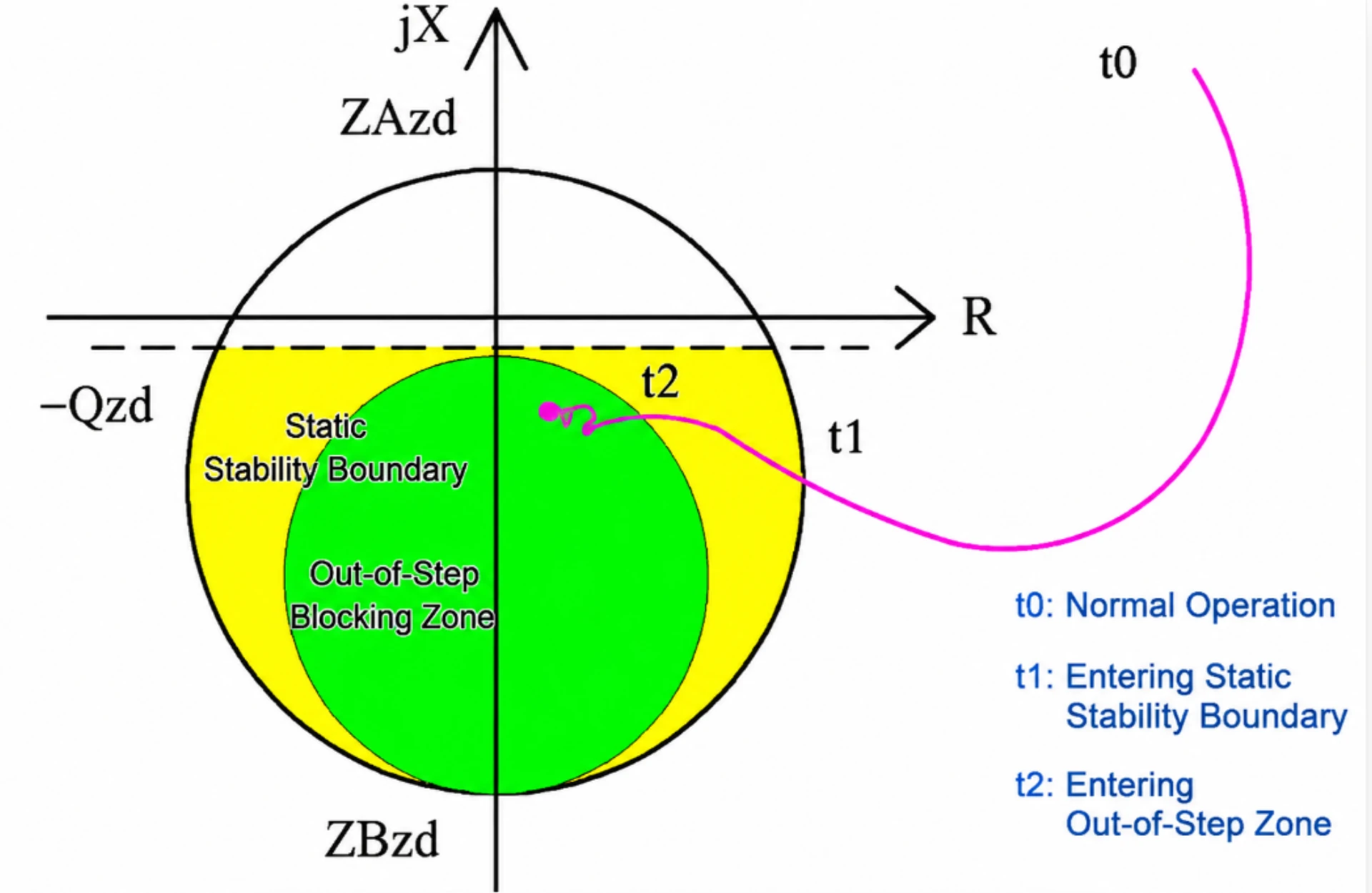
ANSI 40 Loss of Excitation Protection: Principle and Relay Selection
Loss of excitation protection (ANSI 40) detects the loss or collapse of a synchronous generator field current and trips the unit before the rotor overheats. The relay watches the R-X impedance seen at the generator terminals and operates when the trajectory enters an offset mho or admittance characteristic.
Written by Leon Zhang, Protection Application Engineer · Technical review by Li Ming, Electrical Engineer · Last reviewed October 2026
At a Glance: What an ANSI 40 Relay Covers
- ANSI 40 loss of excitation: complete or partial loss of field current on a grid-connected machine.
- Most common cause: AVR or exciter failure, excitation breaker opening, field circuit open.
- What the relay measures: terminal impedance, terminal voltage, reactive power, field current.
- Where it sits on the R-X plane: inside an offset mho circle drawn into the third quadrant, where both R and X are negative.
- Stage 1: light or partial underexcitation, alarm only.
- Stage 2: sustained full excitation loss, delayed trip.
- Why any delay exists: a short swing must not clear the unit, and the trip has to stay ahead of the rotor thermal limit.
- Norm it sits in: IEEE C37.102-2023 on excitation loss, with ANSI/IEEE C37.2-2022 device numbering.
Why a Generator Breaker Cannot See Excitation Loss
A generator breaker trips on current, on voltage, or on a protection command. None of the three tells you the field is gone. A machine can stay on the bus with the field open for minutes, and the only visible sign is the reactive power reversing.
That reversal is the real signal. Once the field collapses the unit stops supplying reactive power and starts absorbing it, so it behaves like a large inductive load hung on the bus. Stator current rises, terminal voltage falls, and the rotor picks up eddy-current heating that no current-only element will catch in time.
Where ANSI 40 Sits in the Generator Suite
An ANSI 40 element is one of the standard generator function numbers in ANSI/IEEE C37.2-2022. It works beside ANSI 32 reverse power, ANSI 24 overexcitation (a V/Hz element) and ANSI 21G generator impedance. Each covers a different failure, and they overlap on purpose: 32 catches the machine motoring, 24 catches too much field, 21G catches stator electrical faults, and 40 catches the field itself going away. Plants already running a plant control layer usually start from the automation system for power plant generator sets, and the commissioning practice below lines up with relay protection training and testing.
The sections below cover what ANSI 40 sees, how the detection is drawn on the impedance plane, how both stages are set, and how to commission and select the relay.
What Is Loss of Excitation Protection?
The ANSI 40 function is a dedicated generator protection logic that detects complete or partial excitation failure of a synchronous machine. Unlike general overcurrent or overvoltage protection, it targets states those functions cannot see: field current gone while the stator still carries load current.
A healthy synchronous generator relies on DC excitation current to build a stable rotor magnetic field, maintaining terminal voltage and controllable reactive power exchange with the grid. Once excitation is lost or severely attenuated:
- Generator terminal voltage drops sharply
- The generator transitions from reactive power output to reactive power absorption from the grid
- Rotor magnetic flux decays rapidly, triggering asynchronous operation
- Stator and rotor windings generate excessive eddy current heat
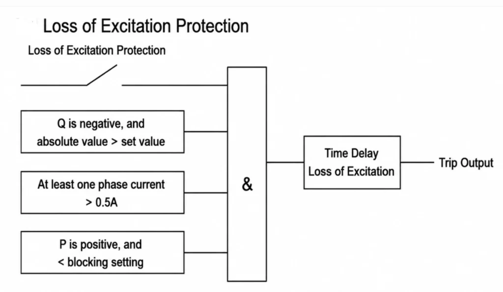
The ANSI 40 element continuously monitors the impedance trajectory, terminal voltage, reactive power and field current. It gives an alarm or a trip once those quantities cross their limits, which closes the blind spot left when overcurrent and undervoltage elements work on their own. Any of them alone leaves a gap: field loss produces no overcurrent until the machine has already started absorbing reactive power.
Core Risks of Unresolved Generator Loss of Excitation Faults
Field statistics show that delayed response to excitation loss faults is one of the top causes of permanent generator damage and regional grid voltage collapse. The following three risks are why the element is mandatory rather than optional:
- Generator Permanent Damage: Long-term asynchronous operation causes rotor winding overheating, insulation aging, and mechanical vibration fatigue, leading to costly overhaul or unit replacement.
- Grid Stability Failure: Massive reactive power absorption by faulty generators pulls down system voltage, easily triggering cascaded tripping of transmission lines and transformers in weak grid systems.
- Project Economic Losses: Unplanned shutdowns disrupt EPC project commissioning progress and stable power supply for industrial and commercial loads, resulting in substantial operational losses.
Common Causes of Generator Loss of Excitation
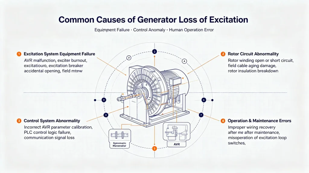
Loss of excitation faults in synchronous generators mainly stem from four field-verified causes, covering equipment failure, control anomaly, and human operation errors:
Excitation System Equipment Failure
AVR (Automatic Voltage Regulator) malfunction, exciter burnout, excitation breaker accidental opening, and field main circuit open circuit are the most frequent root causes in operational power plants.
Rotor Circuit Abnormality
Rotor winding open/short circuit, field cable aging damage, and rotor insulation breakdown will directly interrupt normal excitation current transmission.
Control System Abnormality
Incorrect AVR parameter calibration, PLC control logic failure, and communication signal loss between upper computers and excitation devices will cause abnormal excitation attenuation.
Operation & Maintenance Errors
Improper wiring recovery after equipment maintenance and misoperation of excitation loop switches are common human-induced faults in new EPC project commissioning stages.
Working Principle of Loss of Excitation Protection
Modern numerical relays use the offset mho characteristic on the R-X plane. That is the approach IEEE C37.102 gives for excitation loss on a synchronous machine, and it holds for steam, hydro and industrial sets alike. A simple undervoltage or undercurrent element will not do the job, because both quantities are disturbed by the grid long before the field actually goes.
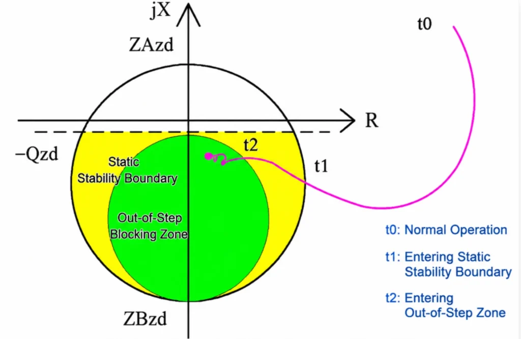
Impedance Trajectory Detection (Core Logic)
When a machine loses excitation the measured impedance moves across the R-X plane and enters the ANSI 40 zone. A healthy unit sits with positive reactance because it exports reactive power. After the field is gone the machine absorbs reactive power, so the reactance goes negative and the point sweeps into the third quadrant, which is exactly where the offset circle is drawn. The relay resolves positive-sequence voltage and current, forms the apparent impedance, and decides whether the point really landed inside the characteristic. A synchronous generator excitation loss never arrives as an overcurrent, which is why the impedance test is the one that copes with it.
Multi-Criterion Auxiliary Verification
Two conditions put the measured point in the wrong place. A system short circuit collapses terminal voltage, which drives the apparent impedance toward the origin even with the field intact, so the element needs voltage memory or a blocking condition during faults. Heavy load on a weak grid can push the point close to the R axis, which is why the offset is taken from the load impedance instead of guessed.
Mainstream relays add auxiliary criteria behind the impedance test. Three are common: reverse reactive power, field current below minimum, and an undervoltage lock during external faults. The element should block on one of them during a fault; a relay that trips the unit anyway is not doing what its datasheet says.
ANSI 40 Protection vs. Overexcitation Protection: Key Differences
Engineers often confuse the two field-related generator functions. 40 and 24 are not the same element and they are never set from the same data:
| Comparison Item | Loss of Excitation Protection | Overexcitation Protection |
|---|---|---|
| ANSI Standard Code | ANSI 40 | ANSI 24 |
| Core Fault Condition | Partial/complete loss of field current | Excessive rotor magnetic flux and over-excitation |
| Main System Hazard | Reactive power inversion, grid voltage collapse, generator asynchronous operation | Stator core overheating, insulation aging, magnetic saturation |
| Detection Principle | R-X plane impedance trajectory + reactive power monitoring | V/Hz ratio over-limit detection |
| Main Application Scenario | Synchronous generator grid-connected operation | Generator-transformer unit overall protection |
Key Setting & Commissioning Guidelines for Field Engineers
Stage values come from the inputs in the table above. IEEE C37.102-2023 is the reference for both the characteristic shape and the delay:
Setting Inputs and Where they Come From
Every offset mho diameter is derived from machine data, not picked from a preset list. Four inputs cover most cases:
| Input | Where the value comes from | What it defines | Recheck when |
|---|---|---|---|
| Synchronous reactance Xd | Nameplate or an IEEE 115-2019 test report | Outer reach of the ANSI 40 characteristic | The machine is rewound or re-rated |
| Transient reactance Xd′ | Nameplate or an IEEE 115-2019 test report | Inner boundary used for the alarm stage | The unit is restarted after a long outage |
| Bus short-circuit impedance Zs | Fault-level study for the generator bus | How far the characteristic may reach toward the grid | The bus or coupling configuration changes |
| Rated stator current and loading | Machine nameplate | R-axis offset that keeps load current outside the zone | The plant load profile is revised |
Protection Zone Calibration
Set the two stages from the synchronous reactance Xd and the transient reactance Xd′, together with the short-circuit impedance of the bus. Stage 1 covers light-load excitation loss and raises an alarm. Stage 2 covers the full-load case and trips.
Time Delay Matching
Use two delays: a short one for the alarm and a long one before the trip. The long delay has to outlast the swing the unit is expected to ride through, otherwise a stable power swing clears the machine for nothing. Both delays are then checked against the rotor thermal limit so the element still acts before the winding heats up. Tripping on transients is the usual reason a stage 2 delay is added at all. Swing and fault are not the same event.
Standard Commissioning Steps
- Verify CT/PT wiring accuracy and parameter consistency
- Upload customized generator parameters and ANSI 40 protection logic
- Complete secondary injection testing: inject impedance just inside the set boundary and confirm operation, then just outside and confirm restraint
- Check trip loop linkage and remote communication signal output
- Record test data and generate standardized commissioning reports
How to Select a Qualified Loss of Excitation Protection Relay
40 relay selection for an overseas job starts with four checks: the relay must resolve the impedance seen at the machine terminals, carry the ANSI 40 logic without a separate electromechanical element, expose both the alarm and the trip stage, and record the trip cause for the operator. What to ask the supplier follows.
Standardized Protection Function Integration
Integrate the full generator function list around the ANSI 40 element: 32 reverse power, 50/51 overcurrent, 87G generator differential, and 27/59 over- and undervoltage. A machine fitted with only the 40 function still has a hole in it, because nothing else watches the breaker staying open after the field returns.
Communication Protocol Compatibility
The relay should carry IEC 61850, Modbus TCP/IP and IEC 60870-5-103 and hand the ANSI 40 alarm and trip bits to the station bus. Check the protocol list in substation communication protocols before ordering, because a plant already running IEC 61850 GOOSE needs the trip output mapped, not only the measurement points.
Professional Full-Lifecycle Technical Support
Send the machine rating, the CT and VT ratios and the exciter type, and the engineering team returns a setting file for the elements that apply. Factory acceptance testing covers both ANSI 40 stages on secondary injection, and that report is what the site engineer repeats on arrival.
FAQ
1. What is the standard industry name for generator excitation loss protection?
The official standard terms are loss of excitation protection and loss of field excitation protection, uniformly corresponding to ANSI 40 protection function in global power engineering.
2. What failures will occur if a generator lacks ANSI 40 protection?
Without a working ANSI 40 element the unit runs until the rotor insulation gives out, and the grid sees voltage fall until other machines react. Out-of-step splitting usually follows that, not the other way round.
3. Is impedance-based detection the only working principle for ANSI 40 protection?
Impedance trajectory detection is the core principle, and the only one that works on a machine already tied to the grid. Reactive power and voltage criteria are layered on top of it, and they are what keep the element from operating during a system fault.
4. What is generator distance relay (ANSI 21G)?
Generator distance relay, designated ANSI 21G, is also known as generator under-impedance protection. It continuously calculates apparent impedance at generator terminals. When the measured impedance falls within the predefined operating characteristic, the relay identifies short-circuit faults on generator leads, bus duct and step-up transformer, It acts as main or backup phase fault protection for generator-transformer unit.
Conclusion
Loss of excitation protection is one of the few generator functions where the relay has to understand the machine rather than just the current. Set both stages from Xd, Xd′ and the bus fault level. Keep the trip delay behind the swing but ahead of the rotor limit, and prove both stages on secondary injection before the unit is energised. Hydropower and thermal units are commissioned the same way.
For an overseas EPC contractor the order starts with the setting file, not the datasheet. Send the machine rating and the exciter type, and the relay comes specified for the 40, 32 and 24 elements together.
Our relays are tested on secondary injection before shipment, and the commissioning report carries the same ANSI 40 boundaries the site will see on arrival.
Related Reading
Three places to read next follow, each picking up a different part of the generator protection picture: generator protection relay covers the whole function list around the ANSI 40 element, out of step protection covers what happens once the unit loses synchronism, and the 87G/50/51 relay covers the fault-current side that ANSI 40 never sees.
Technical References and Sources
| Source | What it covers | Type | Edition |
|---|---|---|---|
| ANSI/IEEE C37.102-2023 | AC generator protection, including the excitation loss chapter and the offset mho setting basis | IEEE guide | 2023 |
| IEEE 115-2019 | Test procedures for synchronous machines, including rotor and excitation measurements | IEEE guide | 2019 |
| ANSI/IEEE C37.2-2022 | Device function numbers, ANSI 40 loss of excitation | IEEE standard | 2022 |
| ANSI/IEEE C37.110-2023 | Application of current transformers for protective relaying, used by the impedance element | IEEE guide | 2023 |
| IEC 60255-1:2022 | Measuring relays and protection equipment, general requirements | IEC standard | 2022 (Ed. 2.0) |
| IEC 61869-2:2012 | Current transformers, additional requirements on CT accuracy | IEC standard | 2012 |



About Author

Hello, I'm Leno Zhang. I have 15 years of experience in the power relay protection industry with extensive pre-sales and after-sales project experience. Our company specializes in various complete sets of relay protection and automation equipment. I can assist customers in solving all practical on-site project challenges and provide optimal integrated solutions.
Tell Us Your Requirement
High Quality
Stable performance, reliable design, ensuring safe operation for power system protection and grid stability.
Fast Delivery
Timely delivery to support your urgent orders and project schedules efficiently and professionally at any time.
Best Warranty
Professional Warranty: Reliable after-sales support for stable relay protection and long-term customer satisfaction.