

-
Leon Zhang sales consultant
-
Email: zxl635973785@gmail.com
-
Phone/WhatsApp: +86 13655813266
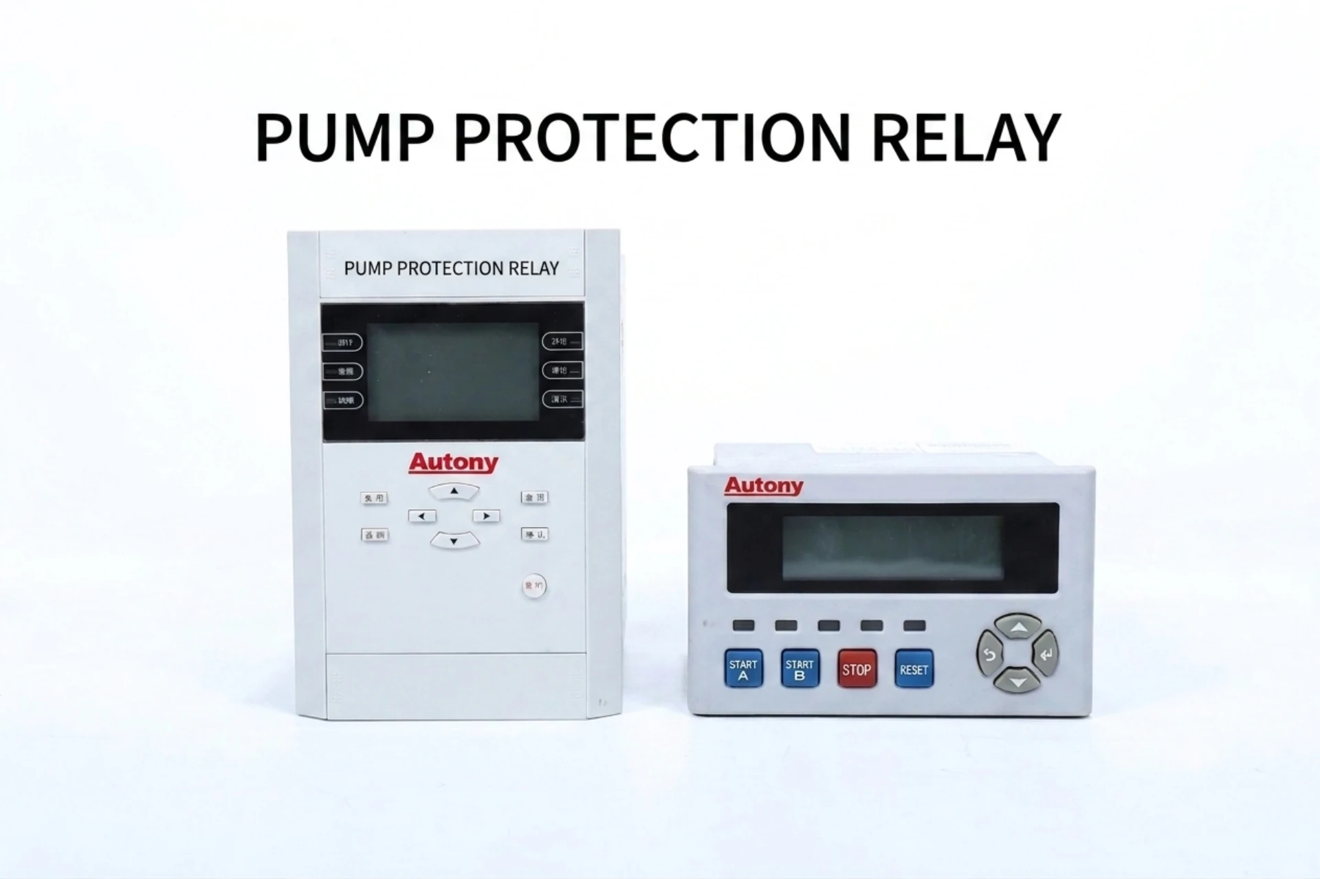
Pump Protection Relay: Complete Selection Guide for Industrial Pump Motors
Pump protection relays are motor protection devices set up for pump duty: they trip on dry running, overload, phase loss, jamming and earth fault before the motor or the mechanical seal is destroyed. The ANSI functions behind those trips are the same numbers used on any motor feeder, but the settings are not.
A general motor protection relay will run a pump. It will not catch a dry run, because it has no undercurrent element, and a pump running dry looks exactly like a healthy, lightly loaded motor.
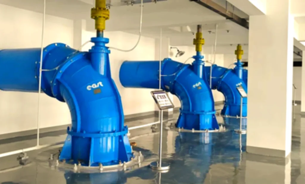
At a Glance: Pump Protection Relay Functions by ANSI Number
Eight functions cover what actually destroys a pump motor. The numbers are the same ANSI/IEEE C37.2 device numbers used on any motor feeder; what changes on pump duty is which ones get enabled and how they are set.
- 37, dry running: the pump loses suction and motor current falls to roughly 30 to 60 percent of full load. The relay trips on undercurrent before the mechanical seal runs dry.
- 49, overload: a blocked impeller or a throttled discharge holds current above the thermal curve. The relay trips on the modelled winding temperature, not on raw amps.
- 46, phase loss and unbalance: losing one phase raises negative-sequence current sharply, and the winding heats far faster than load current suggests. Trip is in milliseconds.
- 47, phase sequence: after a supply change a pump can run backwards and still show normal current. The element blocks the start instead of tripping after the fact.
- 48 and 51LR, locked rotor: a jammed impeller draws starting current with no rotation. The stall timer trips before the winding melts.
- 50 and 51, short circuit: phase-to-phase faults on the feeder or in the terminal box, cleared on instantaneous or inverse-time current.
- 51N, earth fault: insulation breakdown to the pump body or a wet cable joint, picked up by a core-balance CT.
- 66, starts per hour: limits how often the pump restarts. On a level-controlled station with a small wet well this is the element that saves the motor.
Three documents set the boundaries for that hardware. IEC 60255-1:2022 covers the general requirements for the relay, IEC 60255-149:2013 covers the thermal model behind the 49 function, and IEEE C37.96-2012 is the AC motor protection guide most pump specifications are written against. The device numbers come from ANSI/IEEE C37.2-2022.
The sections below go through what the relay is, which faults it answers, how the product ranges split by voltage, what to send a supplier to get a priced relay schedule, and how the relay talks to the pump station PLC.
Numbers first, then settings.
What is a Pump Protection Relay?
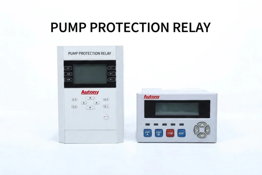
A pump protection relay is a dedicated intelligent protection device designed exclusively for water pump units in pump stations, sewage plants, water supply and drainage automation systems.
The difference from a general motor protection relay is the input list and the trip logic, not the hardware. Pump duty adds undercurrent for dry running, a stall timer for jamming, and usually a level or flow interlock from the PLC; it also assumes long starts and repeated duty cycles that a conveyor or fan motor never sees.
Most units mount in the pump MCC or in the pump station LCU cabinet, take their current from three CTs or an integrated current input, and hand one trip contact to the starter plus one alarm contact to the PLC.
One CT per phase. Nothing shared.
Common Pump Problems and How the Relay Answers Them
Five failure modes account for almost every pump motor that comes back to the workshop. Each one has a different signature on current, so each one needs a different element. Matching the fault to the element is the whole job.
Dry Running (Most Common Fault)
- Causes: Low water level, empty tank, blocked suction pipe/strainer, or improper installation leading to no-load operation.
- Consequences: No cooling or lubrication → mechanical seal dry wear, bearing overheating, stator burnout, and in severe cases, pump body damage.
- What the relay does: Uses underload and power factor monitoring. When running dry, load and power factor drop sharply; the relay trips after a time delay to prevent nuisance tripping.
Overload
- Causes: Mechanical blockage (sediment, debris), worn bearings, excessive system pressure, or long-term over-frequency operation.
- Consequences: Prolonged winding overheating, leading to insulation aging and eventually motor burnout.
- What the relay does: Employs thermal overload simulation, calculating real-time current heat accumulation. Trips when threshold is exceeded to prevent thermal damage.
Phase Loss (Three-Phase Motors)
- Causes: Blown fuse, loose wiring, poor grid contact, or supply-side phase failure.
- Consequences: Massive heat generation in a very short time, which can instantly burn out windings.
- What the relay does: Uses phase failure detection and negative-sequence current monitoring to identify and trip within milliseconds, avoiding instantaneous burnout.
Voltage Abnormalities
- Typical Issues: Undervoltage (peak load periods), overvoltage (grid surges), and three-phase voltage imbalance.
- Consequences: Reduced efficiency, increased losses, and long-term fatigue damage.
- What the relay does: Monitors voltage on all three phases; trip thresholds and time delays are adjustable to stably handle fluctuations and prevent frequent tripping or hidden damage.
Jamming (Common in Sewage/Mining Pumps)
- Causes: Sediment buildup, fiber entanglement, solid particle blockage, or rust seizure after long-term shutdown.
- Consequences: Instantaneous overcurrent during startup or operation, leading to winding meltdown.
- What the relay does: Integrates locked rotor and stall protection, monitoring startup and running currents in real time. Once jamming is detected, it cuts power immediately to prevent overcurrent burnout.
Disable 37 and dry running goes unseen.
Function of Pump Protection Relay
The pump motor ANSI functions below are the ones that earn their place on a pump feeder. Everything else in the motor function list stays optional.
| Function | What it covers |
|---|---|
| Overcurrent | reverse phase protection relay |
| Motor protection overload relay | balanced earth fault protection relay |
| phase loss protection relays | over and undervoltage protection relay |
| phase unbalance | Motor stall / locked rotor |
In addition to the above common protections, it may also include motor no-load running protection, inverse-time overcurrent protection and differential protection relay 87M. Which of them a pump needs depends on the motor rating, not on the pump type.
Less common motor protection functions
High impedance differential protection for motor
Function Description
High-impedance motor differential protection serves as the primary protection against internal interphase short circuits and earth faults of motors. It is extensively applied to high-voltage, high-power motors, including those rated at 6kV, 10kV, 11kV and with a power of 2000kW or above.
Working Principle
This protection adopts the current differential principle. CTs are installed on both the motor supply side and neutral side, whose secondary circuits form a differential loop through a high-impedance relay.
Differential current protection relay remains inactive under normal operation or external faults due to balanced currents on both sides that create negligible unbalanced current, while internal motor faults will lead to current imbalance to generate differential current and trigger relay tripping.
Design Advantages
Featuring a high-resistance design (several thousand ohms), the relay limits coil current effectively during CT saturation and external fault conditions to prevent maloperation, while maintaining high sensitivity for internal fault tripping.
Differential Protection for Variable Frequency Starting Motor
Root Causes of Conventional Differential Protection Failure
Conventional differential protection malfunctions in VFD-driven motors due to two key issues:
1. Frequency mismatch: Motor terminal current frequency varies 0–50 Hz with VFD output, while the neutral side maintains 50 Hz power frequency. The Fourier algorithm causes severe measurement errors (over 25%) below 40 Hz.
2. CT saturation: VFD’s harmonic-containing non-sinusoidal output and low-frequency magnetic flux growth easily induce CT saturation, reducing protection precision.
Mainstream Technical Solutions
| Solution | Core Principle | Key Features |
|---|---|---|
| Sampled-value differential protection | Abandons Fourier algorithm, directly compares current instantaneous samples; anti-interference to frequency and harmonics, suitable for 25–50 Hz operation. | Needs extra CTs at the VFD-motor side for differential loop matching; supports 10–100 Hz full-range frequency tracking. |
| Delayed activation / Adaptive instantaneous trip | Adjusts or disables differential protection by monitoring bypass switch status during VFD operation. | Delays protection activation to avoid switching inrush currents; realizes adaptive adjustment of trip settings during mode conversion. |
| Self-balancing differential protection motor | Realizes frequency-independent longitudinal differential protection based on magnetic balance theory. | Restricted in application due to difficult wiring and inadaptable settings for non-power-frequency conditions. |
Eight numbers, five of them critical.
Which Type Fits Which Duty
Industrial pump protection relay ranges split by supply voltage and by motor rating, not by pump type. A borehole pump on single-phase supply and a 6 kV irrigation pump share the same five failure modes; what differs is where the relay sits, how it is fed, and whether 87M differential protection enters the schedule.
Single phase motor pump protection relay
Single-phase motor protection relays, integrating dry running protection relay and motor protection overload relay functions, are protective devices specially designed for pumps supplied with single-phase power.
Their functions are similar to those for three-phase systems, with core protection against dry running, overload, locked rotor, abnormal voltage and other faults.
3 phase motor protection relay
Three-phase motor protection relays are intelligent protective devices specially designed for three-phase AC motors. They monitor the operating status of motors and trip promptly upon electrical or mechanical faults to prevent motor damage.
Low-voltage motor relay protection
Low-voltage motor protection relays are widely applicable to systems with voltage levels of AC 380V/660V and below. They cover an extremely wide power range, and the core basis for model selection is the rated current of the motor. The product line fully covers conventional industrial motors from 5.5kW to 22kW, and can also be extended to high-power application scenarios up to 250kW or even 800kW.
Medium voltage motor differential protection
Medium-voltage motors (generally referring to motors with voltage ratings of 3kV, 6kV, 10kV and above) are high-value equipment and play a critical role in production processes, so they need a wider function list and faster elements than low-voltage motors.
Voltage rating first. Pump type second.
How to Select a Pump Protection Relay
Pump motor protection selection comes down to four numbers from the motor nameplate and one from the process: full load current, service factor, locked rotor current and allowable starting time, plus how many starts per hour the wet well will demand. Everything after that is a question about how the relay reports.
- Current range and CT ratio: the relay has to see down to about 0.4 times full load current, or the 37 element cannot detect a dry run. Pick the CT ratio for the underload end, not for the overload end.
- Starting time against the 49 curve: ask for the cold and hot curve ratio. A pump that takes 12 seconds to accelerate will nuisance trip on a relay set for a 4 second start.
- How dry running is detected: on a fixed-speed pump, undercurrent is enough. On a VFD-driven pump running at low flow, current stays low at normal duty too, so specify power factor monitoring or a flow switch instead.
- Outputs and protocol: one trip contact to the starter, one alarm contact to the PLC, and Modbus RTU or IEC 60870-5-104 for the SCADA link. Confirm the protocol list before ordering, because adding one later means a firmware change on site.
- Enclosure and mounting: DIN rail or flush, IP rating for the pump room, and whether the CTs are built into the relay or supplied separately.
The same logic applies on non-pump feeders, with fewer process constraints: motor protection relay selection walks through the wider function list and its setting ranges.
Four numbers settle it.
Mounting Methods of Relay Protection for Pumping Stations
In terms of mounting methods, low-voltage motor protection devices prioritize flexibility and ease of installation, with two common configurations: DIN rail mounting and panel flush mounting, which can be directly fitted inside low-voltage switchgear cabinets.
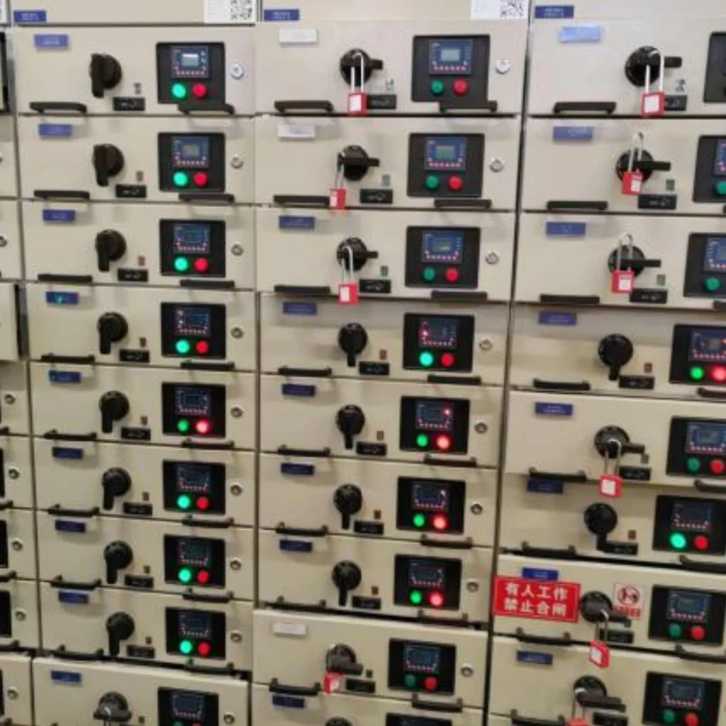
By contrast, Medium-voltage motor protection units feature larger dimensions and sophisticated functions. They are generally either flush-mounted within high-voltage switchgear cabinets, or mounted on assembled panels to facilitate centralized management and standardized layout.
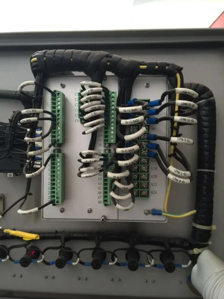
Flush mounting keeps the door wiring short.
Coordination Between Pumping Station Relay Protection and PLC Control Panels
Signal Interaction
Digital Signals (DI/DO)
Status signals such as “protection operation”, “trip command” and “equipment fault” are directly wired to the I/O modules of the PLC via hard wiring.
Analog Signals (AI/AO)
Real-time operating data of the motor including three-phase current, voltage, power and frequency can be transmitted to the PLC through 4–20 mA analog output channels for PLC monitoring and logical judgment.
Data Communication
In practical engineering, communication management units are generally installed on the unit PLC control panels and serve as transfer hubs for on-site data.
Medium voltage protection relays are connected to the above-mentioned equipment via data communication cables.
After collecting and processing various scattered protection data, the communication management unit uniformly uploads all data to the upper computer in the central control room through the station control layer network, thereby constructing a complete data transmission channel from field equipment to the monitoring center to realize the automation of the pump station system.
The PLC logs. The relay trips.
FAQ
Q1: What is the most important protection function for a water pump?
Dry-run protection is the one that pays for itself. When a pump loses suction, motor current drops to roughly 30 to 60 percent of full load, so a thermal overload element will never see it. The mechanical seal runs dry within minutes, and the pump comes back with a scored shaft and a burnt seal rather than an electrical fault.
Q2: Can a pump multifunction protection relay replace a thermal overload relay?
Yes. Most modern units include thermal overload protection plus a much wider function list.
Q3: How do I know if my pump needs underload protection?
Ask one question: can the pump ever run with nothing to move? Suction lift installations, boreholes with a falling water table, and any station where the inlet strainer can block are all candidates. If the answer is yes, enable the 37 undercurrent element and set it below the lowest current the pump draws at genuine duty.
Q4: Can one relay protect multiple pumps?
One relay per motor. Sharing a unit means one trip takes out every pump on it, and you lose the per-pump current record that turns a trip into a diagnosis. Multi-pump stations use one relay per motor and let the PLC do the sequencing.
Q5: What communication protocol should I choose?
Modbus RTU is the common and economical choice on a pump station, while IEC 60870-5-104 is what the SCADA master usually asks for on remote sites. IEC 61850 comes up on utility substation projects rather than on pump stations.
Q6: How often should relay settings be reviewed?
Once a year, and again after any change to the pump, the impeller trim, the duty point or the starting method. A new impeller moves the full load current, and a relay left on the old setting will either nuisance trip or stop protecting. Re-check the 49 curve after any process change.
Q7: How does a motor protection thermistor relay work?
The thermistor relay connects PTC thermistors embedded inside motor windings. When the motor overheats, the resistance of thermistors rises sharply. The relay detects this resistance change and sends trip signals to cut off the motor power supply, preventing winding burnout caused by over-temperature.
Q8: How does a relay protect small motors?
Relays monitor current, temperature and other operating parameters of small motors. When overload, phase loss, overheating or short-circuit faults occur, the relay will output a trip signal to disconnect the motor power supply, avoiding winding damage.
Q9: How to test a motor protection relay?
To conduct motor protection relay testing, technicians simulate a full range of fault scenarios such as overload, phase failure, current unbalance, short circuit and over-temperature. Corresponding analog and digital signals are injected to verify if the relay accurately outputs alarm and trip signals in accordance with its configuration settings.
Ask for the trip log, not the brochure.
What Sets the Price on a Pump Station Project
- Capacity sets the level. The larger the unit capacity of a pumping station, the higher the technical requirements and the cost of its relay protection.
- Key projects are specified harder than ordinary ones. Buying the cheapest unit usually fails the technical schedule.
- Voltage sets the bracket. Low-voltage motor protection devices run from about RMB 500 to 2,000, while medium-voltage units run from RMB 2,000 to tens of thousands.
Send the motor nameplate, the CT ratio, the starting method and the SCADA protocol, and the engineering team comes back with a relay schedule, a setting sheet and an I/O list you can price against. That is the shortest path from a pump list to an orderable protection panel.
Price follows the function list, not the brand.
Conclusion
A pump protection relay is bought for five faults: dry running, overload, phase loss, jamming and earth fault. Check that the relay has an element for each one before comparing prices, because a unit that covers four of them is not a cheaper version of the fifth. It is a gap in the schedule.
Three of the five are invisible to a general motor protection relay. That is the whole reason pump duty has its own product line.
Five faults. One relay.
Related Reading
Eight pages on this site carry the detail behind each function and each product range.
- Pump station automation: PLC or LCU sequencing, protection and the SCADA link around the relay.
- Motor protection relay selection: the wider selection logic behind the ANSI function list.
- Low-voltage motor protector: DIN-rail units for 380 V and 660 V pump motors.
- Which motors need differential protection: where 87M enters the schedule.
- Earth fault protection: the 51N element and how it is fed on a pump feeder.
- Setting overcurrent protection: the 50 and 51 pickup values behind the short-circuit element.
- Phase protection relays: the 46 and 47 elements on their own, with setting ranges.
- PLC control panel for pumping stations: the cabinet the relay is wired into.
Technical References
Overseas pump projects are checked against these documents.
| Source | What it covers | Type | Edition |
|---|---|---|---|
| IEC 60255-1 | General requirements for measuring relays and protection equipment | International Standard | 2022 |
| IEC 60255-149 | Functional requirements for thermal relays, the 49 function | International Standard | 2013 |
| IEC 60255-187-1 | Functional requirements for differential protection, 87M | International Standard | 2021 |
| IEEE C37.96 | Guide for AC motor protection | IEEE Guide | 2012 |
| ANSI/IEEE C37.2 | Device numbers used in protection schemes: 37, 46, 47, 48, 49, 50/51, 51N, 66 | Standard | 2022 |
| IEC 61869-2 | Current transformers: accuracy classes for protection duties | International Standard | 2012 |
| IEC 60870-5-104 | Telecontrol over TCP/IP, the SCADA link for remote stations | International Standard | 2006+AMD1:2016 |
Check the edition on the datasheet.
Note on older references. Datasheets still in circulation cite IEC 60255-1:2009 and IEEE C37.96-2006. Both have been superseded. IEC 60255-1 edition 2 and IEEE C37.96-2012 are the current documents.



About Author

Hello, I'm Leno Zhang. I have 15 years of experience in the power relay protection industry with extensive pre-sales and after-sales project experience. Our company specializes in various complete sets of relay protection and automation equipment. I can assist customers in solving all practical on-site project challenges and provide optimal integrated solutions.
Tell Us Your Requirement
High Quality
Stable performance, reliable design, ensuring safe operation for power system protection and grid stability.
Fast Delivery
Timely delivery to support your urgent orders and project schedules efficiently and professionally at any time.
Best Warranty
Professional Warranty: Reliable after-sales support for stable relay protection and long-term customer satisfaction.