

-
Leon Zhang sales consultant
-
Email: zxl635973785@gmail.com
-
Phone/WhatsApp: +86 13655813266
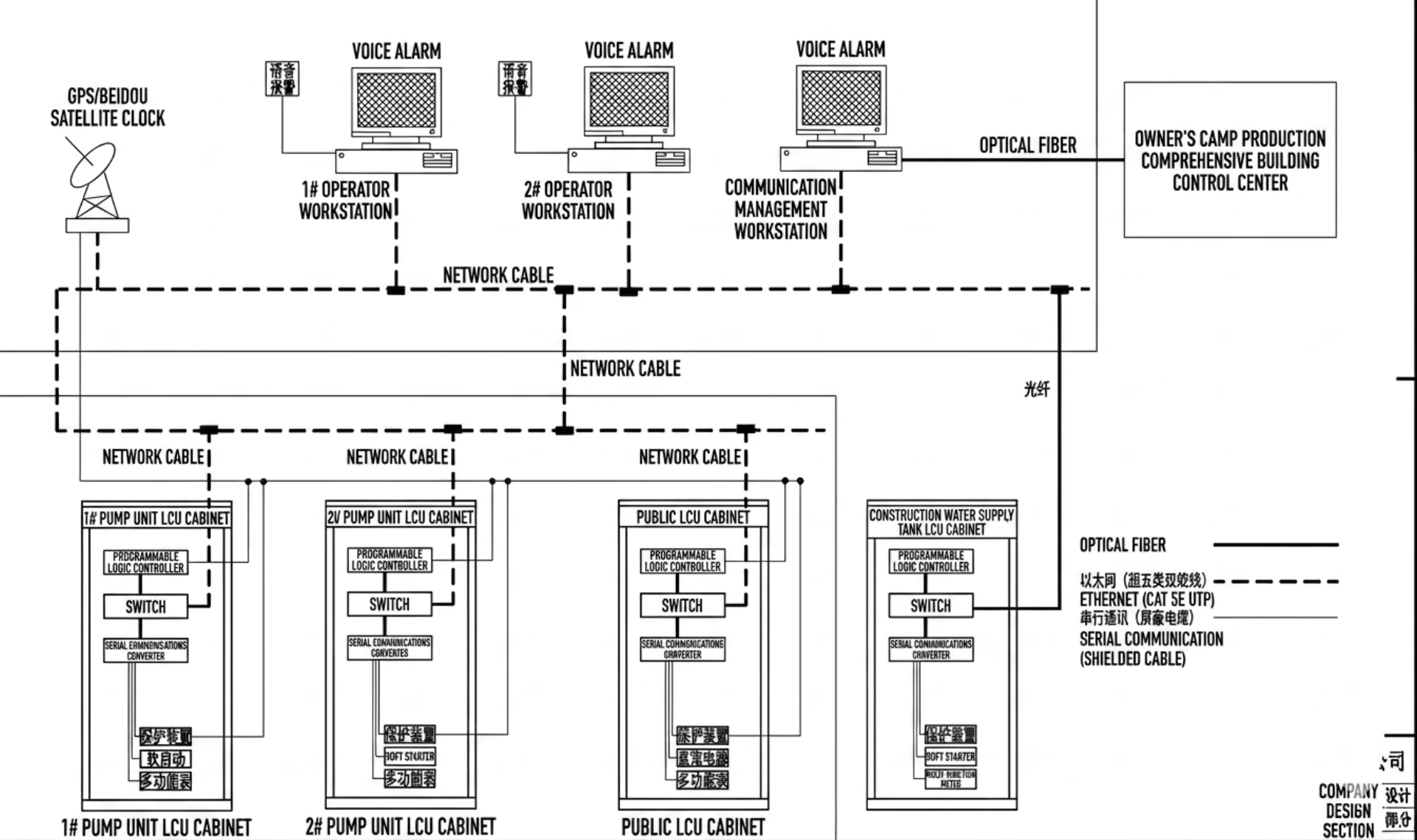
Hydropower Relay Protection & Automation Solutions
Hydropower relay protection is the set of ANSI-numbered functions that clear faults on the generator, the step-up transformer and the outgoing feeder before a fault turns into a mechanical repair. Hydro units carry a longer list than thermal machines, because they also have to survive load rejection, overspeed and motoring.
A feeder relay in a hydro station looks like a feeder relay anywhere else. What changes is the company it keeps: the turbine governor, the excitation system and the unit LCU all act on the same machine, and a trip that ignores them turns a small fault into a long outage.
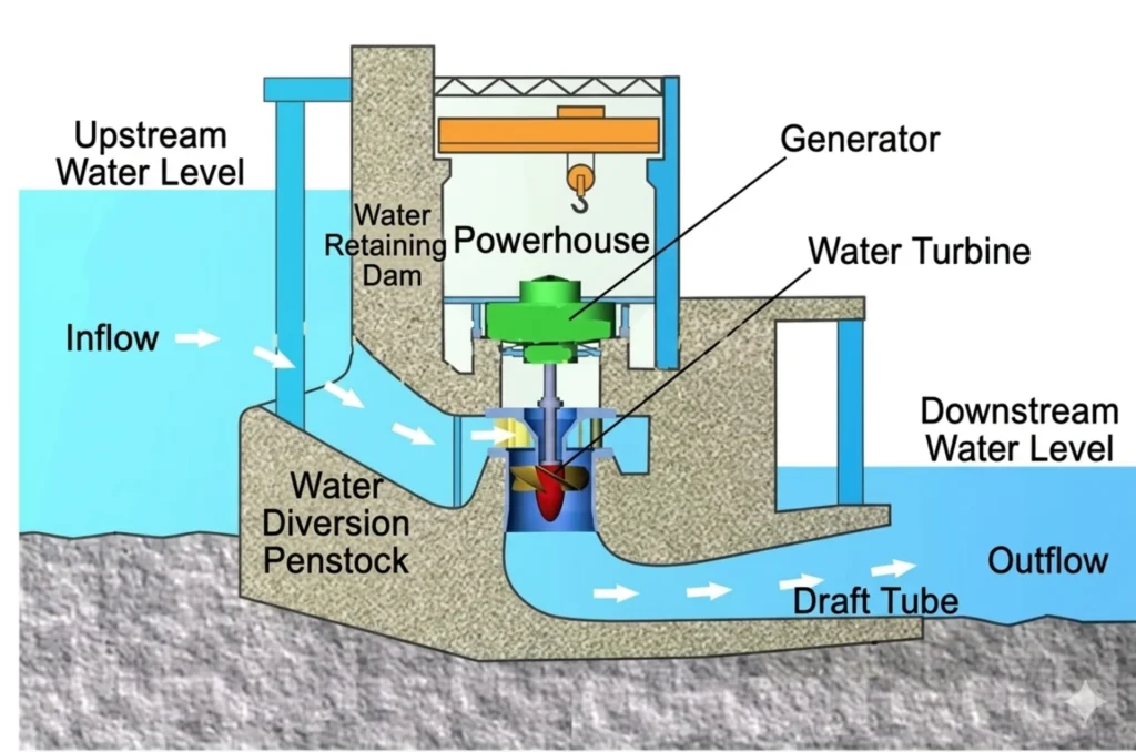
Hydropower Relay Protection at a Glance
- 87G: internal stator faults, and the only element that sees a turn-to-turn fault before it becomes an earth fault.
- 87T: step-up transformer internal faults, with inrush blocking so energising the transformer does not trip the unit.
- 40: loss of excitation, when the field collapses and the machine starts absorbing reactive power instead of supplying it.
- 32: reverse power, when the turbine stops driving and the generator motors on the grid.
- 46: negative sequence, which limits rotor heating when the load is unbalanced.
- 49 and 51V: stator overload and voltage-restrained overcurrent, both set against the generator capability curve.
- 64G and 64R: stator earth fault and rotor earth fault, the two insulation functions most often left out of an enquiry.
- 81 and 24: frequency, and volts per hertz, which decide whether the unit rides through islanding and over-excitation.
Function numbers follow ANSI/IEEE C37.2-2022. Relay performance and testing fall under IEC 60255-1:2022, and generator protection practice is set out in IEEE C37.102-2023. Station communication runs on IEC 61850-8-1 or IEC 60870-5-104, whichever the SCADA master already speaks.
Below, the protection is broken down by the equipment it guards, then the control layer that runs the unit, then what to send a supplier when you are pricing a retrofit.
What is hydropower
A hydropower station converts water energy into electrical energy by using dams and water flow.
Most stations fall into three types: run-of-river, storage behind a dam, and pumped storage. The single line diagram is similar in all three. The settings are not: a run-of-river unit sits near continuous load, a peaking unit starts and stops several times a day, and a pumped-storage set runs in both directions and motors while it pumps.
Same diagram. Different duty.
What the Protection and Automation System Has to Do
The answer lies in a well-designed protection and automation system.
Modern hydropower plants require:
- Advanced relay protection devices
- Reliable PLC control panels
- Integrated SCADA monitoring systems
- Real-time communication networks
- Intelligent fault diagnosis capabilities
This article explains how to select the right hydropower relay protection and automation equipment for hydropower plants and addresses the most common concerns raised by international EPC contractors, utilities, consultants, and plant operators.
Why Hydropower Relay Protection Sits on the Critical Path
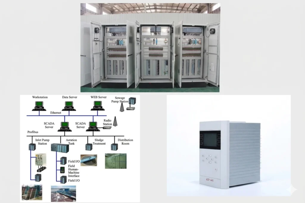
Hydropower stations contain expensive and mission-critical equipment such as:
- Generators
- Step-up transformers
- Auxiliary transformers
- Circuit breakers
- Busbars
- Transmission feeders
- Excitation systems
- Turbine control systems
Any electrical fault can result in:
- Generator damage
- Transformer failures
- Extended outages
- Production losses
- Safety risks
Hydropower relay protection systems continuously monitor electrical parameters and isolate faults before severe damage occurs.
Without proper protection, a minor fault can quickly escalate into a major plant shutdown.
Common Protection Challenges Faced by Overseas Hydropower Projects
Many international customers encounter the following problems:
Challenge 1: Which Hydropower Relay Protection Functions You Need
Questions often include:
- Which protection functions are required?
- Should numerical relays or conventional relays be used?
- How many protection layers are needed?
Challenge 2: Integration of Multiple Vendors
Many projects combine equipment from different manufacturers:
- Generators from Europe
- Switchgear from China
- PLC systems from Siemens
- SCADA software from third parties
Making four vendors talk to each other is where the schedule goes.
Challenge 3: Harsh Environmental Conditions
Hydropower plants are frequently located in:
- High-humidity environments
- Mountainous regions
- Tropical climates
- Remote locations
Protection equipment must operate reliably under these conditions.
Challenge 4: Lack of Remote Monitoring
Many older plants still depend on local operators.
Modern facilities require:
- Remote diagnostics
- Remote control
- Predictive maintenance
- Real-time fault analysis
Relay Protection Devices for Hydropower Plants
Hydropower relay protection is bought as four groups: generator, step-up transformer, outgoing feeder and busbar. Each group needs its own CT and VT inputs, and the four are rarely in one enclosure.
Four groups, four sets of CTs.
Generator Protection Relays
Generator protection is the most important protection function in a hydropower station.
Typical functions include:
| ANSI Code | Protection Device | Function Description |
|---|---|---|
| 87G | Differential Protection | Protects against internal stator winding faults |
| 50/51 | Overcurrent Protection | Detects excessive current conditions |
| 64G | Earth Fault Protection | Detects insulation failures and grounding faults |
| 59 | Overvoltage Protection | Protects generators from excessive voltage |
| 27 | Undervoltage Protection | Protects equipment during abnormal operating conditions |
| 81 | Frequency Protection | Protects against frequency deviations caused by grid disturbances |
| 32 | Reverse Power Protection | Prevents generator motoring conditions |
| 40 | Loss of Excitation Protection | Detects field collapse and the reactive power reversal that follows it |
| 46 | Negative Sequence Protection | Limits rotor heating under unbalanced load |
| 64R | Rotor Earth Fault Protection | Catches a first earth fault on the field winding before a second one shorts the rotor |
| 24 | Volts per Hertz Protection | Limits core over-fluxing during over-excitation and run-up |
Transformer Protection Relays
Hydropower transformers require:
| ANSI Code | Protection Device |
|---|---|
| 87T | Differential protection |
| 64REF | Restricted earth fault protection |
| 50/51 | Overcurrent protection |
| 49 | Thermal overload protection |
| 63 | Buchholz relay protection |
These functions prevent catastrophic transformer failures and reduce maintenance costs.
Feeder Protection Relays
Outgoing transmission lines require:
- Overcurrent protection
- Earth Fault relay protection
- Directional protection relay
- Distance protection relay 21
Proper feeder protection improves system stability and fault isolation.
Busbar Protection Systems
Busbars represent critical connection points within the power station.
Busbar protection systems provide:
- Fast fault detection
- Selective tripping
- Enhanced personnel safety
Modern numerical busbar protection can isolate faults within milliseconds.
How to Select the Right Protection Relay
A hydropower protection relay is specified on the machine, not off the catalogue. The generator capability curve, the CT and VT inventory already in the plant, and the excitation ceiling decide which elements you actually need and which you are paying for twice.
Start from the capability curve, not the datasheet.
When selecting protection relays, consider the following factors:
Plant Capacity
Protection requirements differ between:
- Small hydro plants (<10 MW)
- Medium hydro plants (10–100 MW)
- Large utility-scale stations (>100 MW)
Communication Protocols
Modern relays should support:
- IEC 61850
- Modbus RTU
- Modbus TCP/IP
- IEC 60870-5-103
- DNP3
Communication compatibility reduces integration costs.
Expandability
Future expansion should be considered from the beginning.
Choose relays with:
- Modular I/O
- Firmware upgrade capability
- Additional communication ports
Reliability and Certification
Customers should verify:
- IEC standards compliance
- EMC performance
- Environmental testing certifications
- Utility project references
Hydropower PLC Industrial Control Systems
What Is a PLC Control Panel?
An electrical PLC control panel is the operational brain of the hydropower automation system: it holds the interlocks that decide when a unit may start, run and stop.
It reads the field signals, runs the sequence logic and drives the outputs for the governor, the excitation system and the inlet valve. The protection relays trip on their own; the PLC never decides a trip.
Main Components of PLC Control Systems and Control Panel
PLC CPU
Processes control logic and automation commands.
Digital Input Modules
Receive signals from:
- Limit switches
- Breakers
- Protection relays
- Alarm contacts
Digital Output Modules
Control:
- Circuit breakers
- Motor starters
- Solenoid valves
Analog Input Modules
Collect data from:
- Temperature sensors
- Pressure transmitters
- Flow meters
- Water level sensors
Communication Modules
Provide connectivity through:
- Ethernet
- Fiber optic networks
- IEC 61850
- Modbus TCP
HMI Touch Screen
Allows local operation and status monitoring.
Power Supply System
Provides reliable power to all automation equipment.
What Do PLC Controls Handle?
PLC systems typically control:
| Category | Control Item | Core Function Description |
|---|---|---|
| Turbine Control | Turbine Governor Systems | 1. Speed regulation. 2. Load control. 3. Water flow management. |
| Auxiliary System Automation | Auxiliary Equipment | Full automation of: 1. Cooling systems. 2. Lubrication systems. 3. Drainage pumps. 4. Ventilation systems. |
| Unit Sequence Control | Generator Start/Stop Sequences | Execute automatic startup and shutdown procedures to reduce operator workload |
| Operation Monitoring | Alarm and Event Recording | Automatically log all important operational events for subsequent fault analysis and operation review |
PLC Control Unit Panel List (Examples)
| No. | Equipment Name | Model & Specification | Unit | Quantity |
|---|---|---|---|---|
| – | Unit LCU Cabinet | VIP-9000JZP | Set | 4 |
| 1 | Multi-function Digital Display Meter | VIP-E24/C900DL AC400V 5A with RS485 Communication | Set | 1 |
| 2 | Digital Voltmeter | VIP-F/C900DL AC0-400V with RS485 Communication | Set | 1 |
| 3 | Digital Frequency Meter | VIP-V/C900DL AC0-400V with RS485 Communication | Set | 1 |
| 4 | DC Ammeter | VIP-I/C900DL Input DC0-75mV with RS485 Communication | Set | 1 |
| 5 | Communication Management Unit | VIP-961A (8 Serial Ports, 4 Ethernet Ports) | Set | 1 |
| 6 | Microcomputer Automatic Synchronizing Device | DZZB-502 | Set | 1 |
| 7 | Synchronism Check Relay | DT-1/200 Front Panel Wiring | Set | 1 |
| 8 | Manual Synchronism Meter | MZ10 | Piece | 1 |
| 9 | Intermediate Relay with Base | MY2N-GS DC24V | Set | 48 |
| 10 | Changeover Switch | LW12-16/5858.3 | Piece | 1 |
| 11 | Changeover Switch | LW12-16/4.1366.4 | Piece | 1 |
| 12 | Bi-color Indicator Light (Red/Green) | AD56-22SS/RG23 | Piece | 1 |
| 13 | Push Button Switch | LAY50-22DS-20/K | Piece | 1 |
| 14 | Push Button Switch | LAY50-22D-40Z/R with Protective Cover | Piece | 1 |
| 15 | Flashing Buzzer (Yellow) | AD56-22SM/Y23 DC24V | Piece | 1 |
| 16 | Rotary Switch | LAY50-22DX-20CXS/K | Piece | 3 |
| 17 | Rotary Switch | LAY50-22DX-20CXS/Kffu | Piece | 2 |
| 18 | Push Button Switch | LAY50-22DX-22/W23 | Piece | 1 |
| 19 | Isolation Transformer | BK70VA, 220V/220V | Piece | 1 |
| 20 | PS24V Power Supply | NDR-240-24V AC/DC 10A | Piece | 2 |
| 21 | PLC Processor Module ST60 | 6ES7 288-1ST60-0AA1 | Set | 1 |
| 22 | DI/DO Expansion Module | 6ES7 288-2DT32-0AA1 | Piece | 6 |
| 23 | 155 Interface Module | 6ES7 155-6AA01-0BN0 | Piece | 1 |
| 24 | 16DI Module | 6ES7131-6BH01-0BA0 | Piece | 4 |
| 25 | Analog Input Module 8AI 4~20mA | 6ES7 134-6GF00-0AA1 | Piece | 4 |
| 26 | Active Base Module | 6ES7 193-6BP00-0DA0 | Piece | 2 |
| 27 | Standard Base Module | 6ES7 193-6BP00-0BA0 | Piece | 6 |
| 28 | Touch Screen with Software Programming | TPC1570Gn, 15.6″ | Piece | 1 |
| 29 | Ethernet Switch | IES215 Unmanaged 5 Electrical Ports | Set | 1 |
| 30 | Power Socket | AC30-10530 10A/250V 5-Hole | Piece | 1 |
| 31 | Power Surge Protector | KDM/MD220-20 | Piece | 1 |
| 32 | Miniature Circuit Breaker (MCB) | HG45Z-63 2P C3 | Piece | 10 |
| 33 | Miniature Circuit Breaker (MCB) | HG45-63 2P C3 | Piece | 3 |
| 34 | Miniature Circuit Breaker (MCB) | HG45-63 3P C1 | Piece | 2 |
| 35 | Cabinet Interior Lighting | AC220V | Set | 1 |
| 36 | Control Cabinet and Accessories | 2260800600mm | Set | 1 |
For small hydropower stations, low cost PLC controllers are recommended. They have relatively low technical requirements and limited budgets, so entry-level models such as basic Siemens PLCs are more than sufficient for on-site operation.
Complete Production Process of Hydropower PLC Control Cabinet
1. Equipment Model Selection
According to project parameters, I/O point requirements, on-site operating conditions and types of PLC controls, PLC modules, electrical components, cabinet wires and other auxiliary materials are selected in compliance with hydropower industry standards to ensure equipment compatibility, anti-interference performance and operational stability.
2. Scheme Design
The PLC control panel design follows hydropower control and interlock protection requirements to finalize cabinet layout, circuits and strong/weak current isolation. It is equipped with dustproof, moistureproof and anti-interference measures, with optimized control logic, alarm and data transmission.
3. Drawing Design
Accurate electrical schematic diagrams, layout drawings, terminal diagrams and PLC control wiring diagrams with complete parameter and point marking are compiled and verified, providing official technical guidelines for production, commissioning and subsequent operation and maintenance.
4. Cabinet Panel Assembly
Cabinet processing, component installation and wiring are carried out strictly in accordance with finalized drawings. Strong and weak current circuits are separated completely with standardized wiring and clear marking to avoid connection errors and ensure qualified assembly quality.
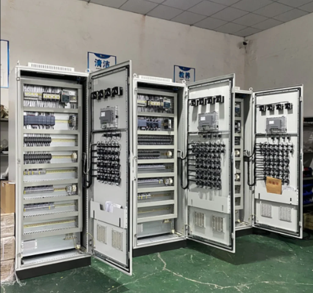
5. Complete Machine Testing
A full set of factory tests including insulation test, power-on test, function debugging, communication test and fault simulation are conducted to verify the control and protection performance. All defects are rectified and retested to ensure zero hidden quality risks.
6. Packaging and Delivery
Complete technical documents are sorted out. The equipment is cleaned and protected with waterproof and shockproof packaging. After information verification, products are delivered to ensure intact arrival at the project site.
Where the Unit LCU Meets the Protection
Hydro LCU protection is not a separate relay. The unit LCU cabinet carries the start and stop sequence, the annunciation and the interfaces to the governor, the excitation system and the inlet valve. The trip decision stays in the protection relay, on its own CT and VT inputs and its own DC supply.
A hydropower relay protection panel and the unit LCU often sit in the same lineup and are frequently bought on the same order. They are still two different documents: the relay schedule comes from the machine data and the short-circuit study, the LCU specification comes from the operating sequence the owner wants.
Three interfaces are worth writing down before either cabinet goes into production:
- Trip outputs: the relay drives the breaker coil directly. A trip routed through the PLC adds a scan time nobody has budgeted for.
- Interlocks: the LCU blocks a start while a protection alarm is standing. It does not clear the alarm.
- Signals upward: the relay sends events and disturbance records on IEC 61850 or IEC 60870-5-104, the LCU sends plant status, and both land in the same historian.
The relay trips. The LCU sequences.
Get the interface list wrong and the commissioning team finds it on site.
SCADA Systems for Hydropower Plants
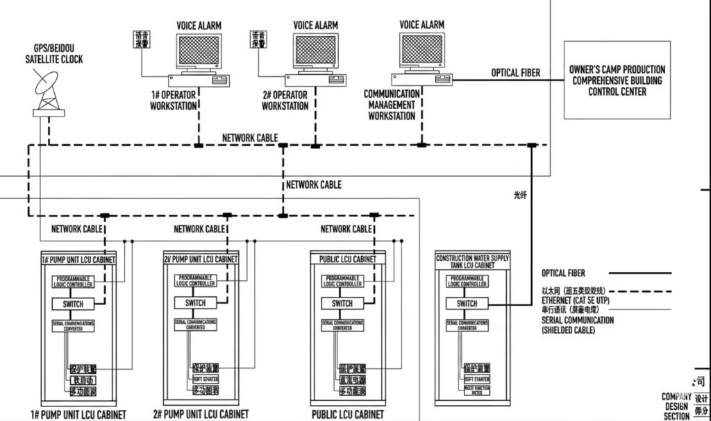
Why SCADA Is Essential
SCADA (Supervisory Control and Data Acquisition) provides centralized monitoring and control.
Operators can access plant information in real time from a control room or remote location.
Core SCADA Functions
Real-Time Monitoring
Monitor:
- Voltage
- Current
- Power output
- Water levels
- Equipment status
Remote Control
Operators can:
- Open and close breakers
- Start generators
- Stop equipment
- Modify operating parameters
Alarm Management
SCADA systems instantly notify operators of abnormal conditions.
Historical Data Storage
Data trends help identify equipment degradation before failures occur.
Report Generation
Automatic reports support:
- Regulatory compliance
- Operational analysis
- Maintenance planning
Key Requirements for Modern Hydropower SCADA Systems
International customers increasingly request:
Cybersecurity Features
Protection against:
- Unauthorized access
- Malware attacks
- Network intrusions
Redundant Architecture
Ensures operation during:
- Server failures
- Communication failures
- Power interruptions
Multi-Station Management
Utilities often monitor multiple hydropower plants from one control center.
Mobile Access
Remote access via:
- Smartphones
- Tablets
- Web browsers
Integrated Protection and Automation Solutions
Hydropower automation solutions bundle the protection panels, the unit LCU, the station SCADA and the communication gateways under one set of drawings and one factory acceptance test. On a retrofit that matters more than the hardware: the interface between the new relays and the existing governor is where schedules slip.
Instead of purchasing individual components from multiple suppliers, many hydropower developers prefer integrated solutions.
Benefits include:
- Faster project implementation
- Reduced engineering costs
- Simplified commissioning
- Easier maintenance
- Single-source technical support
A complete solution typically includes:
- Generator protection panels
- Transformer protection panels
- Feeder protection panels
- PLC control cabinets
- SCADA software
- Communication gateways
- Engineering services
- FAT and SAT support
Case Study: Hydropower Plant Modernization Project
A hydropower station required upgrading its aging protection and automation infrastructure.
Challenges included:
- Frequent relay malfunctions
- Lack of remote monitoring
- Limited spare parts availability
The solution included:
- Numerical relay protection systems
- PLC-based automation panels
- Integrated SCADA platform
- IEC 61850 communication network
Results:
- Improved system reliability
- Faster fault diagnosis
- Reduced maintenance costs
- Enhanced operational efficiency
Frequently Asked Questions (FAQ)
What protection relays are required for a hydropower generator?
Typical functions include differential protection, overcurrent protection, earth fault protection, frequency protection and reverse power protection. On a hydro unit add 40 for loss of excitation, 46 for negative sequence and 64R for rotor earth fault. Which of them are mandatory depends on the machine rating: below roughly 10 MW most owners accept a reduced set, above it the utility usually specifies the full list.
Can PLC systems communicate with protection relays?
Yes. Modern PLCs speak IEC 61850, Modbus TCP and IEC 60870-5-104, so relay events, measurements and disturbance records reach the SCADA and the HMI without a protocol converter in between.
Is SCADA necessary for small hydropower plants?
Yes, but the scope should match the plant. A small run-of-river station needs alarm annunciation, a trend log and remote visibility of the unit status, not a redundant server pair. The cost that matters is the communication gateway and the engineering time, and both scale with the number of devices rather than with the rating of the plant.
What is a programmable logic controller (PLC)?
It is an industrial computer built for control duty: it reads input signals, runs a control program in a fixed scan cycle and drives outputs. In a hydropower station it runs the unit start and stop sequence, the auxiliary systems and the interlocks, and it reports plant status upward to SCADA.
How does a PLC controller work?
A PLC operates in a cyclic scanning mode, mainly including three stages: input sampling, program execution and output refresh. It collects field signal status, runs control logic and drives on-site actuators continuously to realize automatic control. Scan times on hydro unit sequences run in tens of milliseconds, fast enough for interlocks and far too slow for tripping.
Can existing hydropower stations be upgraded without major shutdowns?
In most cases, modernization can be implemented in phases to minimize operational interruptions. The usual order is one unit at a time: new protection panel and LCU first, then the communication gateway, then the SCADA master, with the old panel left live until the new one has passed its site acceptance tests.
How long does a complete hydropower protection and automation project take?
Depending on project size, engineering, manufacturing, testing and commissioning typically require several months. A single-unit retrofit on standard panels runs about four to six months from order to site acceptance. A multi-unit station with a new SCADA master and a new communication network takes longer, and most of that time goes into data collection, not manufacturing.
Does the unit LCU replace the protection relay?
No. The LCU runs the sequence and the interlocks; the protection relay decides the trip. They share the same cabinet lineup and often the same order, but the relay keeps its own CT and VT inputs, its own DC supply and its own trip outputs to the breaker coil. Putting the trip through the PLC adds a scan time that no protection study accounts for.
Conclusion
Reliable relay protection and automation systems are the foundation of modern hydropower plant operation. Properly selected protection relays, PLC control panels, and SCADA systems improve safety, reduce downtime, and maximize energy production.
For EPC contractors, utilities and plant owners, the saving is in the interfaces: one supplier for the protection panels, the LCU and the SCADA means one set of drawings and one factory acceptance test to argue over.
New station or retrofit, the order of work is the same: fix the single line, fix the CT and VT inventory, then choose the relays. Send the machine data, the CT ratios and the SCADA protocol, and the engineering team comes back with a relay schedule, a setting sheet and an I/O list you can price against.
Related Reading
- Generator protection relay: the ANSI function list for the machine itself, element by element.
- Hydropower plant upgrade solution, Vietnam: a retrofit carried out unit by unit without a station shutdown.
- ATN-400 SCADA system: the station-level layer above the unit LCU.
- PLC control panel for hydropower and pumping stations: the controlgear side of the same scope.
- Generator and transformer protection cabinets: panel-level scope when the two are bought together.
- Low-voltage generator protection relay: for small units where a full ANSI list is not justified.
- Excitation panel: the other cabinet the protection has to agree with.
- Generator protection relay panel, ANSI 11: a packaged panel for single-unit stations.
- Step-up transformer protection: 87T setting notes for the station transformer.
- Pump station automation and PLC control relays: the same LCU pattern on the pumping side.
Technical References
These are the documents hydropower relay protection panels are checked against on overseas projects.
Check the edition on the datasheet.
| Source | What it covers | Type | Edition |
|---|---|---|---|
| IEC 60255-1 | General requirements for measuring relays and protection equipment | IEC standard | 2022 |
| IEC 60255-187-1 | Functional requirements for differential protection, the 87G and 87T elements | IEC standard | 2021 |
| ANSI/IEEE C37.2 | Device numbers used throughout this page | IEEE standard | 2022 |
| IEEE C37.102 | Guide for AC generator protection | IEEE guide | 2023 |
| IEC 61869-2 | Current transformers: accuracy classes for protection duty | IEC standard | 2012 |
| IEC 61850-8-1 | Station communication: mapping to MMS and GOOSE | IEC standard | 2011+AMD1:2020 |
| IEC 60870-5-104 | Telecontrol over TCP/IP for the SCADA link | IEC standard | 2006+AMD1:2016 |
| IEC 61131-3 | PLC programming languages used in the unit LCU | IEC standard | 2025 |
| IEC 61439-2 | Controlgear assemblies: temperature rise, short-circuit withstand and clearances | IEC standard | 2020 |
| IEC 60529 | IP degrees of protection for cabinets in wet plant areas | IEC standard | 1989+AMD1:1999+AMD2:2013 |
Older references. Datasheets and enquiry packages still in circulation cite IEC 60255-1:2009 and IEEE C37.102-2006. Both have been superseded, and a compliance statement against either one is worth querying before it goes into a contract.



About Author

Hello, I'm Leno Zhang. I have 15 years of experience in the power relay protection industry with extensive pre-sales and after-sales project experience. Our company specializes in various complete sets of relay protection and automation equipment. I can assist customers in solving all practical on-site project challenges and provide optimal integrated solutions.
Tell Us Your Requirement
High Quality
Stable performance, reliable design, ensuring safe operation for power system protection and grid stability.
Fast Delivery
Timely delivery to support your urgent orders and project schedules efficiently and professionally at any time.
Best Warranty
Professional Warranty: Reliable after-sales support for stable relay protection and long-term customer satisfaction.